Electronics Design
1. Week assignment
Redraw the echo hello world board, adding at least a LED.
2. Development Environment
I used Eagle, GIMP, and FabModules.
3. The Hello World Board
Based on the hello world board file provided by Fab Archive Tutorials, i started modifying the circuit provided.
Note: after opening the file, you also need to import the FabLab (also found in the tutorials) eagle library.
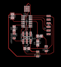
I added a LED and also a thermistor for measuring the temperature. Here’s the schematic:
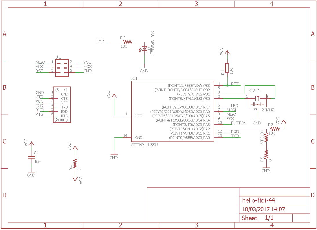
Overview of components:
- Attiny44A: the microcontroller
- 6-pin ISP connector: for programming the board
- FTDI header: powers the board and allows board to talk to computer
- XTAL1 20MHz: resonator, used as external clock; the attiny has a 8Mhz clock but the resonator is faster (increase the clock speed of the processor) and more accurate.
- C1 - 1u: capacitor between VCC and GND for stabilizing voltage ripples that could rise. The nearer is to the sources, the better it is.
- R1 - 10k: pull-up resistor on RST pin (more on here)
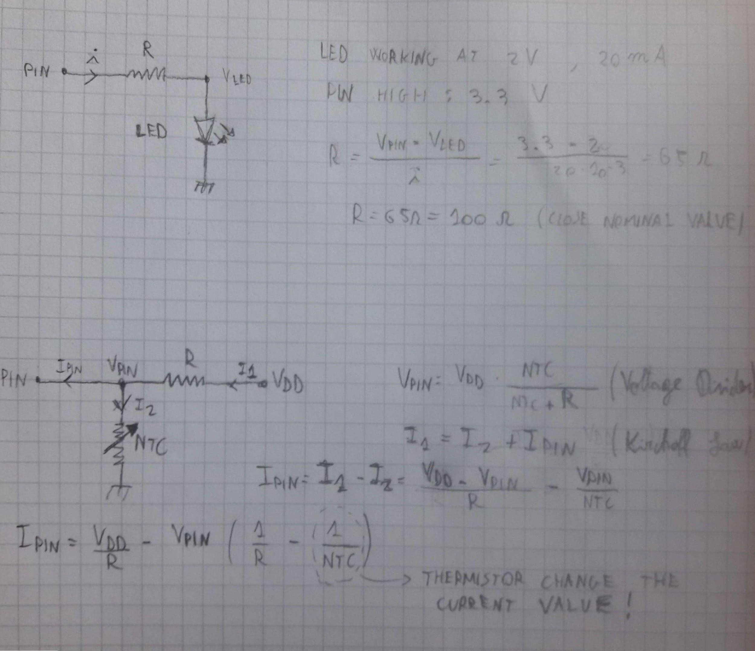
- NTC10k - 10k nominal value: thermistor. A thermistor is a resistor with varying resistance as the temperature changes. In particular NTC series resistance goes down as temperature goes up. The nominal value is the resistance value for 25°.
- R2 - 10k: with the NTC, they make up a voltage divider for lowering the current entering the input pin; as the NTC resistance has got a lot of excursion, it could burn the IC as current would goes too up.
- R3 - 100: used as current limiter for LED
- LED
R4 - R5 0: used as jumpers.
I then used board editor to make the traces.
Remember to check Eagle Design rules while making traces: I have this set up for 1/64 Roland endmill
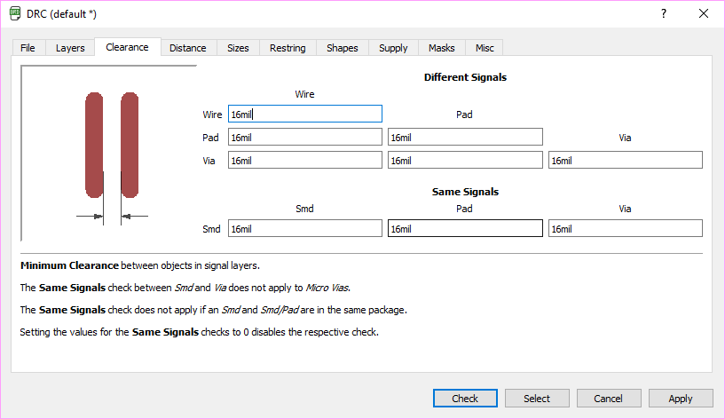
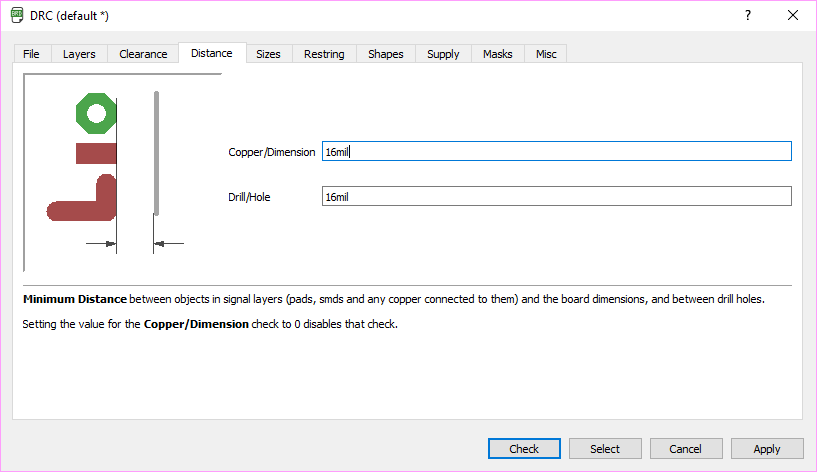
Eagle’s DRC is used to avoid problems while milling (cut traces, cut out pads) due to too near traces/components and it is so important!
Tip: trace the routes by hand, even if is more time consuming, and don’t use autorouter: as we are using single-sided material, the autorouter is not able to make routes only with a layer (except if you don’t place the component so well, but if you do that you can make routes manually)
I then moved on milling the board.
I used 1/64 inch mill for traces and 1/32 inch mill for cutting.
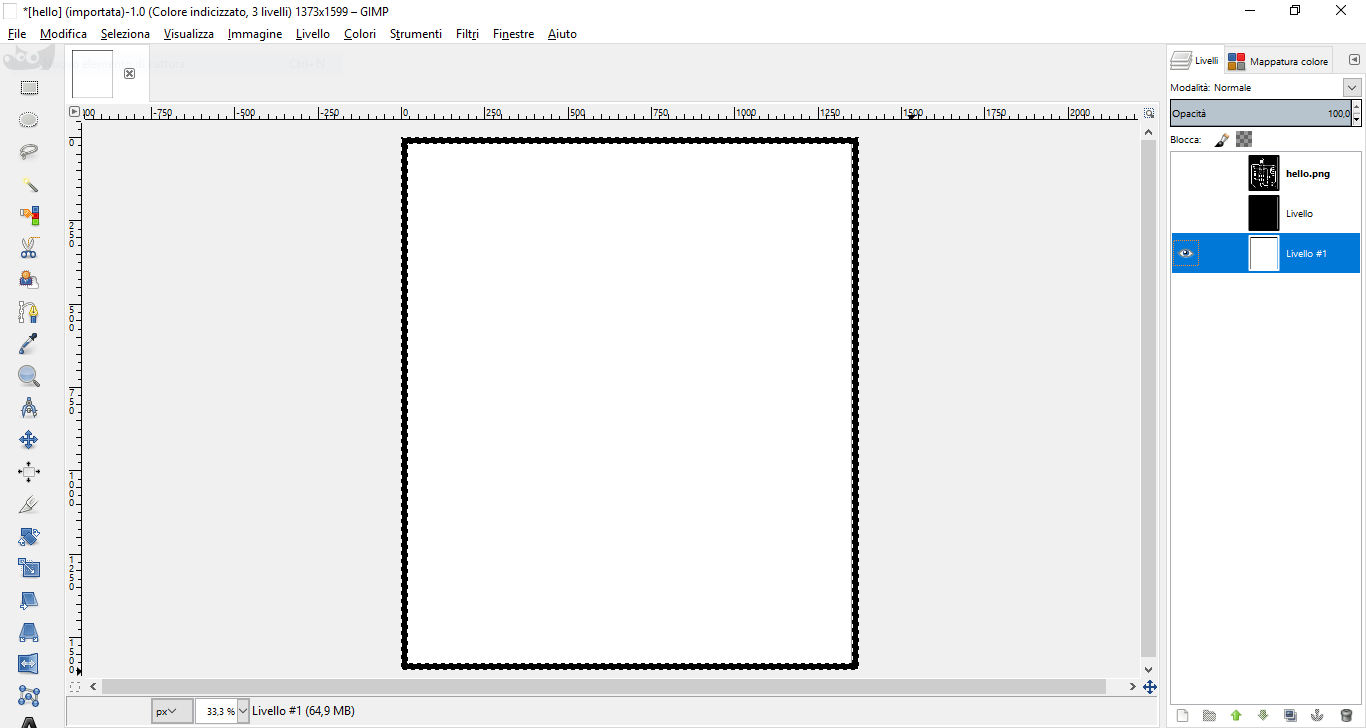
Using GIMP and FabModules (for how to use FabModules see Week 4) i made the RML file for the Roland SRM 20.
To use gimp for making the images:
- open image
- Image-> Autocrop Image
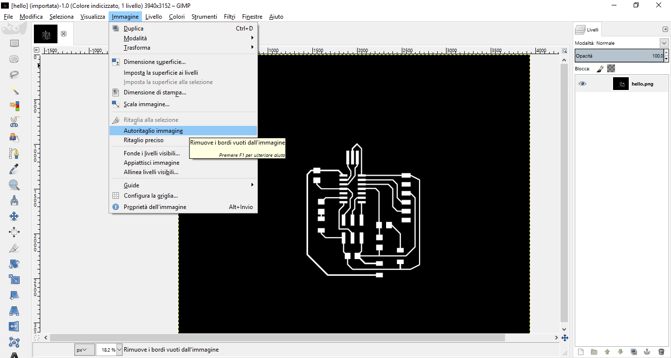
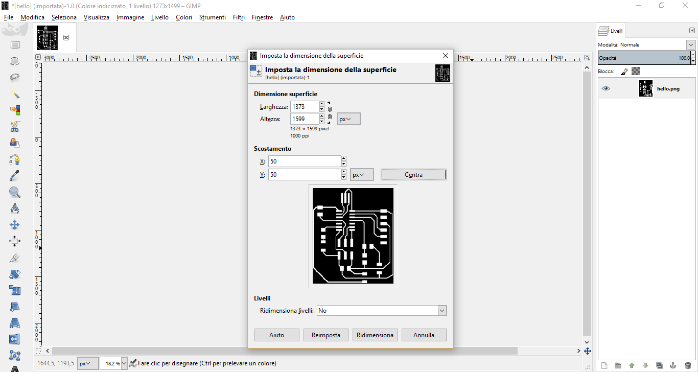
- Image-> Canvas Size
- add 100 px per each dimension and click on Center
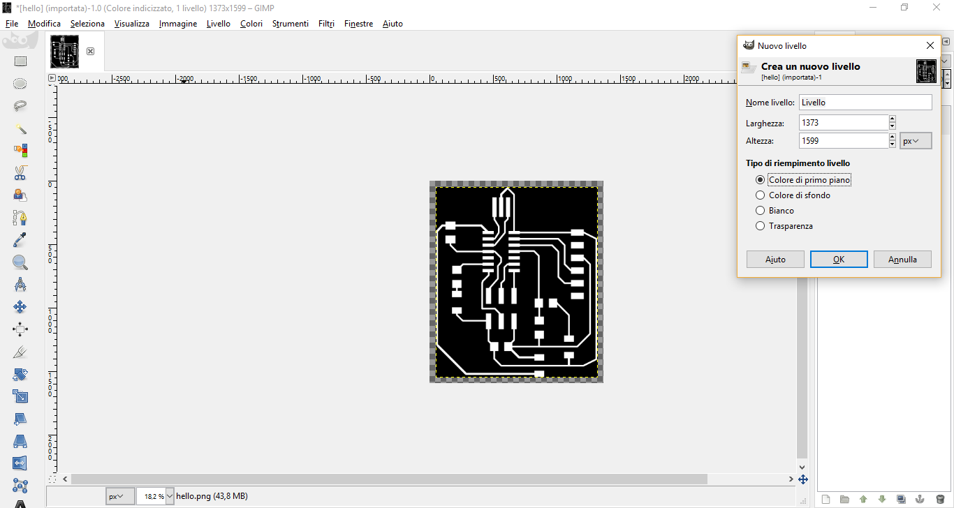
- New Layer..-> Foreground color
- drag and drop new layer under the starting one
- New Layer..-> White
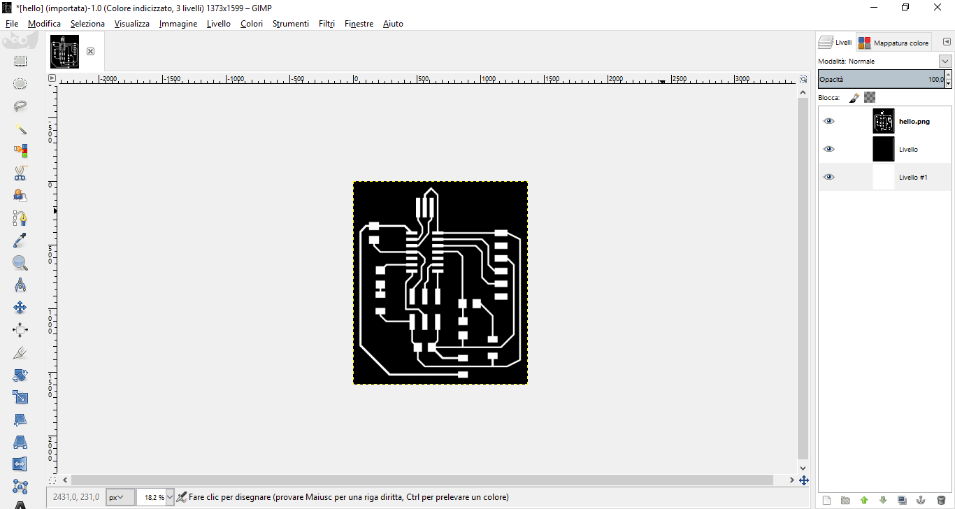
- Select-> All
- Select-> Shrink and set 20px shrink
- Select-> Invert - check if a border is flashing
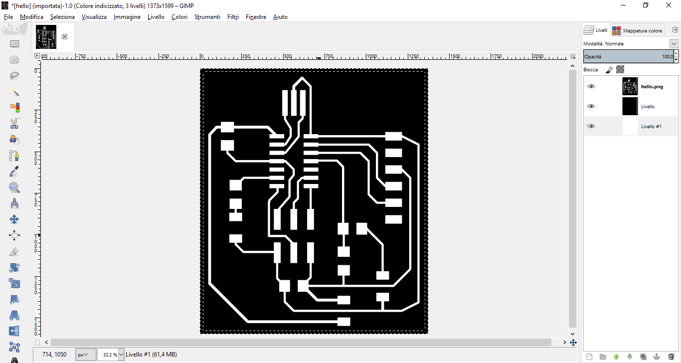
- Tools--> Paint tools-> Bucket fill and set black color
- fill in the flashing border with black
- export first traces and black layer (hide white layer): this will be traces .png file
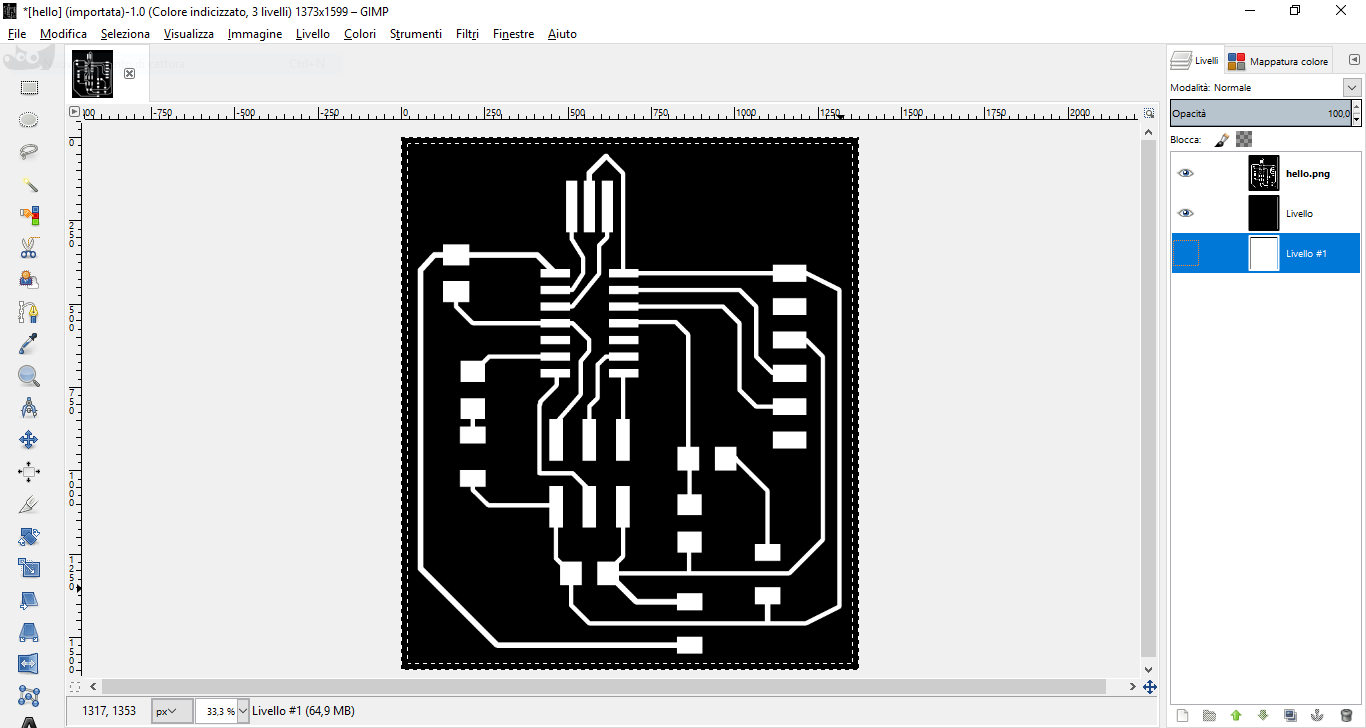
- export white and black layer (hide traces layer): this will be outline .png file
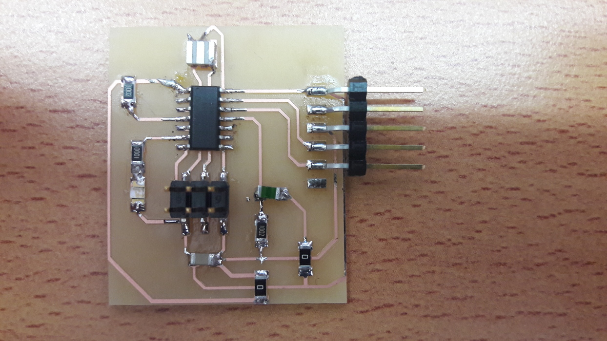
After the milling, I soldered all the components on the board.
Notes: when soldering LED, care for the cathode (it’s indicated behind the LED itself) as it must go to the ground.
Here’s the final result, with all components soldered (a little bit of solder flux got burned!)
5. Files
Board Eagle files, .png of traces and .rml for roland - .zip
Update
It's possible to find more work about this week on the final project page in the related development section