Output Device
1. Week assignment
Add an output device to a microcontroller board you've designed and program it to do something
2. Development Enviroment
I used Arduino IDE, Eagle and fabmodules for Roland SRM-20.
3. First try
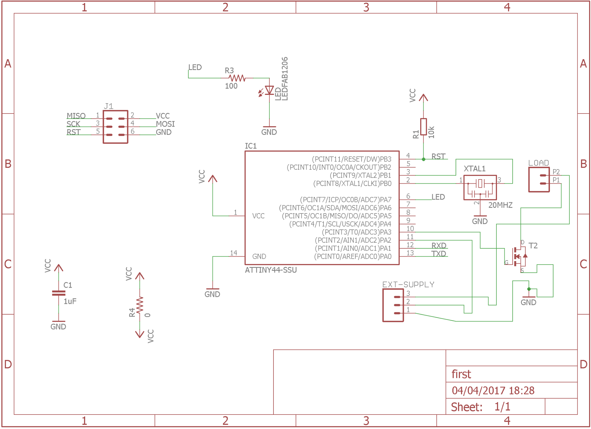
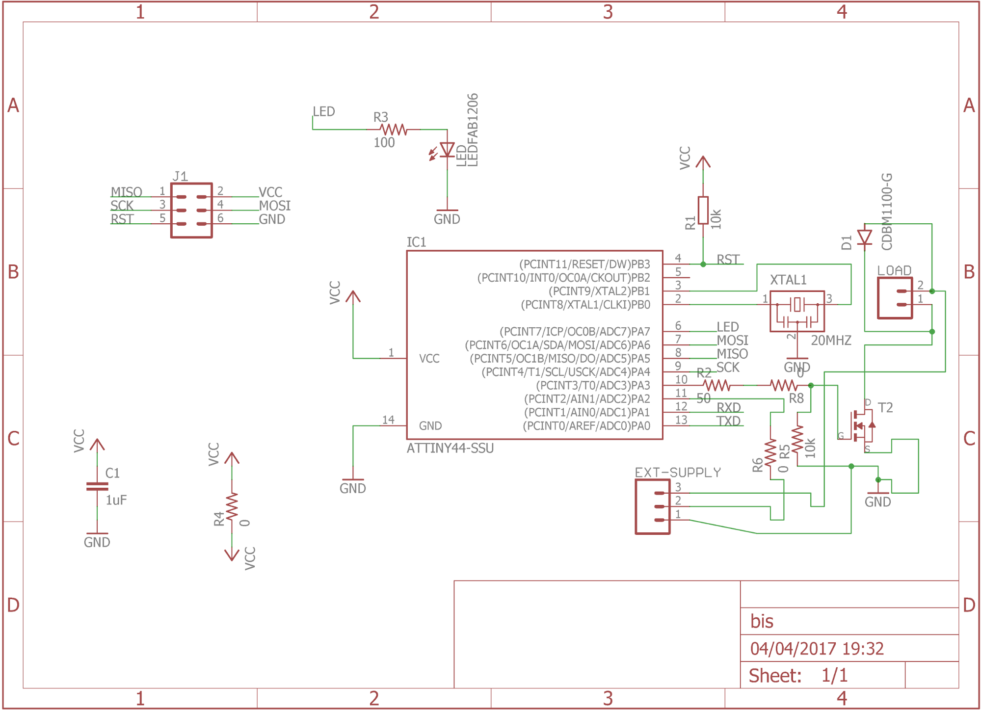
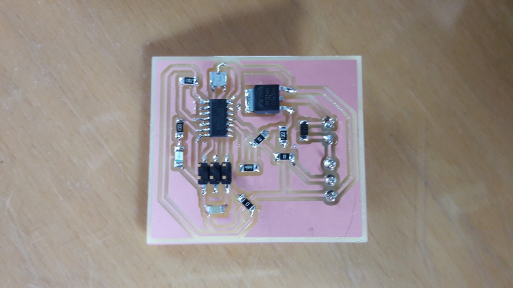
I modified my hello world board to control a MOSFET (using a n-MOSFET RFD16N05LSM)
A MOSFET (Metal Oxide Semiconductor Field Effect Transistor) is a electronic component which behaviour changes based on the electrical field in the body.
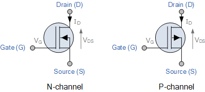 Circuital simbol
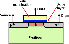 How it’s made (P-silicon is the body)
We have three connectors: gate (G), drain (D), source (S).
One of its fundamental parameter is the threshold voltage (Vth), the tension between G and S (Vgs) and the tension between D and S (Vds), which gives us three ways of working:
1 - Vgs < 0, interdiction: the MOSFET is like an open circuit, no current is flowing between D and S
2 - Vgs < Vds-Vtn, triode: a small current flows from D to S
3 - Vds > Vgs-Vtn: saturation: bigger current flows, usually we use it in this mode
So, we can use this component like a voltage driven switch: if I apply an high tension on G, the switch is closed (like a short-circuit) otherwise the switch is open (like an open circuit).
We have another type of MOSFET: the p-mosfet, where the current flows from S to D and it is interdicted if Vgs has a high value and it is in saturation if Vgs has a low value.
Some notes: no or small current flows into the gate (due to construction), and when the MOSFET is in saturation region it has a behaviour like a resistor, which value can be read from datasheet.
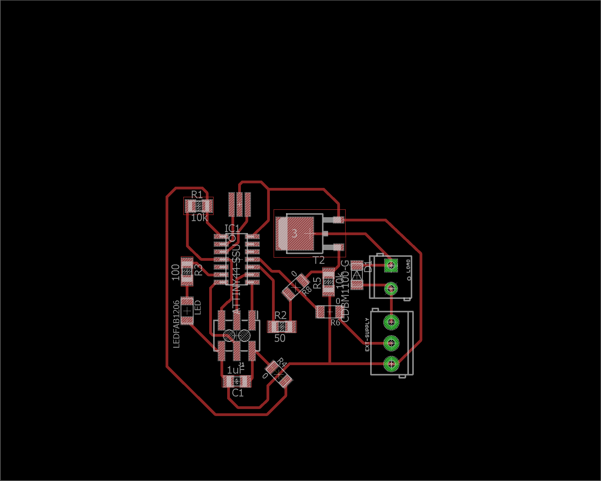
This is the circuit:
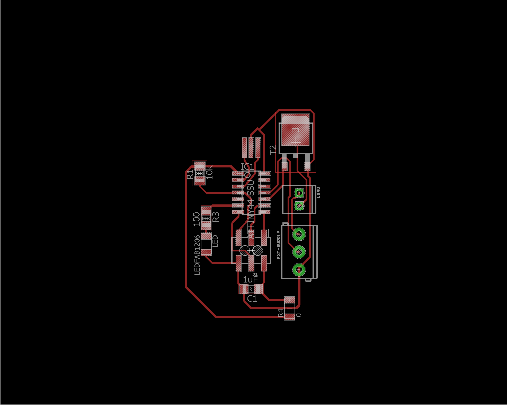
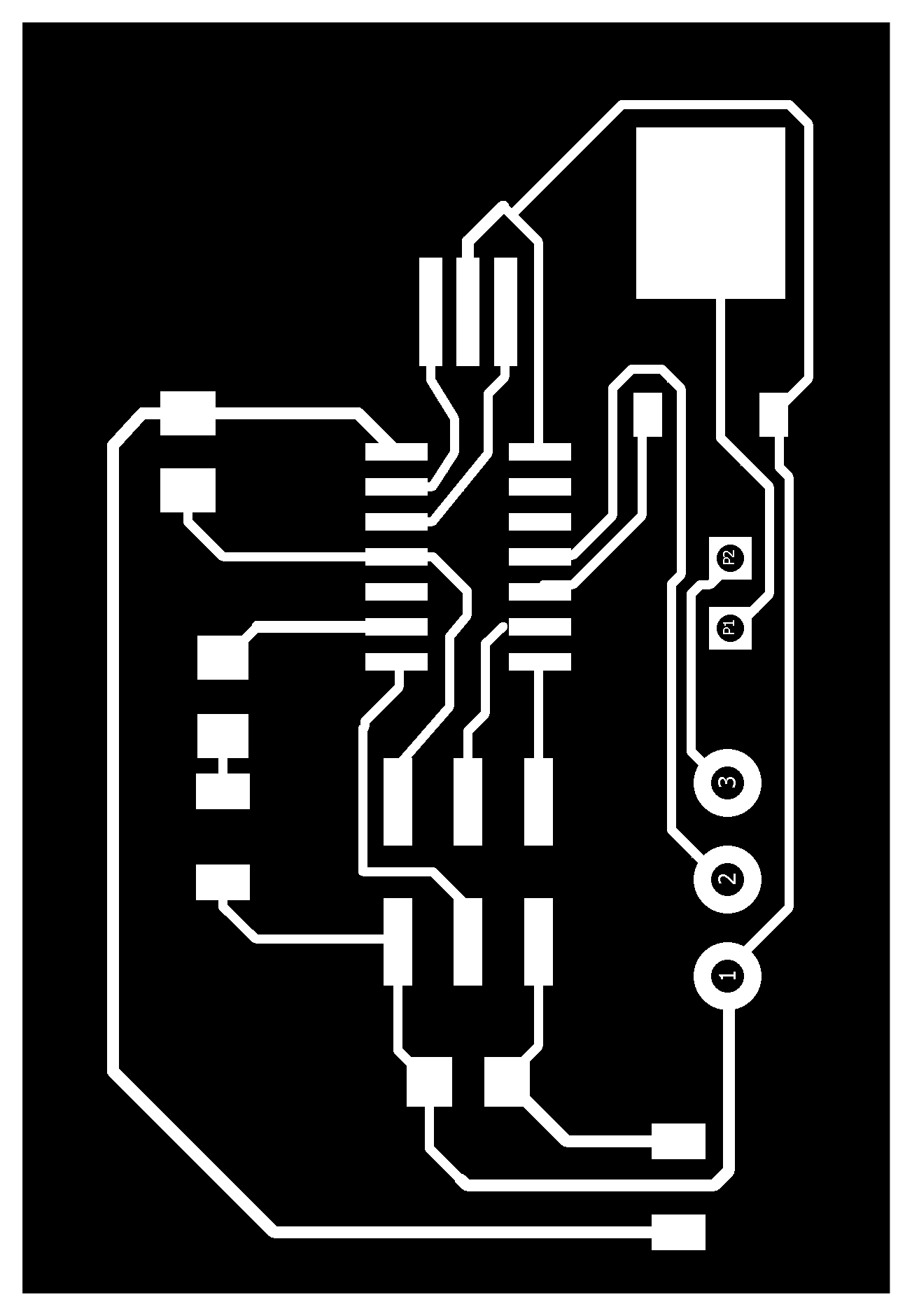
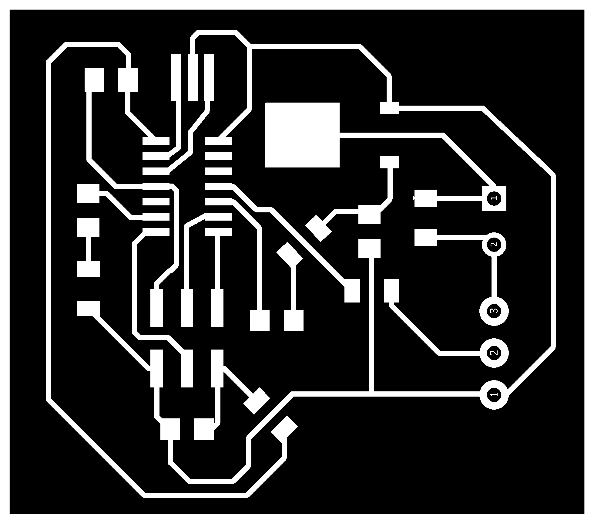
Traces
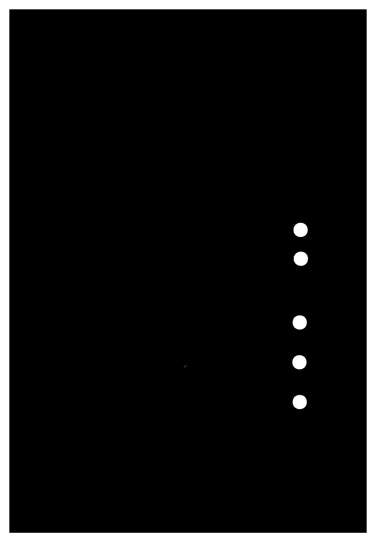
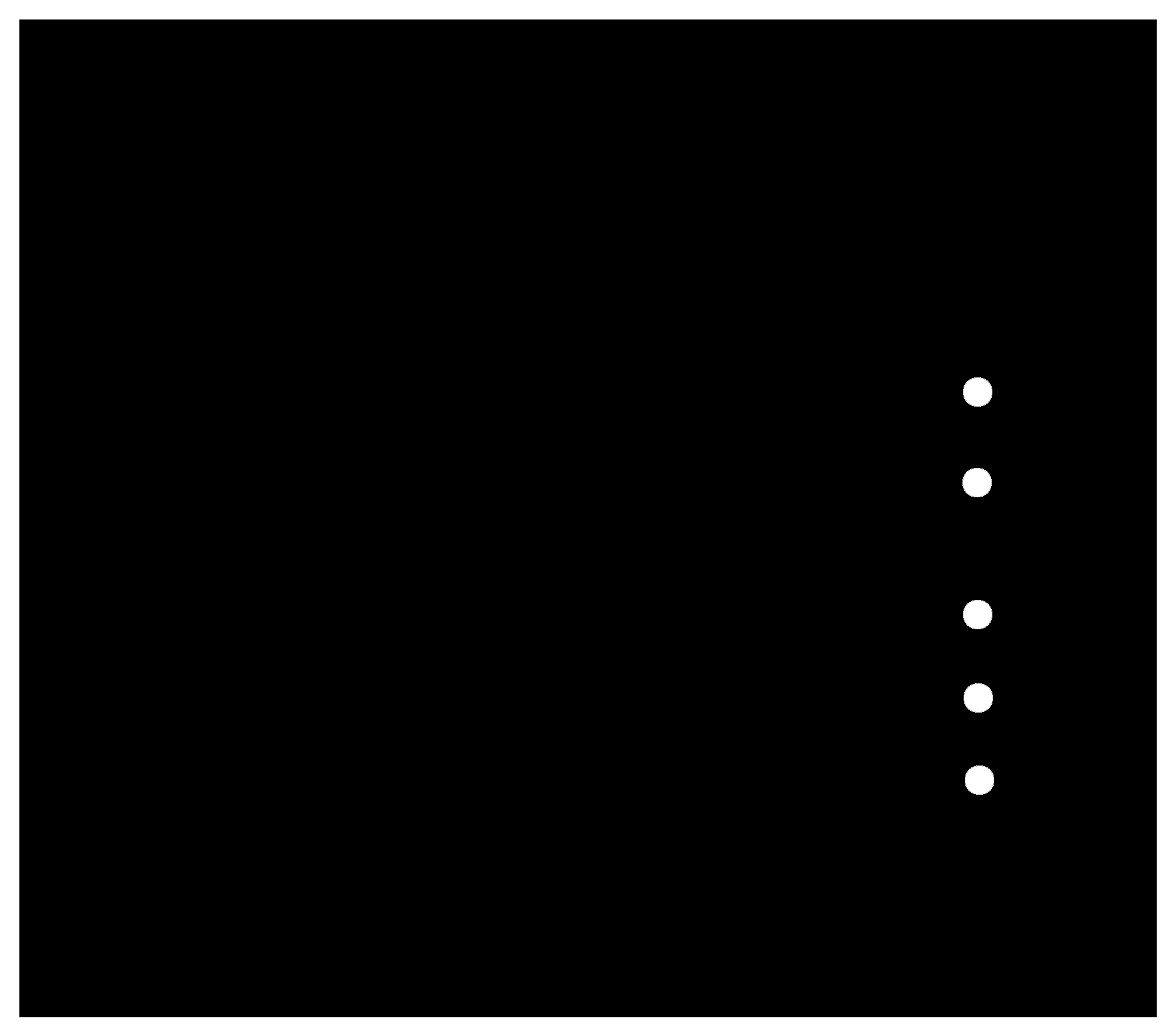
Outline
I use two connectors (screw connectors) to plug in an external voltage supply and the object i want to control.
Note: you have to add holes in the board for screw connectors: 1.2 mm is good for the one we have in lab. I made the hole with the same outline files (the outline png must be inverted from fabmodules).
I need to use a MOSFET because the tension/current needed are bigger than the one the ATTiny uses and supplies.On pin 10 I control the MOSFET, like a switch: digital high means switch closed, digital low means open.
On pin 2 i can control/read external PWM (some fans, i.e., have one line to control speed).
However, this circuit did not work!
I did several errors:
- no pull-down resistor on pin 10: this leaves the pin in a “floating” status. In this circuit, leaving the attiny shutdown should interdict the diode, but, measuring with a voltmeter, I had like 1.90 volts on that pin (which is higher than the threshold voltage Vth read in the datasheet)
- No protection for residual currents flowing in the circuit: no protection for high currents who can damage the attiny!
As said, the board had a lifespan of almost 2 hours.
I tried using it to control a 24V 0.1A fan. After some time I touched the board, and the ATTiny was so hot I burned myself.
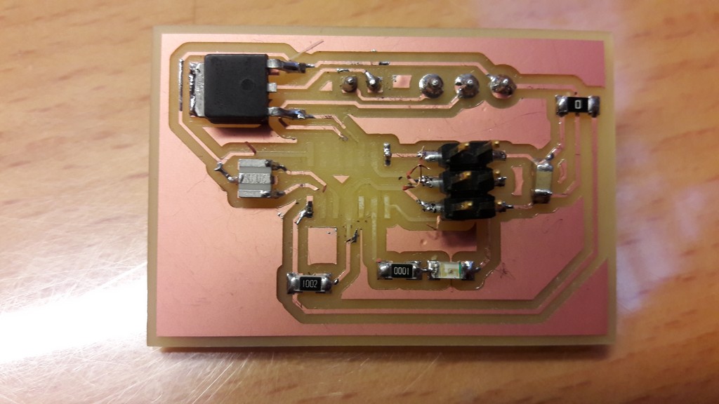
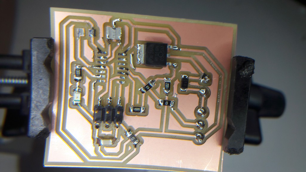
Unlucky day. Tried also to desolder the ATTiny and desoldered the tracks too, and this is the only picture of the board I have!
4. Second Try
Then, based on some suggestions, I modified the circuit: I added a voltage divider on pin 10 as pull-down resistor and a Schottky diode (a faster switching diode) with a breakdown tension of 100 volts and a max tolerable current of 1 ampére, in parallel with the load: it can handle residual currents.
Traces
Outline
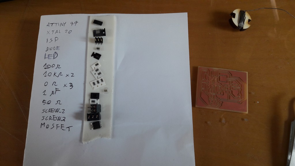
After milling the board, i began soldering:
Then, I tried programming the board, using Arduino IDE.
On burning the bootloader i had communication error.
After checking with a multimeter all the connections, on my instructor advice i desoldered the ATTiny, due to cold solders, and the 10k pull-up resistor on RST.
Then, the programming (after burning the bootloader) went fine.
I then plugged in the external supply (used for powering the fan) but, on powering it on, I had a C.C. and low output tension and current.
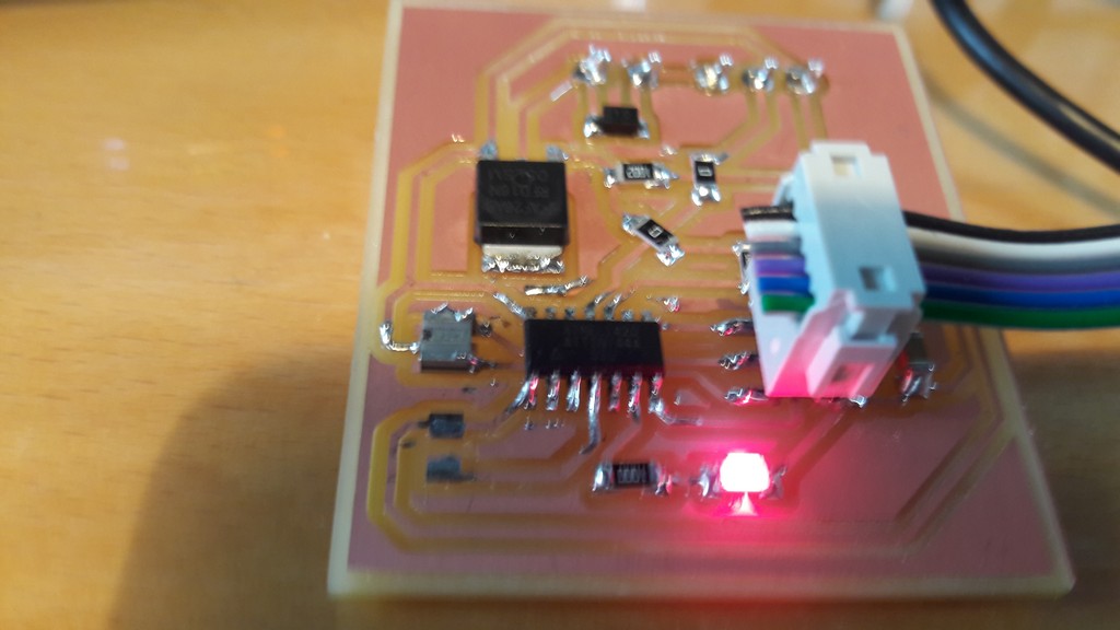
The diode cathode was on the wrong side! Fixed this the circuit was, finally, working!
Video:
Week 10 - fan from Nicola Giannelli on Vimeo.
On my instructor suggestion, I made a second video showing the cabling and the power supply.
Unfortunately I did not find the same fan, and with this fan the PWM changes are impercetibles.
Week 10 - fan 2 from Nicola Giannelli on Vimeo.
5. The arduino sketch
              void setup() {
                pinMode(7,OUTPUT); //LED
                pinMode(3,OUTPUT); //MOSFET GATE
              }

              void loop() {
                for (int speedValue = 0 ; speedValue <= 255; speedValue += 5) {
                  // sets the value (range from 0 to 255):
                  analogWrite(3, speedValue);
                  // wait for 100 milliseconds to see the speed change
                  delay(100);
                }
                digitalWrite(7, HIGH);
                delay(500);
                digitalWrite(7, LOW);
              }
6 - Files
First board files - .zip
First board files - .zip
Arduino sketch - .ino
Update
It's possible to find more work about this week on the final project page in the related development section