Computer-Controlled Machining
1. Week assignment
Make something big!
2. Development Environment
I used SolidWorks, Corel Draw, Illustrator VcarvePRo for Shopbot.
3. Designing
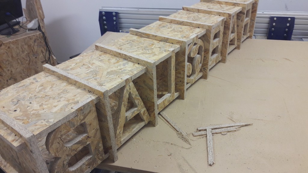
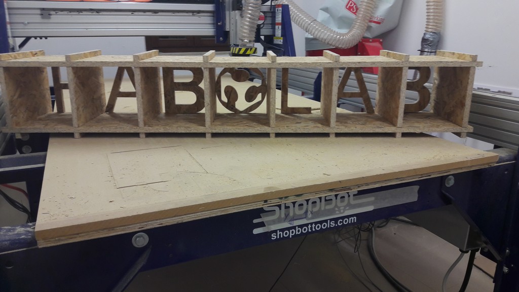
Upon an idea of one of my colleagues, I designed a shelf-like expositor with the Fab Lab write.
I designed all the single parts in SolidWorks, then used an assembly to verify the correct joining of the part.
I then exported all the faces, for doing a lasercut pressfit kit.
To scale down the model you have to use a simple ratio: in this case i modelled using OSB with a thickness of 18mm, while for the small model i used plywood with 5.1mm thickness.
So the small model is 5.1/18 = 0.2833 = 28.33% of the big one.
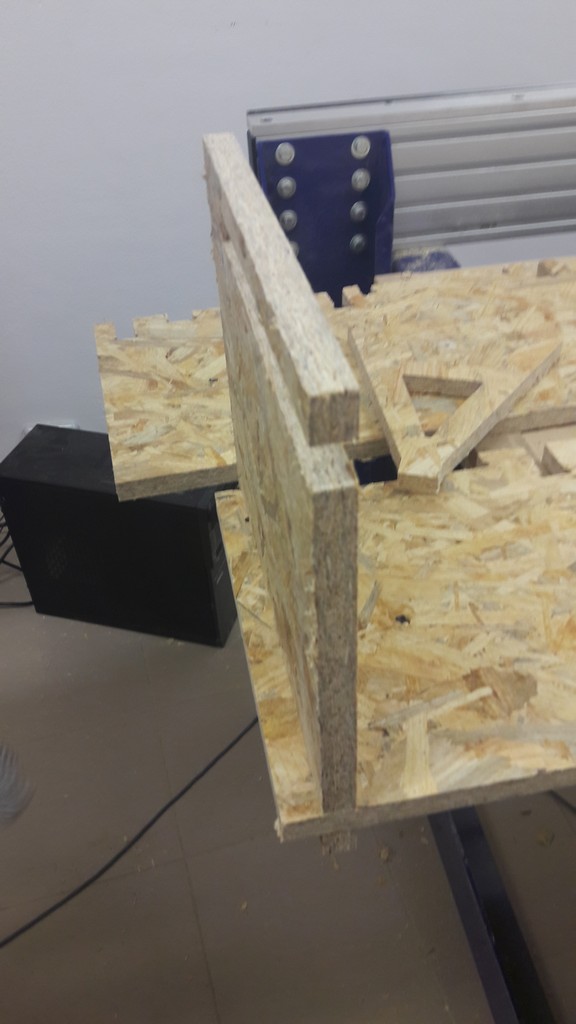
Unfortunately, i then realized that there was a mismatch in the walls measure (one of them broke in pressfit), and they weren’t fixed with the two bases.
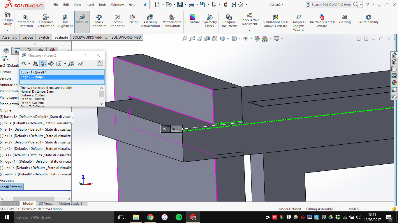
Having to redesign this I followed my instructor hints to move the letters and the logo on the back, and to do wider bases.
The assembly has a total area of 1.76 m^2 (calculated by solidworks), so it fits the wood board we are using (2.40 m x 1.25 m).
4. Cutting
Now it’s time to cut everything with the ShopBot PRS Alpha we have in lab.
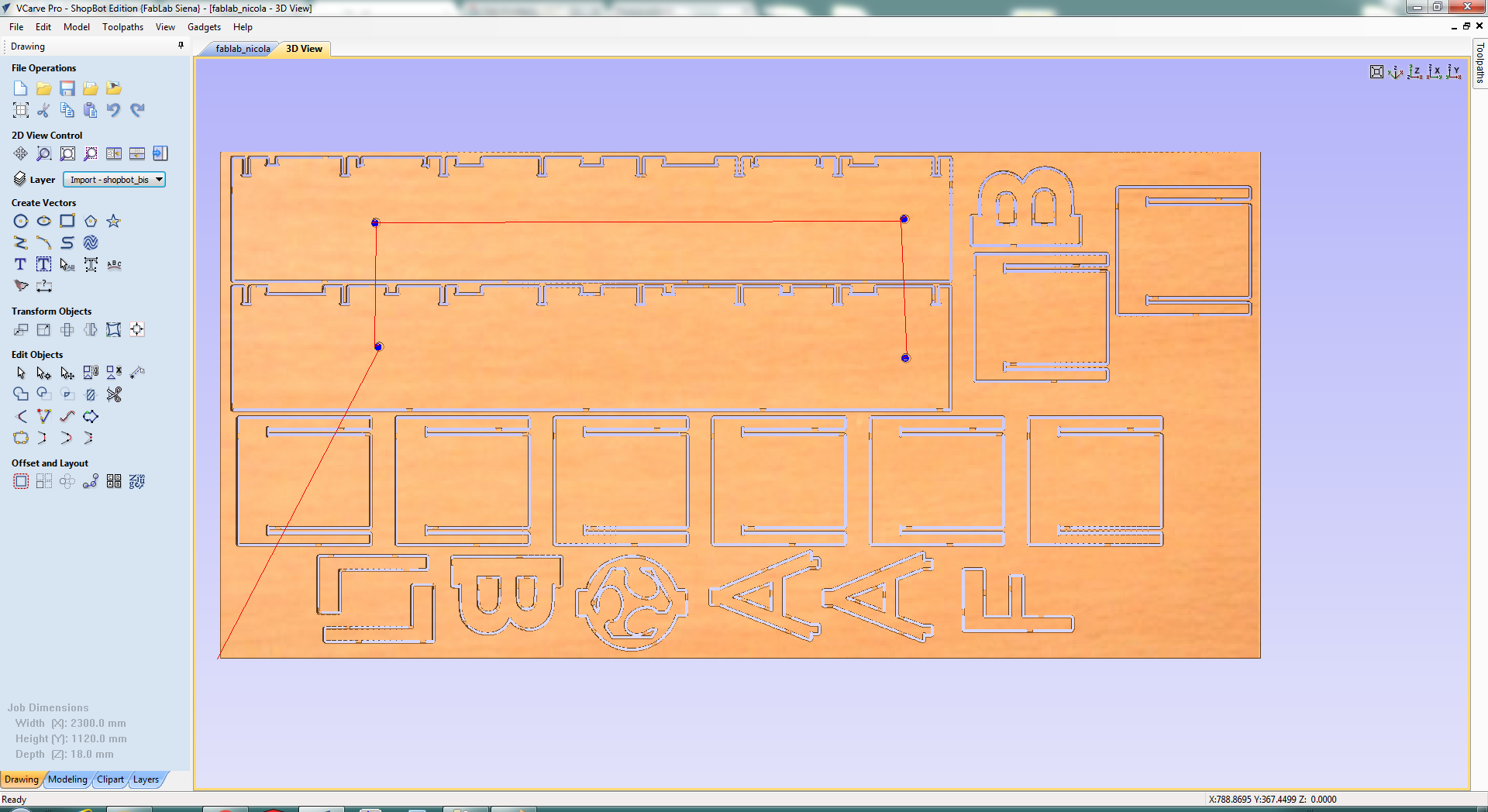
First using VCarve you have to generate the toolpaths the machine will actually cut, based on the vectorial file you provide it (a toolpath file is basically how the end mill should move, using X,Y,Z parameters).
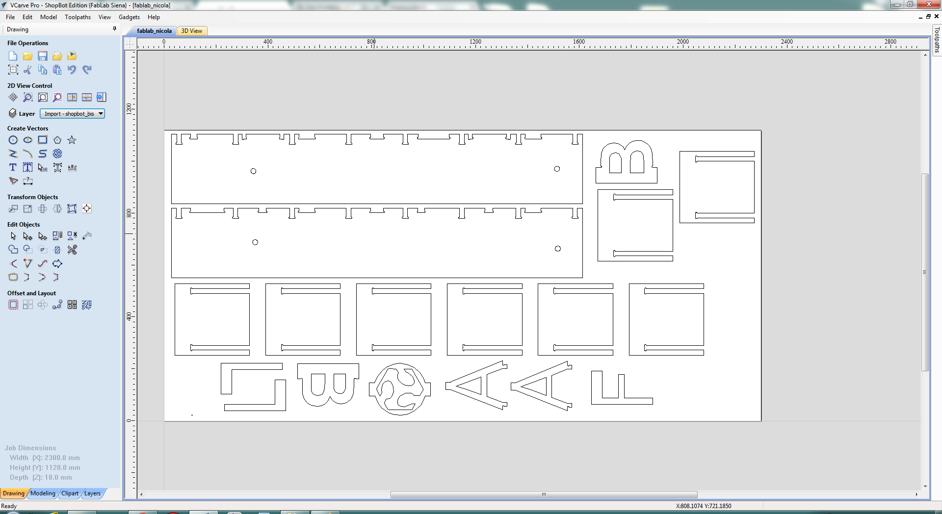
So I loaded the vector file with all the shapes in it.
Tip: you can export a face from solidworks directly by right-clicking the face and by selecting “Save as DXF/DWG”
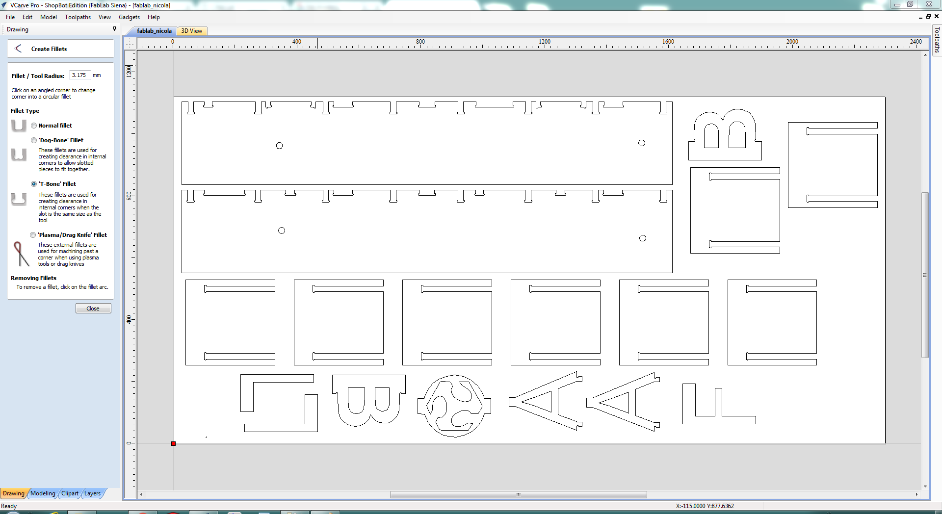
The curves in the file must be joined: you can join them using Illustrator (ctrl + j on the curves) or directly via Vcarve.
Also, you need t-bones! You can design them or use the function of VCarve to place them.
(care, as when inserting t-bones you are asked for the radius of the tool, not the diameter)
You can see circles in the above screenshots: with one of my colleagues we put 10mm circles in and then created toolpaths of them, carving them in the board: I used these to put screws and washers for fixing the board (also, I put some screw in the border of the table), as the board may move while the machine is operating.
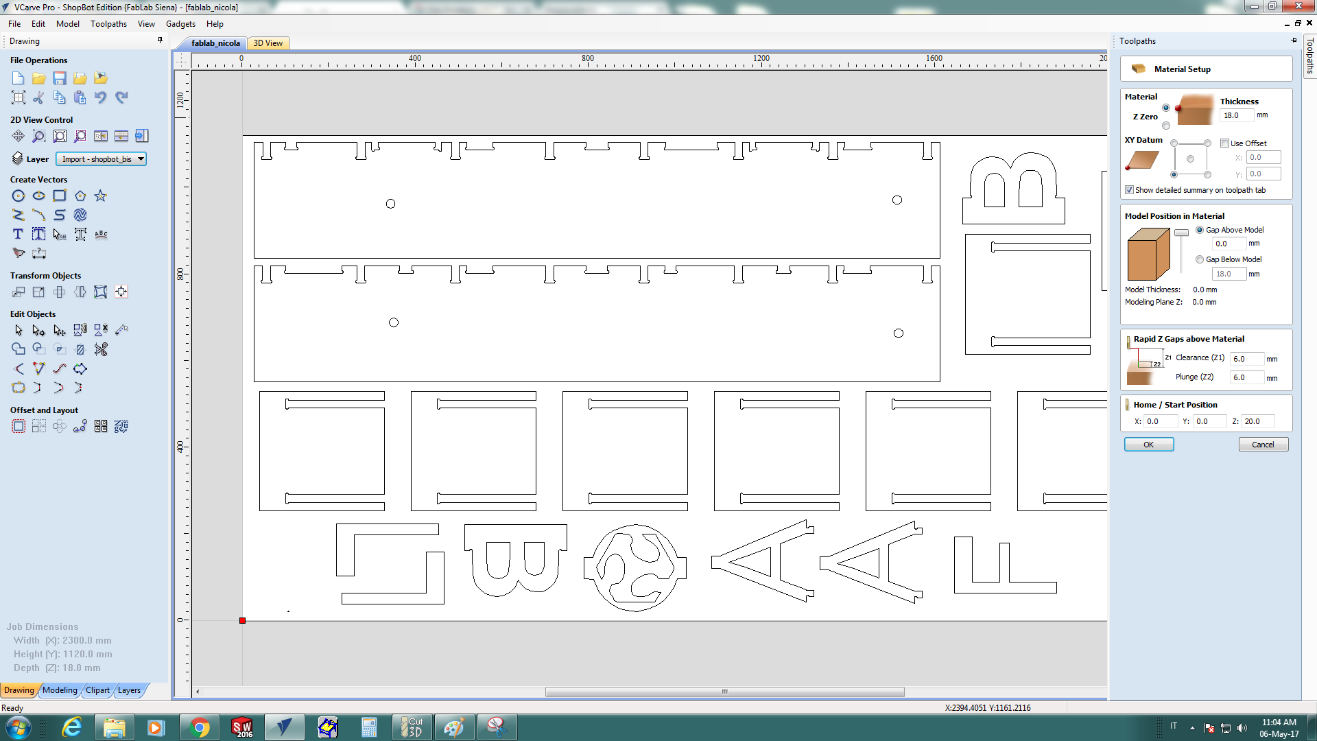
Then I set the material properties: the cutting depth I used was of 18.1mm, while the board is OSB of thickness of 18mm (0.1 mm in plus is enough to be sure that the wood is being cut).
You can now generate the toolpaths and preview them:
 Screw hole toolpath
 Inside toolpath
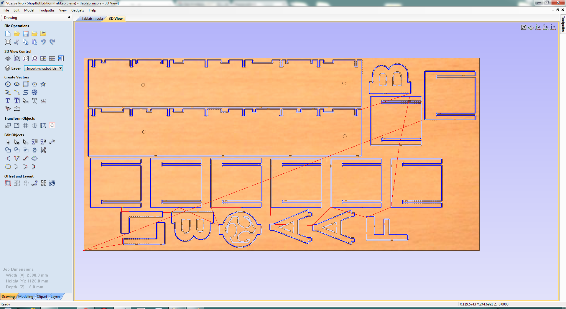 Outside toolpath
I used a 52-910 1/4 inch (6.35mm) end mill.
An important parameter of VCarve is the feed rate: it’s at which speed the machine works.
If it goes too slow, there is a risk of fire (the friction maybe lead to combustion) and too fast may lead to early deterioration of the end mill.
It’s based on a simple calculation:
feed rate = RPM x # cutting edge x chip load
where:
- RPM: rear per minute of the end mill, in this case 12’000
- # cutting edge = number of cutting edge of the end mill, in this case
- chip load: how much the aspirator take off the waste while working; this value is found in a table with an entry for the end mill, in this case varying from 0.007 to 0.009 and i chose 0.008
I, anyway, used a feed rate of 70, because it was found that is a good feed rate!
There are some preliminary actions to do, before the effective cutting: first you need to check the end mill (the one that was in the machine was broken), so we proceeded to change it.
Then, if needed, you have to heat up the spindle (if the machine has not worked for some time), from ShopBot Control Panel:
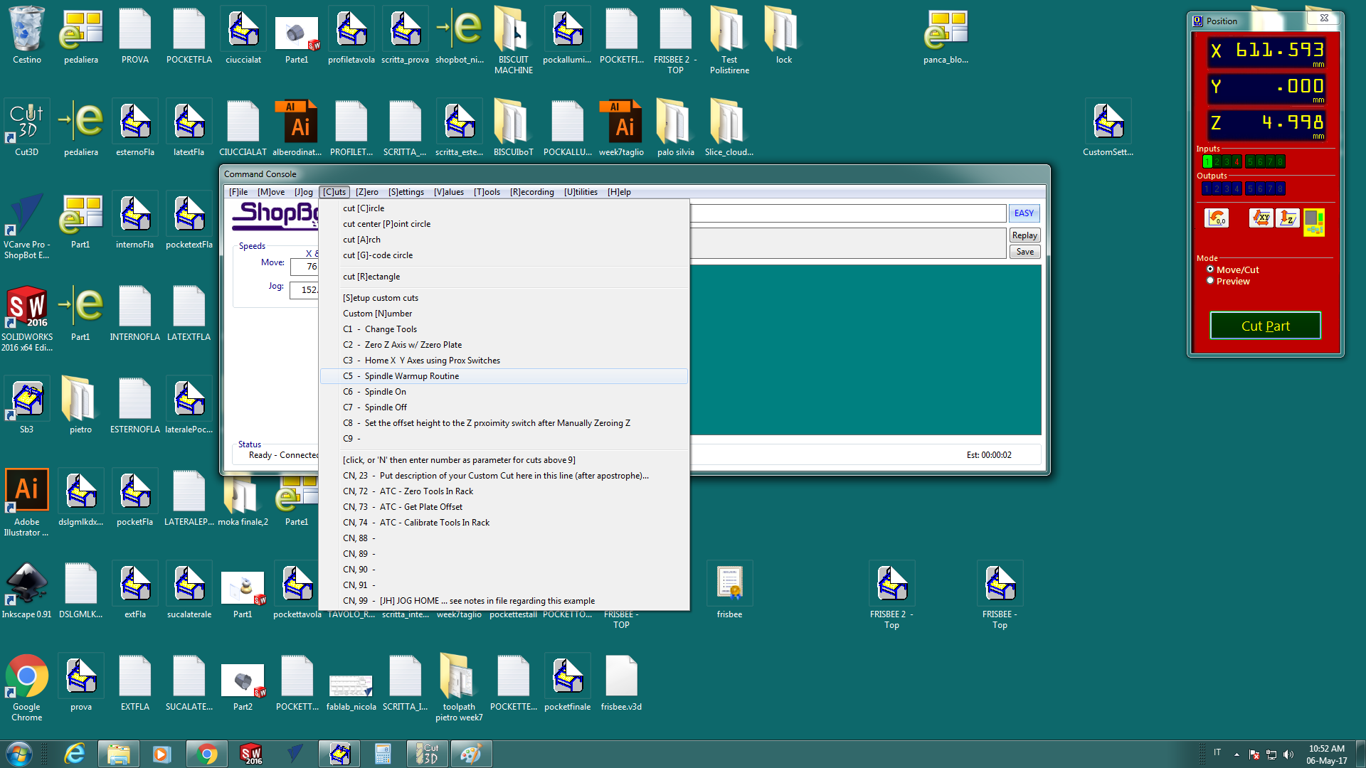 C5 - Spindle warmup routine
Now you can set the X-Y-Z zero.
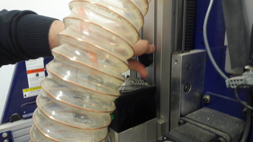
To set X-Y you simply position the spindle using the keypad. While to set the Z zero you can use what they call the “Zero plate"
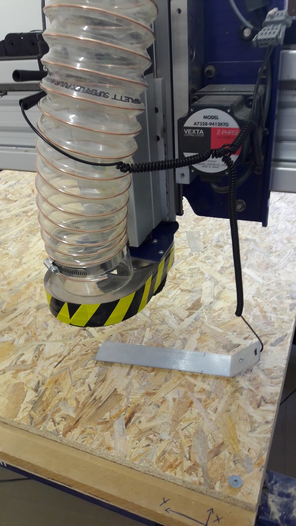
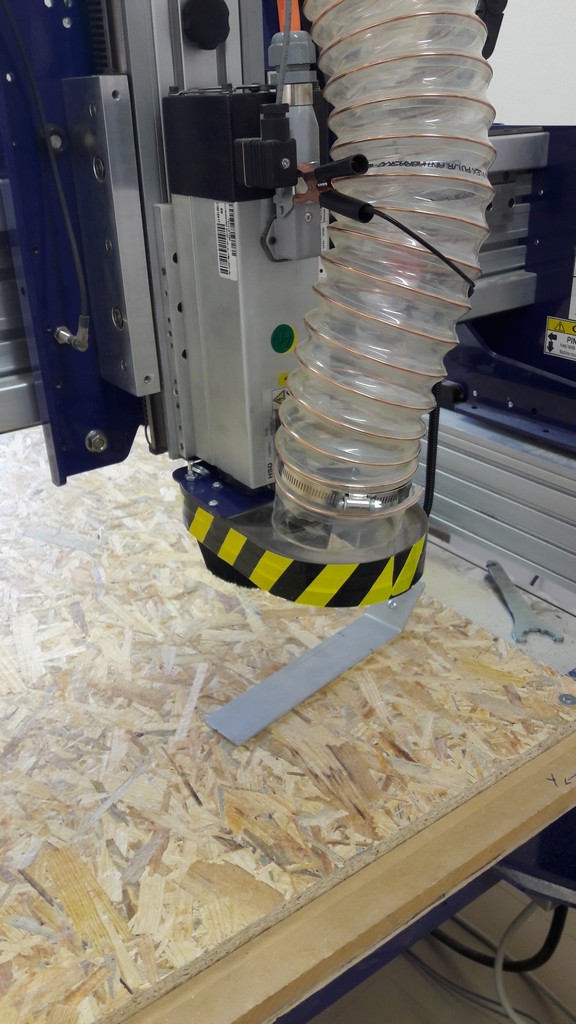
You plug che alligator clamp as the pictures, then put the metallic plate under the end-mil and run from the Shoptbot panel the apposite command:
 C2 - Zero Z Axis w/ Zzero plate
Remember to remove the plate before cutting!
Ready to go: first we cut the inner toolpath (the inside of logo, a and b in my case) (tip: in Vcarve this is a “pocket toolpath”) and then the outer toolpath.
Photo of work in progress:
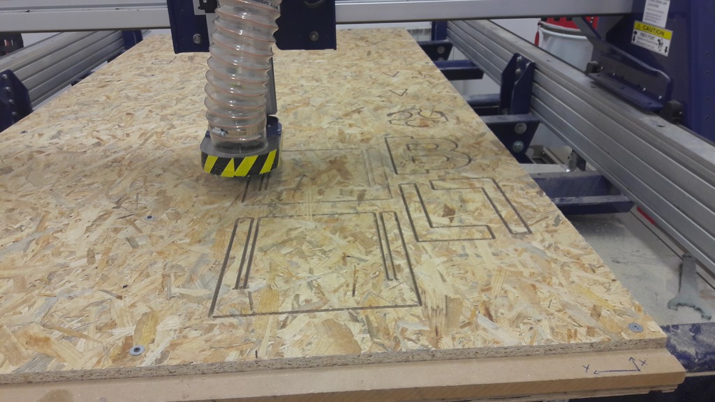
The cut runned for about 2 hours.
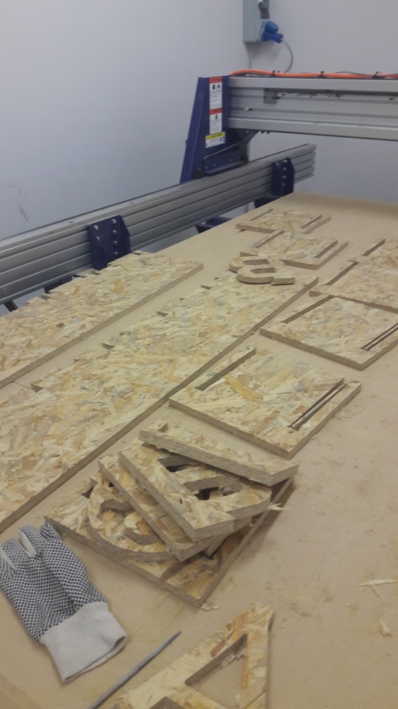
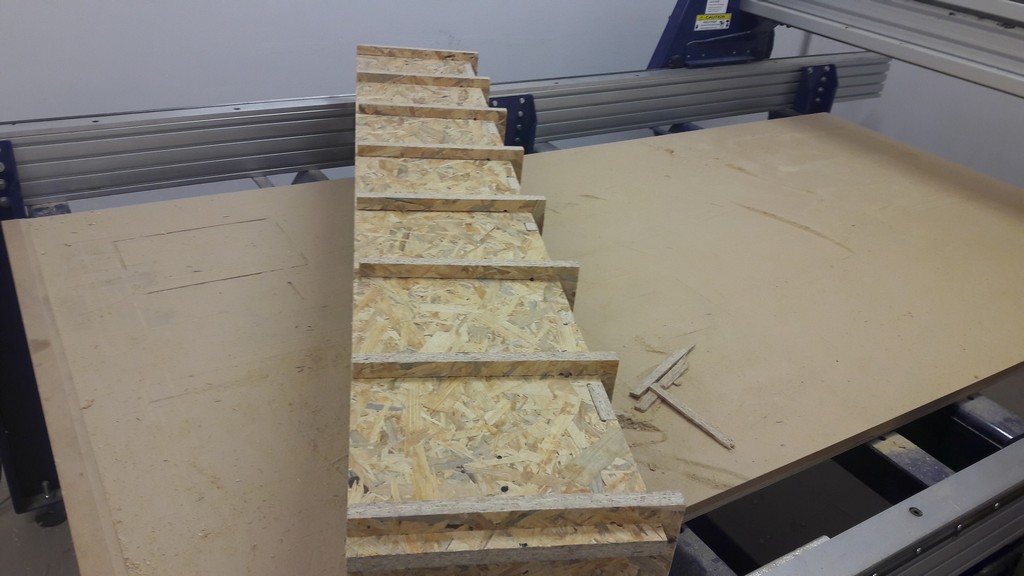
Then the assembly process, that incredibly went smooth: after polishing (with sand paper and a dremel) the pieces were fitted by hands or with a few hits of hammer.
A special thanks goes to SImone and Alessandro for helping me until 10pm!
5. Files
First design, SolidWorks files - .rar
Second design, SolidWorks files - .rar
Vcarve File - .crv