FAB LAB
Puebla

Embedded Programming
WEEK ASSIGNMENT:
-Read a microcontroller data sheet
-Program your board to do something, with as many different programming languages
and programming environments as possible
For the assignment I'm using 2 programs the arduino IDE, and the AVRDUDE as my programming environments.
As for my microcontroller I used the Attiny 85.
Attiny85
Now the attiny I've chosen is the Attiny85 in trough hole presentation, it's a small AVR of 8 pins 6 of which are I/O and the other 2 are supply ehich works between 2.7v-5.5v it has an internal clock of 1Mhz and using an external clock can reach 20 Mhz, and a flash memory of 8 kbytes it's also kind of the big brother of the Attiny25 and Attiny45 which are it's similar changing only the memory capacity.

ARDUINO
Starting with the IDE of Arduino we can program many types of processors using the ISP programming and any programmer out there, be it the usbtiny, fabisp or even an arduino itself. In my case I'll start by using an arduino board to do the programming as many people already have an arduino board more than a programmers, that way I can to show that you don't have to buy or even build new programmers for new ICs. After that I'll use my FabISP that I build during week 4.
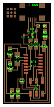
First step is identifying the important pins in our board for the programming both with the fabISP and the arduino board.
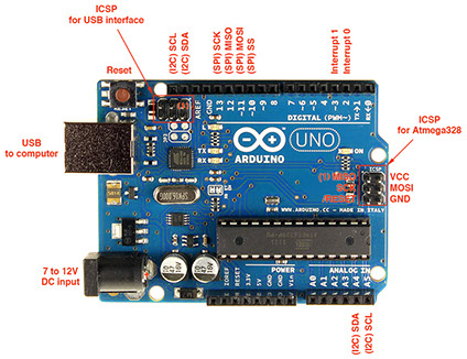
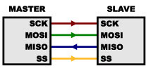
The ones we are interested in for this assignment are the ones for SPI communications which will allow us to program. In the case of the UNO we have them in the digital pins from pin 10 to 13 and on the lower side of the arduino, where they are bundled together as ICSP you can see them in the image to the lefts, for the FabISP it also has the ICSP where J1 is as you can see on the iamge to the right. However what do this pins mean. Well they're part of the SPI communication protocol which operates with the clock to transmit information, in this type of communication there's a master and a slave which basically means there's one which gives orders and on who follows where SCK has to do with the clock signal the master is giving, MOSI which means Master Out Slave In thats basically the master giving it's info, Master In Slave Out where its the other way and finally SS which is the slave select basically telling which device becomes slave. As the image below represents.
This information is important because in the arduino IDE there's an example code where you transform the arduino to ISP(in system programmer) which makes use of this protocol to be able to program, and the FabISP is a porgramer by default.
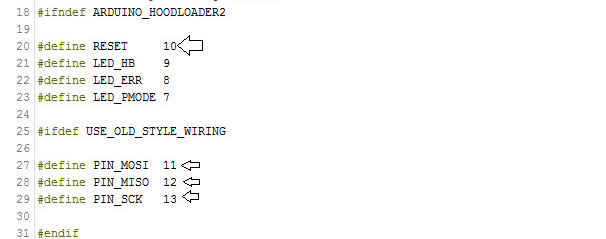
In the code to convert the Arduino as ISP you can look at the pin out here.
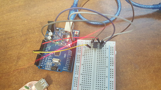
Let's start with our arduino. So now that we have our arduino board converted to an ISP we have to wire it to our new avr device we want to program. the wiring is simple enough, we will connect:
MOSI with MOSI
MISO with MISO
SCK to SCK
and just like our code told us
SS to Reset
in the case of our assignment that would be
Arduino Pin Attiny Pin
10 1
11 5
12 6
13 7
Also we musn't forget to wire commong grounds and give power supply to our AVR devices If like me you decide to use the board to supply it's convenient but not necesary to put a capacitor to decouple, in other words reduce electric noise.

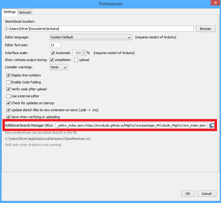
So after having the wiring done it's time to start programming. To program the attiny you must, first have the attiny library for the hardware, you can either make it which is by done by creating a new board file where you typically put, it's name, the protocols, which avr it uses, the fuses, etc or you can download it as it already exists. For new arduino IDEs this is just as easy as going to your arduino preferences, and pasting the URL of the new device in additional boards manager.
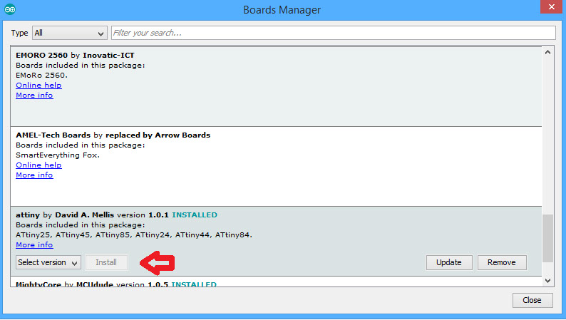
And then in Tools>Board>Boards Manager you just look for your new device and install easy as that.
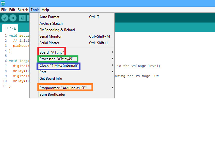
Now that you just finished installing your new device in your arduino, it's just a simple matter of uploading a program. To do this there's just a couple more steps. You have to select which device your using(marked in red), which variant or processor it has(marked in green), the speed of the clock which you are using(marked in blue) and that you are uploading this program using the arduino as n ISP or you'll be programming your UNO instead of your attiny.
And now you are ready to go and upload your blink test.
AVRDUDE
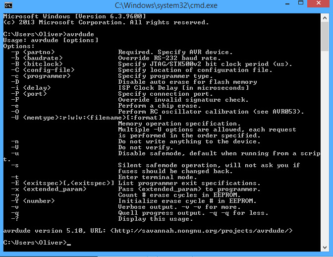
AVRDUDE is a command-line tool, so, in order to use it, you’ll need to open up the “Command Prompt” (Windows) or “Terminal” (Mac/Linux).
Now for Avrdude the wiring process is the same where things change is how we program. Avrdude is a command line program which runs from the command prompt, the basic commands are the ones in the next window, as I have alredy talked about a bit of avrdude in previous assignments I'll skip directly on how to upload a program.
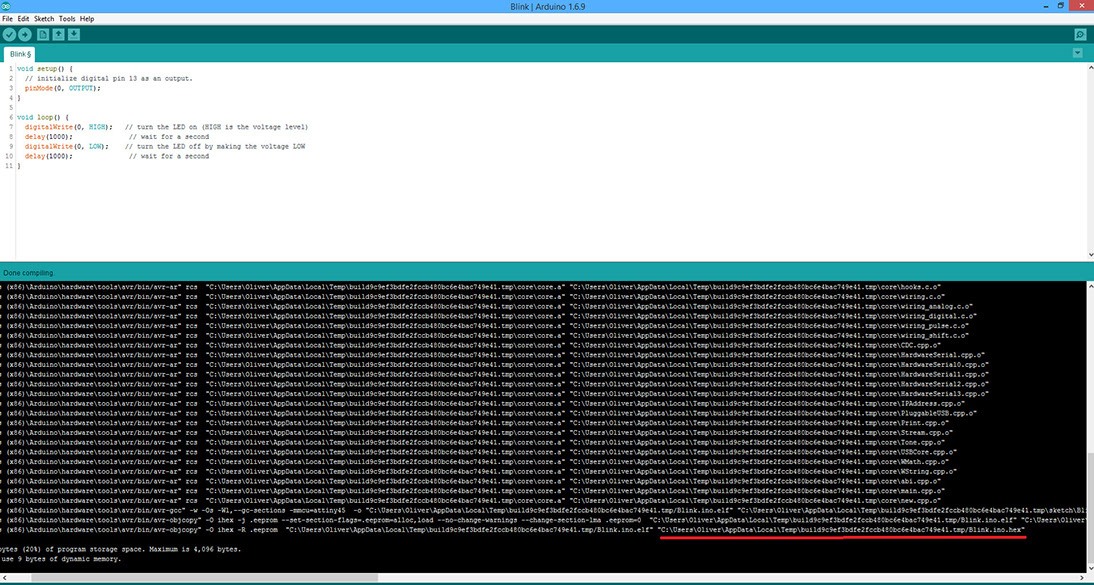
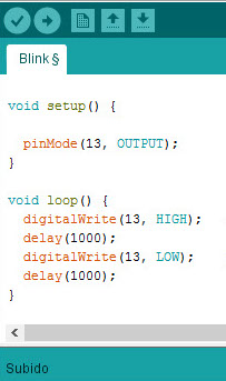
AVRDUDE is designed to upload .hex files, to get them you can use any AVR programming tool as my main is arduino I'll show you how to get it from there. When you compile the IDE will make all the necessary files to upload the program on of them is the .hex, however it's normally saved in temporary files so to find it we must activate the compilation verbose and when we compile it will show us all the locations of our files. I used a simple blinking code shown next made with Arduino IDE shown next, and I've underlined the location of the .hex file I need.
void setup() {
pinMode(0, OUTPUT);
}
void loop() {
digitalWrite(0, HIGH);
delay(1000);
digitalWrite(0, LOW);
delay(1000);
}
Having that the command line I would be using would be the next one making sure that my .hex is in the same directory I'm working with. In the example.
avrdude -c stk500v1 -p t85 -P\\.\COM20 -b19200 -U flash:w:blink.hex
To give a better idea of what line of code is I'll go trough all the commands.
-c stk500v1
This part defines the programmer, in the assignment i used AtmelsSTK500 but there are quite a few for example, avrisp, usbtiny and usbasp
-p t85
This is just to tell it what microcontroller its programming in this case t85 refers to an attiny85 another example would be m2560 for the mega 2560.
-P\\.\COM20
This is the communication port to use to talk to the programmer in my pc it was port 20 but this would differ from PC to PC
-b19200
This is for overriding the serial baud rate for programmers like the STK500 which in here I'm using. However normally the default is correct.
U flash:w:blink.hex
This one is the most important command as it's the one programming. It can be either flash or eeprom, then we have the r/w/v which are (read) w (write) or v (verify. And finally we have the name of the file we are reading, writing are verifying.
In my case i wrote flash:w:blink.hex that means my file will write in the flash memory the file with the name blink.hex.
So now we upload.

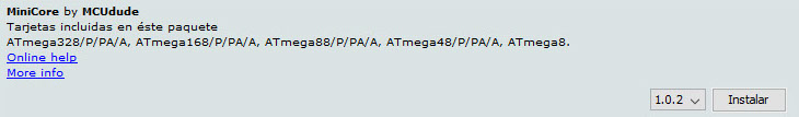
Now we pass onto our FAB ISP this time I decided to do it differently programming it directly from Arduino IDE, for this I needed to add the 328P by itself to the compatible devices used in the IDE(I could bootload it and work it as arduino but it uses extra memory). To do this I used the MiniCore made by MCUdude. This contained the necessary configuration to be able to program my 328p by itself.
Now I choose all the necessary configuration to program it. The clock which I use(16MHZ), my vairant which is a 328p, a low BOD(brown out detection), the correct port and my programmer.
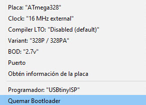
Then I upload a simple blink example, shown to the side.
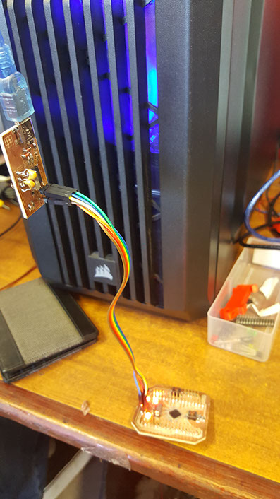
Video of board working