FAB LAB
Puebla

Electronics Design
WEEK ASSIGNMENT:
-Redraw the echo hello-world board, add (at least) a button and LED (with current-limiting resistor check the design rules, and make it
Eagle
As i studied mechatronics circuit design, is something i have experience with and after trying various softwares like Proteus, Kicad, etc. I've found that I'm the most comfortable designing circuits using eagle. However I'm also quite fond of proteus thanks to it's simulator software even if it crashes half of the time I use it and sometimes runs the other half. Because when it works it's beautiful.
Attiny85
Now the attiny I've chosen is the Attiny85 in trough hole presentation, it's a small AVR of 8 pins 6 of which are I/O and the other 2 are supply ehich works between 2.7v-5.5v it has an internal clock of 1Mhz and using an external clock can reach 20 Mhz, and a flash memory of 8 kbytes it's also kind of the big brother of the Attiny25 and Attiny45 which are it's similar changing only the memory capacity.

Using this micro-controller I started designing my circuit, before going into the program itself and as a rule, I always ask myself what's needed. In this case the requirements of my circuit were one led, a reset button, a way to program it and pins to work with. So with that in mind I drew this sketch in eagle.
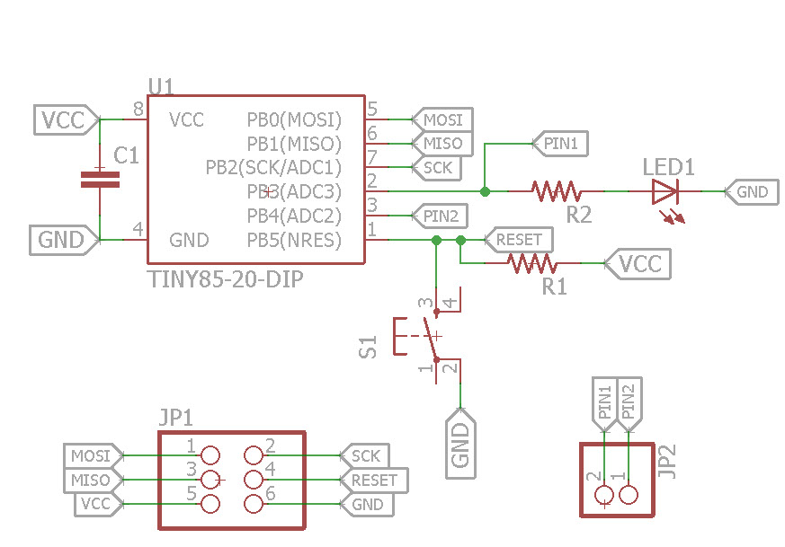
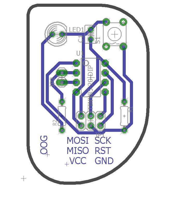
Inspired by arduino boards I used 6 pins for the ISCP and then left two more pins as extras, however the ICSP pin can also be used for other uses than programming. Basing myself on this schematic I passed on to the board. Which as all components where trough hole i worked with the bottom layer so components would be on the other side.
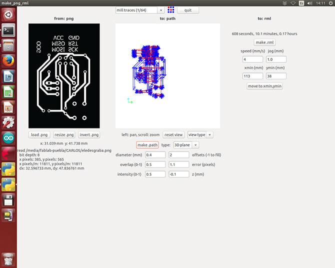

Using the exported png from the board I used the milling machine to fabricate them, I know I used FR4 however that's the one that is available to buy in Mexico.


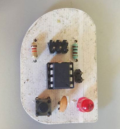
And then I soldered it to finish it

I did this one yo use the attiny, however i also decided to design a board using an ATMEGA328p, as I wanted, more pins for my projects.
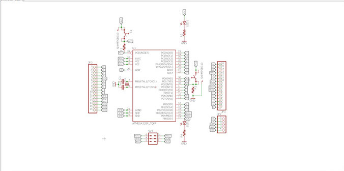
ATMEGA328p
This one come in an SMD presentation, it's a medium sized AVR of 32 pins 23 of which are I/O and the other 2 are supply which works between 2.7v-5.5v using an external clock can reach 20 Mhz, and a flash memory of 32 kbytes, also for communication it has one UART and one TWI. It's also the most common one used in commercial boards.

For the design i decided to add 2 leds one which shows it has a voltage supply and the other one connected to a pin, I also added 2 buttons, a Reset button and one integrated to a pin. I'm using an external 16 MHZ crystal with two 22pF capacitors to make the oscillator circuit , and the respective resistors for the leds and buttons. The sizes for the resistors and capacitors I used were 1206 as this was the size i was the most comfortable soldering. Finally I used pins to every pin so that i could use them on them I also added extra pins for both GND and VCC, also extra pins for TX and RX so that i could communicate with the PC trough an FTDI and still be able to use them to communicate with external hardware such as bluetooth or another board.

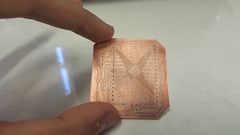
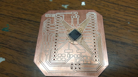
The board after milling, and starting to solder.

HERO SHOT
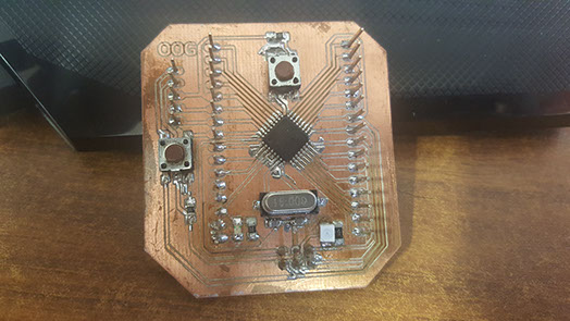
And her it is with a simple button application.
