FAB LAB
Puebla

networking and communications
WEEK ASSIGNMENT:
-Design and build a wired &/or wireless network connecting at least two processors
For this assignment i decided to use differente types of wired communications to demonstrate that despite how easy and similar they look each has its own pros and cons. For the first two i used a simple led turning on and off to demonstrate the communication for the third one i used a potentiometer to send analog data.
UART
So i started with an easy one which was UART communications, in which i used an my meg328p to communicate with a small attiny board. UART just required for TX,RX and ground of both processors to be connected and then using serial communication send and receive data between them. As the attiny didn't have hardware UART pins I used Software ones. For the communication the RX and TX on must be crossed between boards. So that when one board transmits the other receives. The attiny board was made for this assignment and has a simple button and led, and extra Pins for communication I2C I made three, In case I needed them.


For this first communication what I did was communicate the buttons of two boards so that when the attiny receives an Input it's send to the mega328p so that he can react and viceversa.
Code Mega328p
Code Attiny85


TWI(I2C)
This is just two wires, called SCL and SDA. SCL is the clock line. It is used to synchronize all data transfers over the I2C bus. SDA is the data line. The SCL & SDA lines are connected to all devices on the I2C bus. There needs to be a third wire which is just the ground or 0 volts. There may also be a 5volt wire is power is being distributed to the devices. Both SCL and SDA lines are "open drain" drivers. What this means is that the chip can drive its output low, but it cannot drive it high. For the line to be able to go high you must provide pull-up resistors to the 5v supply. There should be a resistor from the SCL line to the 5v line and another from the SDA line to the 5v line. You only need one set of pull-up resistors for the whole I2C bus, not for each device, as illustrated below:
For this communication the slaves(attinys) read signals and send them to the master(atmega328p) and he can show them.

Code Mega328p
Code Attiny85


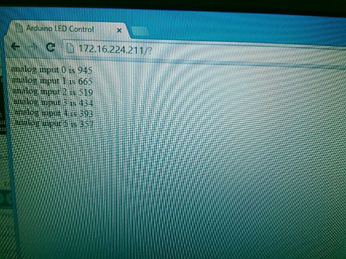
ETHERNET
The final communication I used was ethernet. I decided for ethernet as i had alredy used SPI from which ethernet is used. In this part i created a small webserver using HTML in my arduino IDE to sense analog inputs from a potentiometer and send the data trough the web to my PC.