FAB LAB
Puebla

Electronics Production
WEEK ASSIGNMENT:
-Make an in-circuit programmer
Design
After reading a bit on programmers, I decided to try a new version of programmer different from the ones presented for the academy. One which didn't require me to solder and then desolder. After looking around for open source programmer i found the USBtiny from Adafruit.
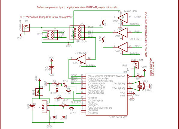
However even that one seemed to be a bit excessive on the needs i had. So I decided to simplify it a little bit. I started by changing the IC used to the one we were using for the assignment. Which was an attiny85. Using that change and knowing I could use the internal clock on my attiny I also removed the crystal. After that I removed the unnecesary bits that came with changing the IC. Such as the leds which didnt have pins to connect anymore, and the level shifters because my attiny could work with 5V. All in all i ended with the next schematic.
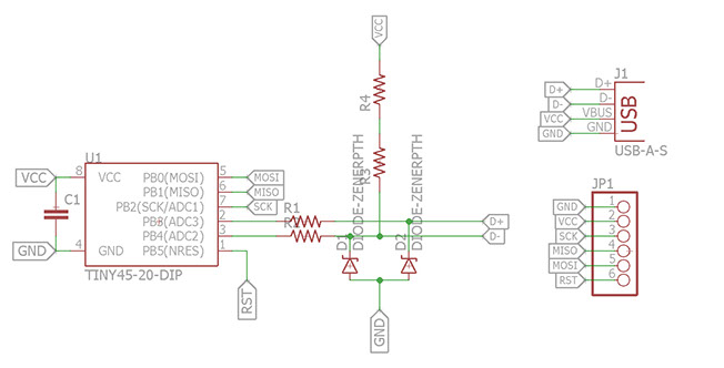
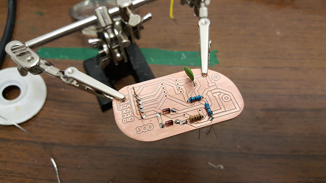
Using this schematic I created my board. As i didn't have the all the exact resistances I use two in series also as I didn't have SMD components i did it with trough hole components.
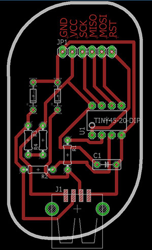
Using this schematic I created my board. As i didn't have the all the exact resistances I use two in series also as I didn't have SMD components i did it with trough hole components. The parts i Used where:
1x ATTiny45 DIP08
1x 0.1uF capacitor (104)
1x 68 ohm resistors
1x 1.5 k ohm and 200 ohm resistor to make a 17.kohm
2x 3.6v zener diodes
1x 6 pin headers row
1x USB conector
Production
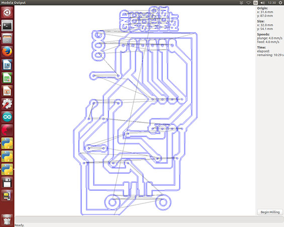
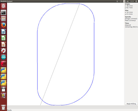
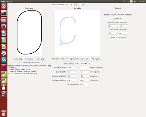
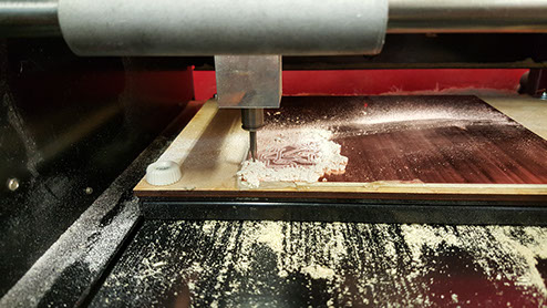
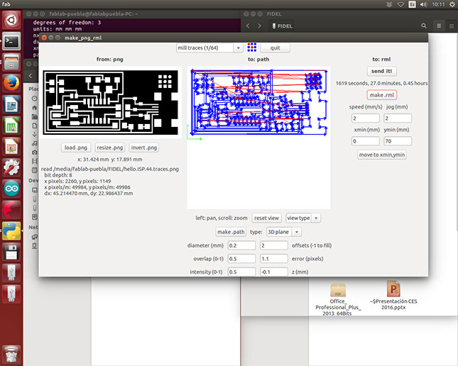
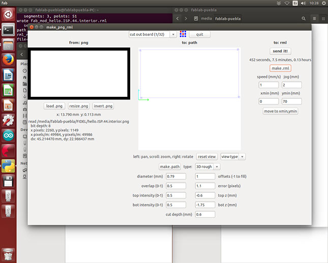
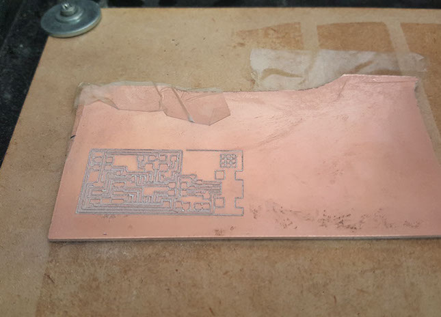
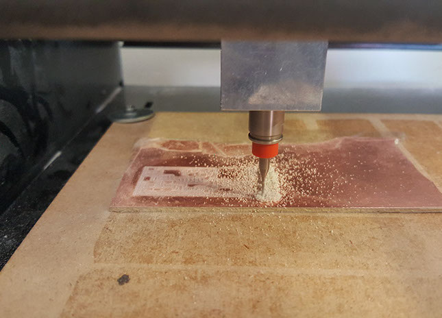
Now that i had my design it was time to get producing. Normally I'm quite fond of using etching as I feels it leaves a better finish, however it's due to it being a small circuit i decided to use our CNC milling machine for faster results. For the mill itself I used the FaB Modules. To do the paths I added a 1/64 V tool, for the parameters i only did 2 offsets because I don't quite like the finished product of many offsets and I'm quite sure of my soldering skills. As for the speed I used the defaults it had. For the cutout I used 1/32 mill, and kept all defaults except for the depth of cut which i made slightly bigger.


After that i give it a nice soft sanding to remove any burr that might have stayed on the circuit. So it doesn't short or malfunctions in any way and finish it with a nice cleaning with some alchohol. After that I start soldering, unfortunately it was at this point that i had done a mirror of my circuit and had to solder everything on the copper side of the circuit.
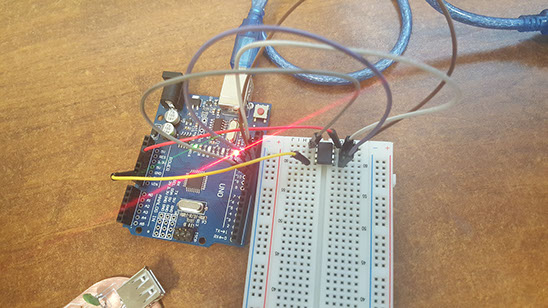
When i was almost finished soldering I remembered i needed to program my attiny as a programmer. So using AVRDUDE and an arduino I started programming
I first programmed my arduino as an ISP programmer using the example code in the IDE. After that I connected my Attiny to my arduino MISO with MISO, MOSI with MOSI, SCK with SCK and Reset to PIN 10. However unlike the diagram I forgot the decoupling capacitor, OOPS however it seemed to not matter in the end.
Now for what i used to code it was the USBtiny.hex provided by Adafruit and the method to load it into my attiny were the next two.
avrdude -c stk500v1 -p t85 -P\\.\COM20 -b19200 -U flash:w:usbtiny.hex
avrdude -c stk500v1 -p t85 -V -P\\.\COM20 -b19200 -U lfuse:w:0xe1:m -U hfuse:w:0x5d:m -U efuse:w:0xff:m
Now for a deeper explanation on what everythng means specially as it's in in the command window which is scary to quite a few people I'll go step by step. First avrdude is the main command. -c is the programmer used in this case the arduino uses the stk500v1 protocol, -p specifies the type of avr in my case the attiny85 -P represents the port used by the programmer in my pc it was COM20, -b represents the baudrate to be used again in case of the arduino this is 19200 bauds, -U represents the memory operation, in this example a memory flahs where i write my hex file. Now finally burn the fuses making this a one time program unless i use a high voltage programmer to try and reset it.

Testing
Now that the programming is well and done I can finally finish soldering my circuit Druing this phase, SMD components hadn't arrived as there were some import issues.

Now that all is said and done I decided to try and program a simple blink on another attiny to test my circuit. So I downloaded the driver from the ADAFRUIT page, and using again AVRDUDE I tried my programmer this time with the next command line:
avrdude -c usbtiny -p t85 -U flash:w:blink.hex

And .... it worked!

I also built the FAB ISP this time using SMD components.
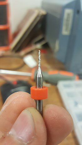
First I did the milling with an end mill tool of 0.2 mm diameter, with 2 offsets and a depth of .1 mm
Mauris sit amet tortor.2
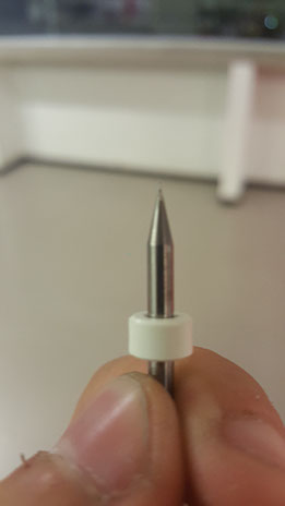
MILLING TOOL
CUT OUT TOOL
Finished Mill
Process of Cut Out
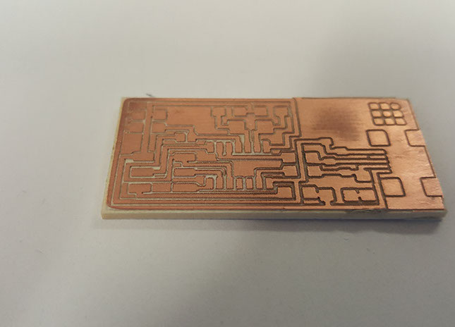
Finished PCB mill and Cut Out
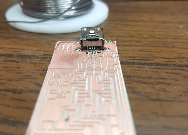
Soldering the mini USB port
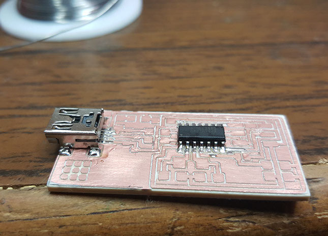
Soldering the Attiny 84
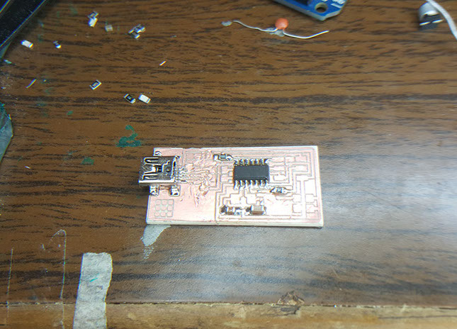
Soldering Capacitors and resistors
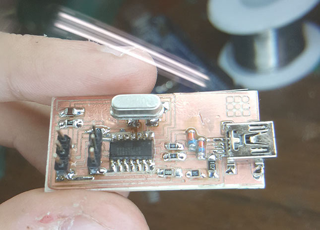
Finished Product, I lost my SMD crystal so I used a trough hole one adapted to my board.
<
>
Final Product

After that following the instructions I modified the makefile and programmed it.
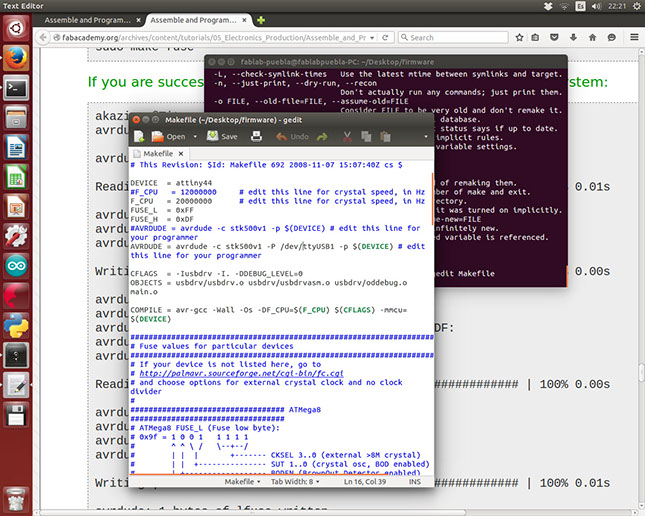

Modyfying the Makefile
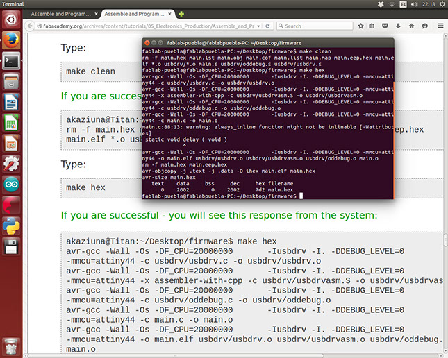
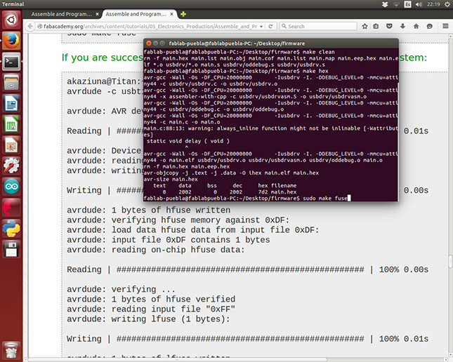
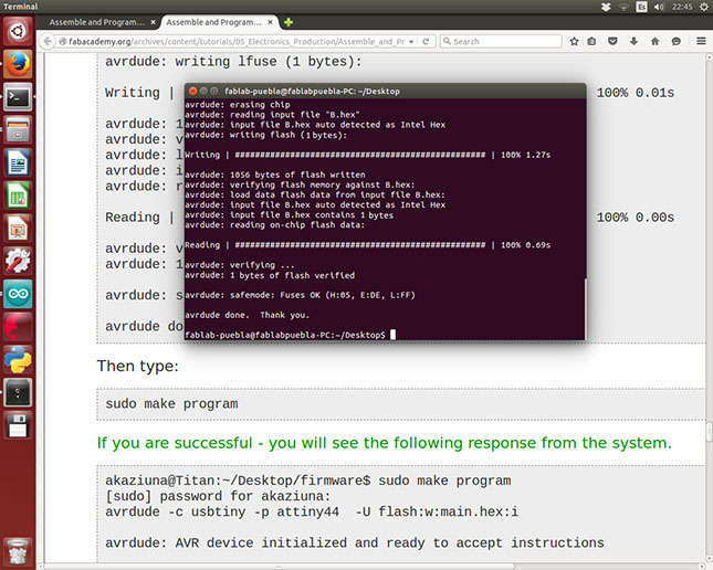
Programming
Programming
Programming
Programming
<
>