FAB LAB
Puebla

Computer-Controlled Machining
WEEK ASSIGNMENT:
-Make something big
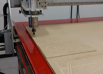
For this weeks's assignment I'll start with the equipment and how to use it. To start with here in Fablab Puebla we have the
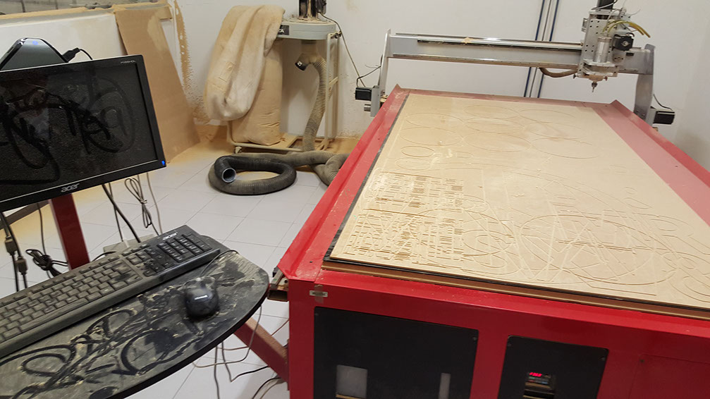
This router is a system that allows control at all times the position of a physical element, usually a tool that is mounted on a machine. It serves to obtain parts with certain measures, as well as to create programs that repeat with great precision pieces of equal size and measures to verify something that has been made.
The way that the movements of a CNC router is programmed using a language called "code-g" are plotted in 2D vectors, from programs like autocad, illustrator, LibreCAD ... supported file formats with this machine They are .PDF or .DXF.
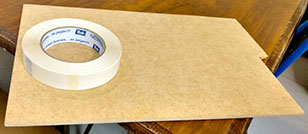
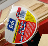
The materials needed to work with the Router CNC is double-sided tape highly aggressive (in this case a Tuk mark was achieved), the piece of material you want engrave or cut and file .DXF to work in the computer. a piece of MDF 30x20 cm was used for this practice.
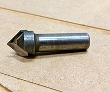
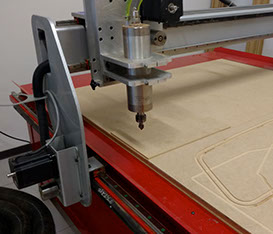
For the type of engraving or cut that is desired, different cutters (indexable edge that can cut side).
The cutter was used in this practice is one tip in "v", as shown in Figure 2.
The program used to manipulate the .DXF file before being sent to the CNC Router is "Vectric". This enables the latest specifications and adjustments to make good cutting or engraving.
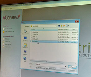
The first step is to open the DXF file in the Vectric program.
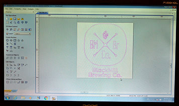
Once checked that there neither open nor duplicate vectors, the file will look like in the picture 7. The image will turn pink and stippled, indicating that the file is ready to be sent to the CNC Router.
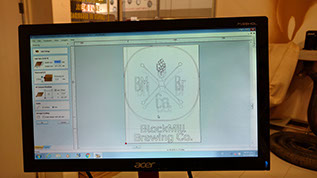
An example of 20x20 cm .DXF file, which will be recorded in the MDF plate shown in this picture.
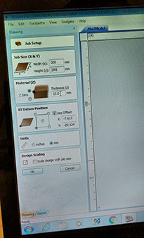
Following this, the specifications of the material which is to be cut or burn are given. In this case, the height and width (20x20 cm.) And the material thickness (MDF plate is 6 mm.)
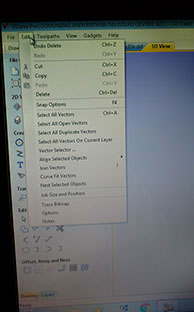
To send the file to CNC Router be considered as two elements; open and duplicate vectors vectors.
This helps eliminate the vectors are copied more than once, and to identify vectors that are open to close them.
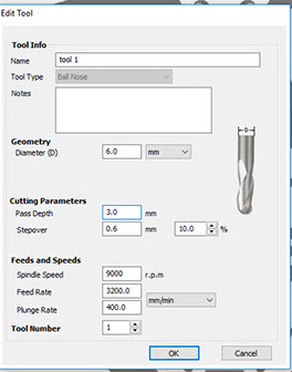
After that i chose all the tool details required for it to work
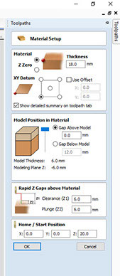
And the material Setup needed fo the machine.
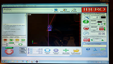
The next step is to apply the coordinates where the file will be cut, that the reason that the cutter does not leave the material to be cut or burn. To do this, simply move with the arrow keys of the computer to the point where you want the job done.
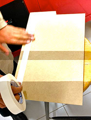
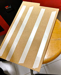
The material to be used to cut or record must be attached with double-sided quotation on the surface of the machine.
The purpose of this step is to make the material move from place when the CNC Router is working.
In the image shown how it should be designed the material to be cut before sending the file to the CNC Router and begin the process.
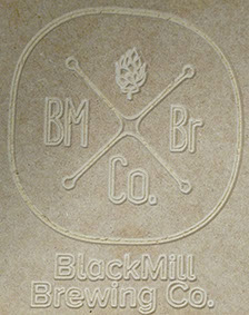
When finished cut or burn, simply plate material is peeled off and take away the pieces of double-sided tape that were previously stuck.
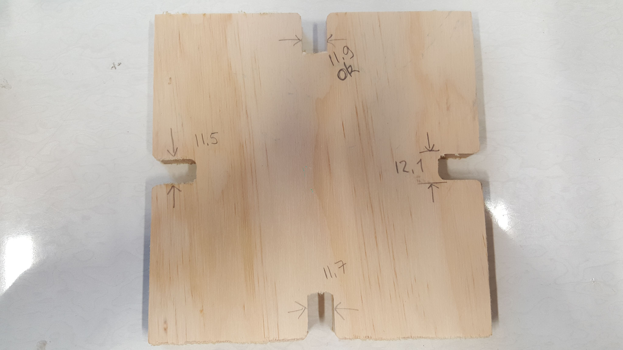
In the picture the end result of the work done in the CNC Router shown. The design was cut but not recorded.
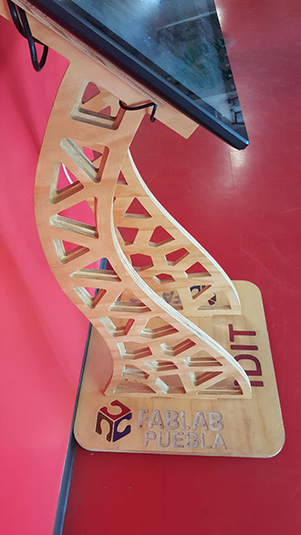
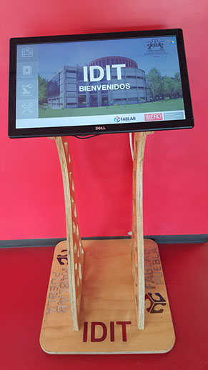
After explaining the process of how to use the machine I now started the work on the big thing. One of the projects I have is the creation of a map for the installations in Fablab Puebla so i decided for a touchscreen, however I still needed to create the base for the touchscreen.
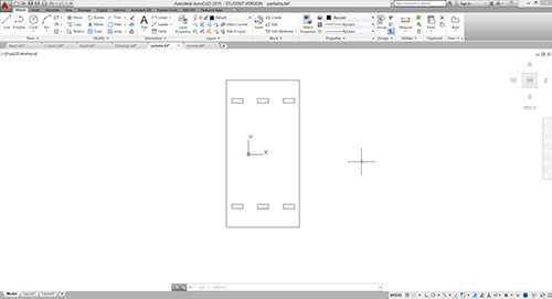
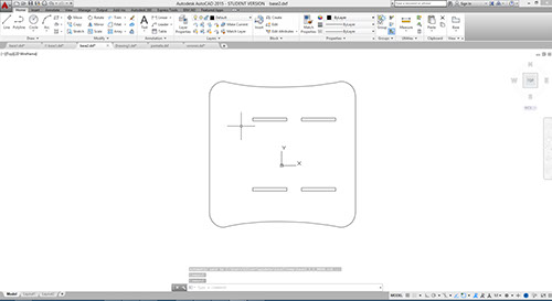
I used Autocad to design the base, it was composed of 4 parts, the first is the base for the touchscreen, the second are the side supports and the last 2 conform a base
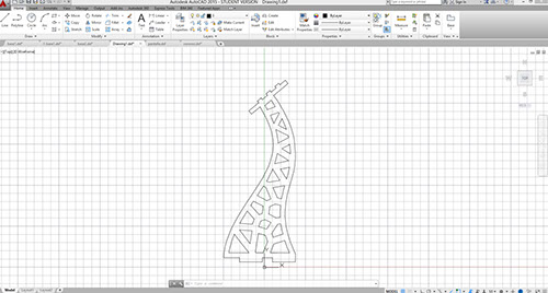
For the side support I used a style called voronoy
For the base i decided to do an engrave so i could pour colored resin so it could have a better look
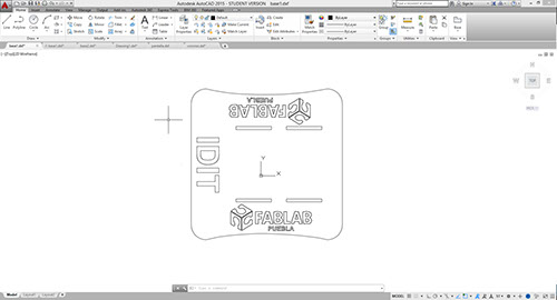
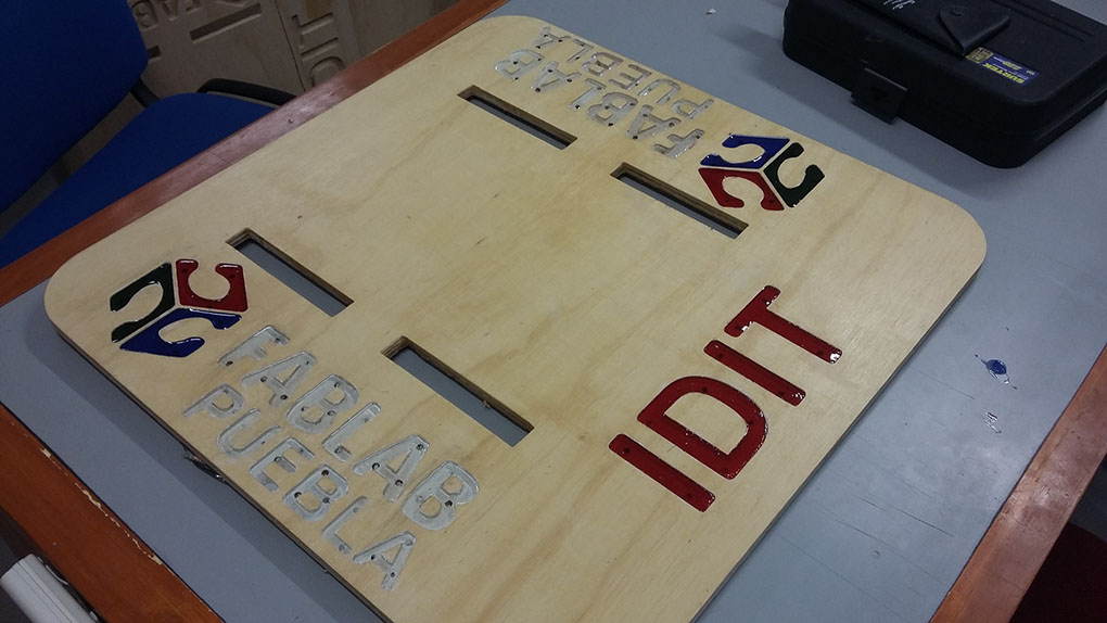
I also added leds to the letters so that the casting would shine