WEEK ASSIGNMENT:
- Measure something: add a sensor to a microcontroller
board that you have designed and read it
FAB LAB
Puebla

Output devices
WEEK ASSIGNMENT:
- Add an output device to a microcontroller board you've designed and program it to do something
This was a good opportunity to work on one of the projects I have with the university where I should elevate the energy to higher levels(from 5V the voltage used to feed to a range of 50-120v depending on the level selected) and be able to regulate it. It's composed of a microncontroller, 3 indicator leds, a potentiometer, a voltage regulator, a transistor, a small radial transformer and various passive components. I will be using this circuit both in Inputs and in the Outputs assignments. So the information on the circuit will be completed on the Outputs part.
I started by creating the schematic in eagle, in which I included all the components previously mentioned.
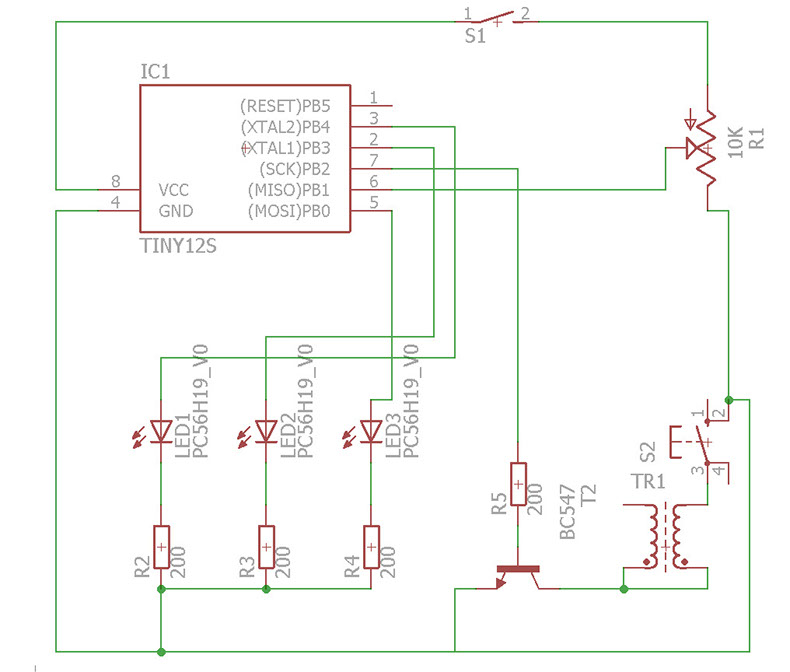
In the pictures below I show the board in both engraving and cutting formats so I could do them in the milling machine. I tried to use all SMD components however, both the potentiometer and transformer i couldn't find in SMD form, and due to it beign a prototype the miconcontroller is also trough hole so i can get it out easier to reprogram.


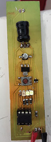
The next pictures show the finished product after milling it and soldering.

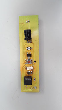
The next pictures show the finished product after milling it and soldering.
The code i used was one where it read the analog value from the potentiometer and it converted it into a value between 1 and 3 which decided how many indicators to light, and how would the transformer work. Thanks to the microcontroller datasheet I was able to identify the analog pin from my Microcontroller.

void setup() {
pinMode(0, OUTPUT);
pinMode(4, OUTPUT);
pinMode(3, OUTPUT);
pinMode(1, OUTPUT);
}
void loop() {
int input=analogRead(A1);
int powr = map(input, 0, 1023, 1, 3);
if(powr==1)
{
digitalWrite(1,HIGH);
digitalWrite(3,LOW);
digitalWrite(4,LOW);
}
if(powr==2)
{
digitalWrite(1,HIGH);
digitalWrite(3,HIGH);
digitalWrite(4,LOW);
}
if(powr==3)
{
digitalWrite(1,HIGH);
digitalWrite(3,HIGH);
digitalWrite(4,HIGH);
}
digitalWrite(0, HIGH);
delay(1/powr);
digitalWrite(0, LOW);
delay(1/powr);
}
Even though it may sound presumptuous I didn't have any problems during design of the circuit or the programming, as I heavily specialized in electronics during my college studies, the only problem which may not even be a problem were that I wasn't able to find only SMD components and I had to combine SMD with trough hole.
I'm using two types of Outputs the first one is the leds which react to the level of power measured in trough the analog signal from the potentiometer. The second one is a square signal which activates a transistor so I can switch my transformer and give the electroshock.
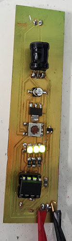
In the photos on the side we can observe the change in the leds due to the different power levels.
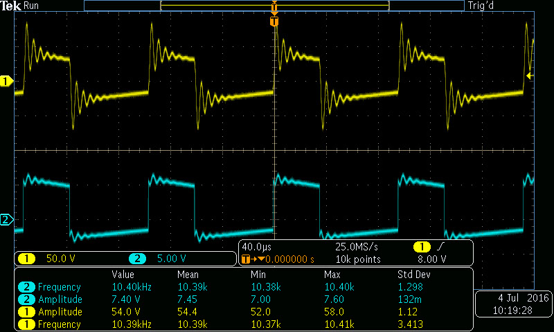
Due to it not being obvious the signals given from the transformer and the attiny I used an oscilloscope to measure them and show them.
The blue signal is the one given by the Attiny which is a square signal of 5v that goes to the transistor switching it, because the switching makes it so that the voltage is always up, because as we can see on the yellow signal after the first peak, the voltage falls. Also as we can see on the yellow signal the the voltage Peak to peak are around 100 V which is a nice voltage for the electro-stimulation. One of the problems I had with this part of the circuit was finding, the right frequencies to send, as sending them to high would be harmful, and sending it too low wouldn't give enough power.
Looking at the code again, we see that depending on the power level it will switch faster and just like pwm it makes it so that the faster the switch the stronger the signal.
void setup() {
pinMode(0, OUTPUT);
pinMode(4, OUTPUT);
pinMode(3, OUTPUT);
pinMode(1, OUTPUT);
}
void loop() {
int input=analogRead(A1);
int powr = map(input, 0, 1023, 1, 3);
if(powr==1)
{
digitalWrite(1,HIGH);
digitalWrite(3,LOW);
digitalWrite(4,LOW);
}
if(powr==2)
{
digitalWrite(1,HIGH);
digitalWrite(3,HIGH);
digitalWrite(4,LOW);
}
if(powr==3)
{
digitalWrite(1,HIGH);
digitalWrite(3,HIGH);
digitalWrite(4,HIGH);
}
digitalWrite(0, HIGH);
delay(1/powr);
digitalWrite(0, LOW);
delay(1/powr);
}
Video of it working, where i show the changes in the pulse on an oscilloscope. The video shows an arduino however it's only as supply for 5V