
Tapan
Betai

2016
Week-4 Electronics Production
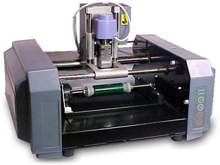
Starting with Ronald Modela Hardware:
- Preparing hardware for milling the circuit
- Cleaning the bed
- mounting the workpiece
- Changing the bit to 1/64 inch for circuit milling
- setting origin and setting z-zero
Photos needed to mill the circuit:
Image for milling the circuit with 1/64 inch bit
Image for cutting the outside border of the circuit with 1/32 inch bit
Image showing the components of the circuit
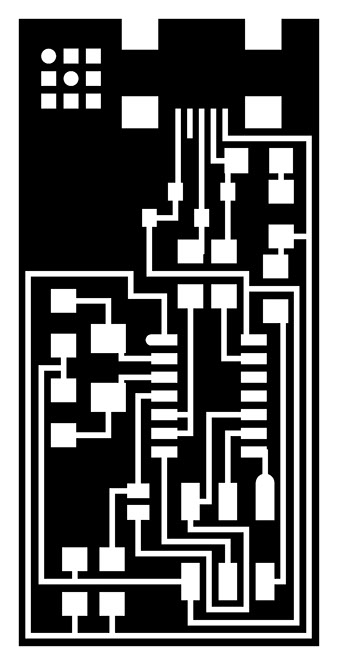


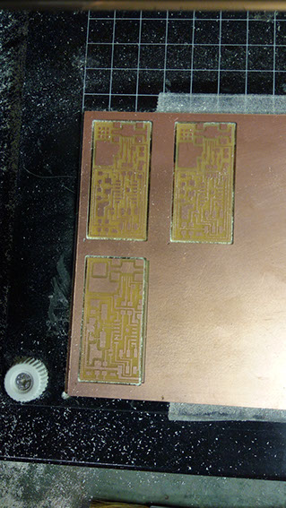
Different trials on milling machine
Components needed:
- microcontroller
- crystal
- USB connector
- ribbon connector
- Zener diode
- jumper wire
- firmware
- Resistors
- Capacitors
Needed equipments:
- Soldering machine
- soldering material
- magnifying glass
- holders for PCB
- flux
- small tips of soldering machine
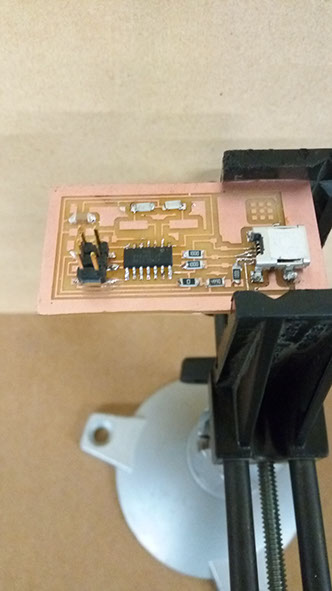
Soldering of USB power in First place
Soldering other components
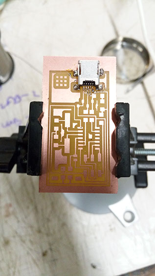
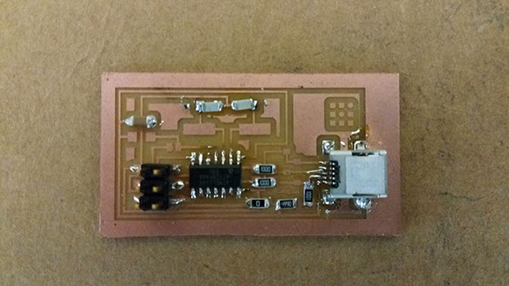
Final PCB:

after certain trials of circuits i was finally able to run a circuit.
Problems occurred:
- solder bridges while soldering
- problematic soldering of components
- overheating of elements while soldering
- failure of components due to overheating during soldering
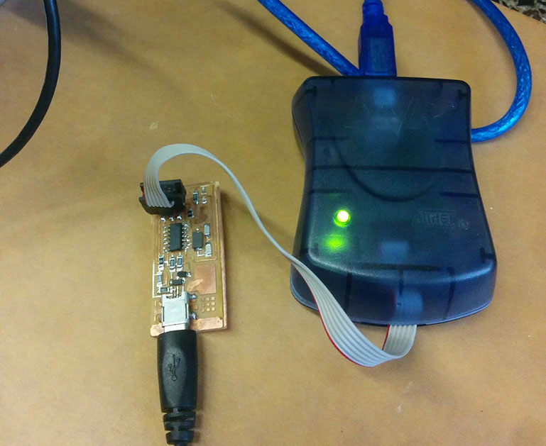
Testing the working of Fab-ISP
Connect ISP to the computer via Micro USB cable and one end to the AVR.
It is showing red light which denotes that ISP is not working due to the following problems:
- solder bridges while soldering
- problematic soldering of components
- overheating of elements while soldering
- failure of components due to overheating during soldering

Connecting other ISP to the AVR again and now it shows Green light which tells us that our circuit is working fine and now we can use it for programming other circuits
Following Video shows blinking orange light instead of red and green light, which shows that 6-pin header is inversely connected and you need to invert it and connect it again until it shows green light.