
Tapan
Betai

2016
Week-16 interface and application programming
Measuring Vibrations:
Procedure:
- Using Piezo sensor
- preparing the circuit
- coding
- uploading the code
- checking for digital output on the screen

Using Piezo sensor for measurement of vibrations
A piezoelectric sensor is a device that uses the piezoelectric effect, to measure changes in pressure, acceleration, temperature, strain, or force by converting them to an electrical charge.
Piezo sensors of different sizes
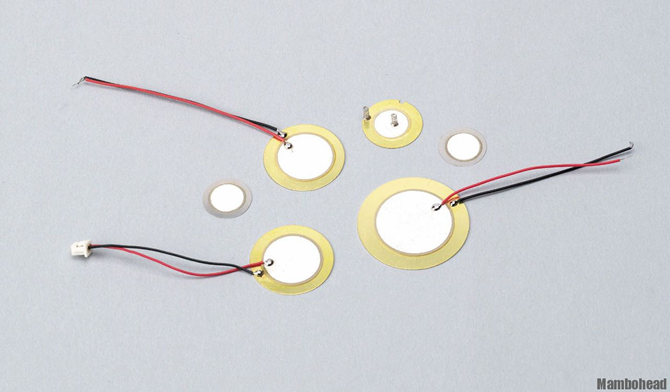
Preparing the sensor and circuit
Here logic behind this is simple. you can also use the logic of switch but here this sensor also shows intensity of vibration, which we are measuring.
It has only two connections, one goes to GND and other one goes to the one pin connected to the IC which gives signal.
Logic of Coding
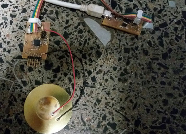
Consider following images for connections
Here we are using atmega 328 IC for programming that we made while embedded programming week.
One of sensor's end is connected to the GND and one end is connected to in connected PB0 pin of the IC which takes signal from the PIEZO sensor and sends to for the output on the screen. it has connected to the analog pin and delay of 2 millisecond is given to see the variation on the graph on monitor screen.
Coding: I found it difficult initially as it was about interfacing but when i checked online i got few things and tried them out.
Code file
Following image and video shows output of vibrations measured by the piezo sensor on the computer screen with the help of Graph. it shows variation in due to vibration that you can see in the video.
.jpg?crc=4122473574)
Final video of the output on screen via interfacing laptop screen and controller
Interfacing and application
I was Curious about this assignment, as i had choose my circuits of input and output devices accordingly.
Here in Fablab CEPT we have a huge heavy wooden door, people sometimes forget to close the door or they push it but it does not close properly, so i thought to make something to notify them.
But with time i thought to make a proper system for the same and i thought to welcome them in a Fab-way.
SO i made Array circuit in output device assignment.
Now here in this week i am connecting both the devices together for our usability at fablab.
Preparing switch circuit:
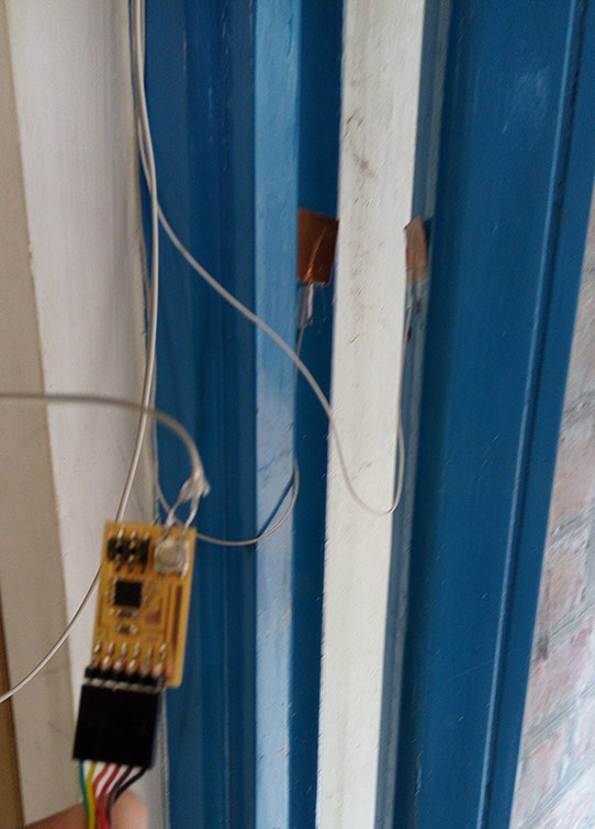
- As shown in the figure i have connected the button to the door via copper tape.
- I just needed something that tells circuit that it is closed, that is why i am using copper tape.
- I am not using the circuit directly by any means because door is very heavy and it can cause damage to the circuit if closed with more speed
- I have programmed the input circuit to read the opening and closing of the door
- circuit will send a signal to the output circuit when to start the led and when to shut them down.
- I have also checked the signals with analog output on arduino
Code for getting output form the input switch circuit:
//
//
// hello.button.45.c
//
// button hello-world
// 9600 baud FTDI interface
//
// Neil Gershenfeld
// 10/31/10
//
// (c) Massachusetts Institute of Technology 2010
// This work may be reproduced, modified, distributed,
// performed, and displayed for any purpose. Copyright is
// retained and must be preserved. The work is provided
// as is; no warranty is provided, and users accept all
// liability.
//
#include <avr/io.h>
#include <util/delay.h>
#define output(directions,pin) (directions |= pin) // set port direction for output
#define input(directions,pin) (directions &= (~pin)) // set port direction for input
#define set(port,pin) (port |= pin) // set port pin
#define clear(port,pin) (port &= (~pin)) // clear port pin
#define pin_test(pins,pin) (pins & pin) // test for port pin
#define bit_test(byte,bit) (byte & (1 << bit)) // test for bit set
#define bit_delay_time 102 // bit delay for 9600 with overhead
#define bit_delay() _delay_us(bit_delay_time) // RS232 bit delay
#define half_bit_delay() _delay_us(bit_delay_time/2) // RS232 half bit delay
#define input_port PORTB
#define input_direction DDRB
#define input_pin (1 << PB4)
#define input_pins PINB
#define serial_port PORTB
#define serial_direction DDRB
#define serial_pin_out (1 << PB2)
void put_char(volatile unsigned char *port, unsigned char pin, char txchar) {
//
// send character in txchar on port pin
// assumes line driver (inverts bits)
//
// start bit
//
clear(*port,pin);
bit_delay();
//
// unrolled loop to write data bits
//
if bit_test(txchar,0)
set(*port,pin);
else
clear(*port,pin);
bit_delay();
if bit_test(txchar,1)
set(*port,pin);
else
clear(*port,pin);
bit_delay();
if bit_test(txchar,2)
set(*port,pin);
else
clear(*port,pin);
bit_delay();
if bit_test(txchar,3)
set(*port,pin);
else
clear(*port,pin);
bit_delay();
if bit_test(txchar,4)
set(*port,pin);
else
clear(*port,pin);
bit_delay();
if bit_test(txchar,5)
set(*port,pin);
else
clear(*port,pin);
bit_delay();
if bit_test(txchar,6)
set(*port,pin);
else
clear(*port,pin);
bit_delay();
if bit_test(txchar,7)
set(*port,pin);
else
clear(*port,pin);
bit_delay();
//
// stop bit
//
set(*port,pin);
bit_delay();
//
// char delay
//
bit_delay();
}
int main(void) {
//
// main
//
// set clock divider to /1
//
CLKPR = (1 << CLKPCE);
CLKPR= (0 << CLKPS3) | (0 << CLKPS2) | (0 << CLKPS1) | (0 << CLKPS0);
//
// initialize pins
//
set(serial_port, serial_pin_out);
output(serial_direction, serial_pin_out);
set(input_port, input_pin); // turn on pull-up
input(input_direction, input_pin);
//
// main loop
//
while (1) {
//
// wait for button down
//
while (0 != pin_test(input_pins,input_pin))
;
digitalWrite(PB2, LOW);
//
// wait for button up
//
while (0 == pin_test(input_pins,input_pin))
;
digitalWrite(PB2, HIGH);
}
}
For more information about making this circuit go to week-11
Here using the same input circuit I have implemented the circuit into the door via copper tape connected to switch of the circuit.
Now After uploading the code via arduino as programmer, i had started output window in arduino which you can see in the video.
Connections with arduino are as per the program of arduino as ISP form arduino example library.
After doing this i wanted physical from the circuit, which tells us something and i then started combining both circuits that i made diring weeks of input and output assignments
combining them together is as follow.
Switch Circuit
Input Devices
Array Circuit
Output Devices
Preparing switch circuit:
- As shown in the figure i have connected the button to the door via copper tape.
- I just needed something that tells circuit that it is closed, that is why i am using copper tape.
- I am not using the circuit directly by any means because door is very heavy and it can cause damage to the circuit if closed with more speed
- I have programmed the input circuit to read the opening and closing of the door
- circuit will send a signal to the output circuit when to start the led and when to shut them down.
- I have also checked the signals with analog output on arduino
you can see the analog output of the circuit in the following image.
Here as shown in the video, we are giving power via arduino and testing whether it detects the closing and opening of the door or not.
You can dududududud \.......... signals in analog output screen of the arduino.
Dur to heavy vibrations it shows continuous series of dududududud......
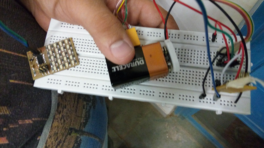
Now let's prepare output circuit
Lets connect them together with breadboard.
we needed breadboard for external power supply and for connecting the relay switch to give output according to input signal.
Here role of arduino is completed once we uploaded the code into the input circuit.
Consider the last video,
it works perfectly and measures input very accurately and it also works very fine with array circuit if opening and closing is very fast as shown in the video.