
Tapan
Betai

2016
Week-3 computer-controlled cutting
We are doing computer-controlled cutting this week on Vinyl cutter and laser cutting machines.
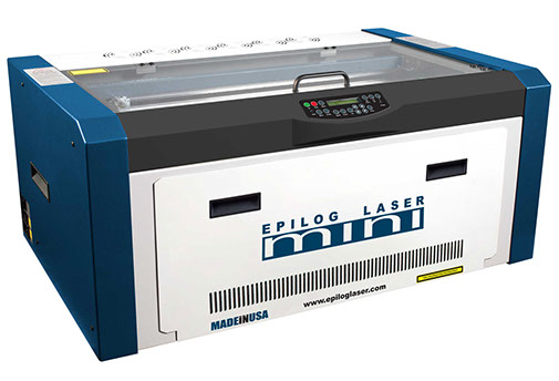
Laser cutting with Epilog mini 12*24
Materials:
following link will give you an idea of all the materials compatible in the machine
https://www.epiloglaser.com/products/legend-laser-series.htm
Specifications of Eplilog laser mini:
Engraving Area: 24*12
Power: 40 W
Maximum material thickness: 8"
Laser source: air-cooled CO2 laser tubes
Intelligent Memory Capacity: 64 MB
Resolution: User controlled from 75 to 1200 dpi
Print Interface: 10 Base-T Ethernet or USB Connection. Compatible with Windows® XP/Vista/7/8.
Electrical Requirements: Auto-switching power supply accommodates 110 to 240 volts, 50 or 60 Hz, single phase, 15 amp AC
Usability:
- Engraving
- Laser cutting
- Range of Material Can be used in the machine
- Markings
- Paper cutting, etc
Laser cutting
Step-1
Starting printing from cad software
Importing the file

Next image shows scalability of the design. you can cut any of the size in 2.5 mm thick sheet.
Here inside design also changes with the size and all other parameters changes with it.
Hear when we are scaling the design; all the parameter like length, height, width, area of the face, area of flower that we are cutting, grooves, etc are changes accordingly and the relation between all of them remains constant.
Volume is one of the parameter which changes in square proportion of the scaling factor.
Parametric drawing is shown in the following image.

Step-2
Here As shown, Preparing the file for cutting area and then going to laser printer settings by giving print command in Rhino.
After going to print window of the cutting you will have to select the region which you want to get printed by epilog mini.
Selected region shows the effective cutting window which will get cut.


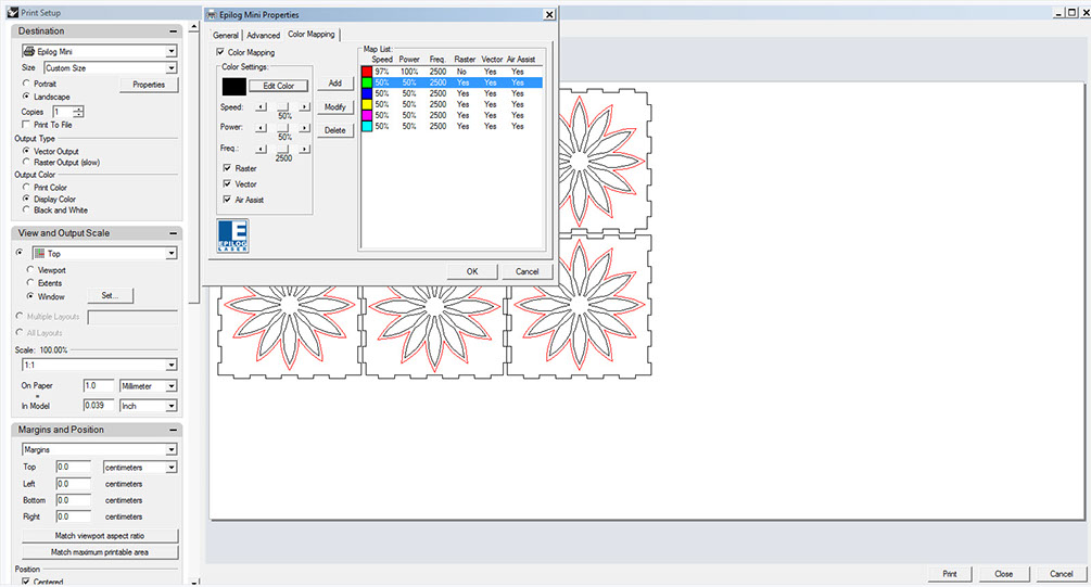
Step-3
Going to printer properties first and checking out the rastering, cutting and combined settings for different materials and different operations.

Step-4
Here as shown in the last image, we are doing two different operations which are indicated by two different colors.
Here Red color is for engraving and vector half cuts and black line vectors are for through cutting.

Step-5
After turning on the check box in color mapping tab, you can change add or minus the color for operations.
You can change properties for each and every color shown and can execute multiple operations with only one print command.
Step-6
Pressing OK button and then starting the printing operation.
Now go to the epilog mini screen.
you can see the name of the file has appeared on the screen.
you can start printing by pressing green button stating GO.

Step-6 Cutting process


Tolerance of 0.1 mm is given as laser burns that amount of material, and hence while fitting all the parts it stands without any adhesive due to that tolerance in the dimension of each press-fit
cutting properties
As you can see the picture there is property setting of epilog mini just like any other printer.
- you can change Options for vector, raster or combined from this window.
- After selecting the operation that you are doing you will have to change the speed, power and frequency
accordingly your operation on the material.
- For Mdf with 2.5 mm thickness i used speed of 9% and power 100% with frequency of 2500.
- With power 100% speed should be 13-15% for the same material but we are having some power issues with
the place and that is why the machine is not able to work on full power mode.
properties for rastering the image
- In the same window of the properties, there are other two tabs.
- If you are doing rastering then for advance options you can go to advance tab and you can select effect other than Basic.
- if you want to engrave a multicolor image on something, you first import the image, resize it and when you go to printing, in the machine's code it takes gray-scale for image and you can make machine identify as many possible gray colors by doing image in 3d rastering.
- There are six different effects for doing the 3d rastering and you can check it while doing it.
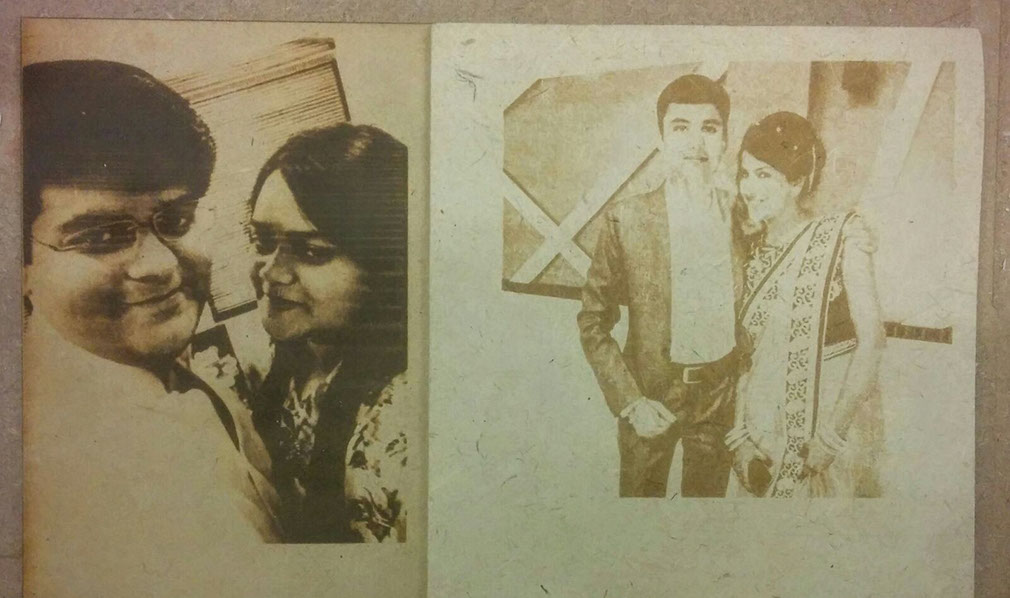
Laser Photo-Engraving with Epilog mini laser cutting machine.
It has been done by using 3d effect of rastering.
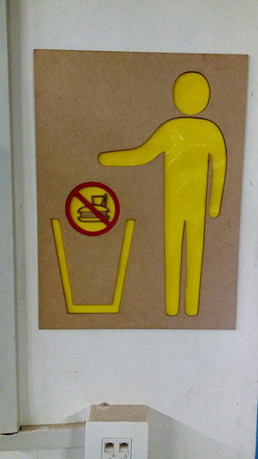
Color inlay process in Acrylic
Doing half cut in acrylic and then filling color in the half cut design.
Here the size of the workpiece is 4 feet* 6 feet on which i have done acrylic inlay process
Post processing after laser half cut
Filling duco paint(automobile paint) in half cuts.


Removing the protected brown paper after filling the color.
you can now see the pattern in which color has been filled.


Vinyl cutting with Roland Camm-1 servo

This machine comes with following specifications:
Cutting method Media: moving method
Loadable material width: 2 to 27-1/2 in. (50 to 700 mm)
Maximum cutting area Width: 22.9 in (584 mm)
Acceptable tool: Special blade for CAMM-1 series
Maximum cutting speed: 19.69 in/s (500 mm/s) (all directions)
Cutting speed .4 in to 19.69 in/s (10 to 500 mm/sec) (all directions)
Blade force: 30 - 350 gf
Mechanical resolution: 0.000492 in./step (0.0125 mm/step)
Software resolution: 0.000984 in./step (0.025 mm/step)
Distance accuracy(1): Error of less than ±0.2 % of distance traveled, or ±0.1 mm, whichever is greater
Power supply Dedicated AC adapter
Input: AC 100 to 240 V ±10 % 50/60 Hz 1.7 A
Output: DC 24 V, 2.8 A
Power consumption Approx. 30 W (including AC adapter)
Acoustic noise level during operation 70 dB (A) or less (according to ISO 7779)
Acoustic noise level during standby 40 dB (A) or less (according to ISO 7779)
Dimensions 33.9 in (W) × 12.56 (D) × 9.17 (H)
[860 (W) x 319 (D) x 235 (H) mm]
Weight 29.77 lbs. [13.5 kg]
Usability:
- Sticker printing
- Cutting of copper stickers to make circuits
- Paper cutting
- you can draw anything on paper by changing the tool with pen
- Paper cutting
- Signage
signages that we have made in our lab
Software specifications for vinyl cutter :
Cut Studio is the software that assist us in making anything on vinyl cutter.
It helps you convert image or drawing file into cutting format of vinyl cutter.
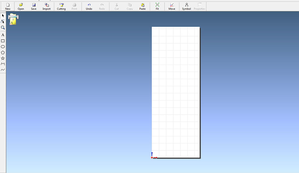
Let's Start the cutting
Opening the Roland Cut studio software
White area shows the cutting area according to the machine.
This software takes .jpg, .png, .dwg files as input.
This software cut the outlines hence it used only vector files.
If you want to cut anything from an image, you can import the image and you can make vectors in this software.
Importing an image and then right click on the image and go to option of image outline and one window appears on the screen, which shows your image and you can change outlines according to the colors and distortion in the image.

.jpg?crc=363376450)
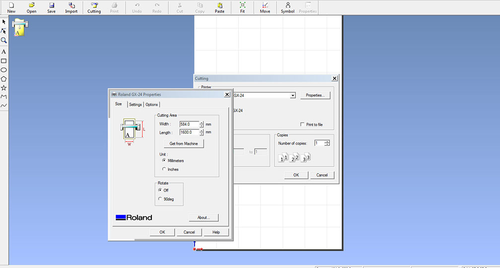
Now press cutting button on the top menu and again window appears on the window, click on properties in that window and another window appears as shown in the following image in which you can change the basic properties.
Now let's go to the machine and starting the machine and selecting the type of sheet that we are using and we have selected roll as we are using one.
You can choose piece if you are using a small piece and after selecting that option, machine will measure the length of the piece automatically.

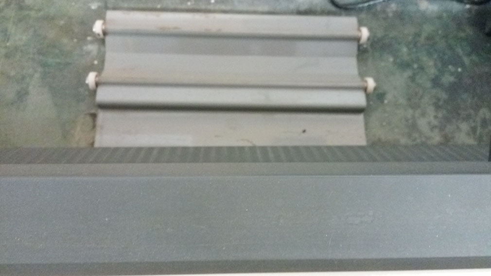
Now as shown in the next image you can see the differently shown part of the shaft with rough surface.
Which is used to give the exact size of

Provision to put the material roll
Mounting the material

For holding the material there is a lever.
with which you can align the material

Here in the following image i am testing the cutting force for the cutting.
Cutting force was set 210 gf for this material.


Cutting the test file for ensuring that whether it is cutting in the perfect manner or not.


Ready object after cutting
Generally we use cello-tape for taking out the cut part but here it is not so complicated and hence i am removing it by hand only.

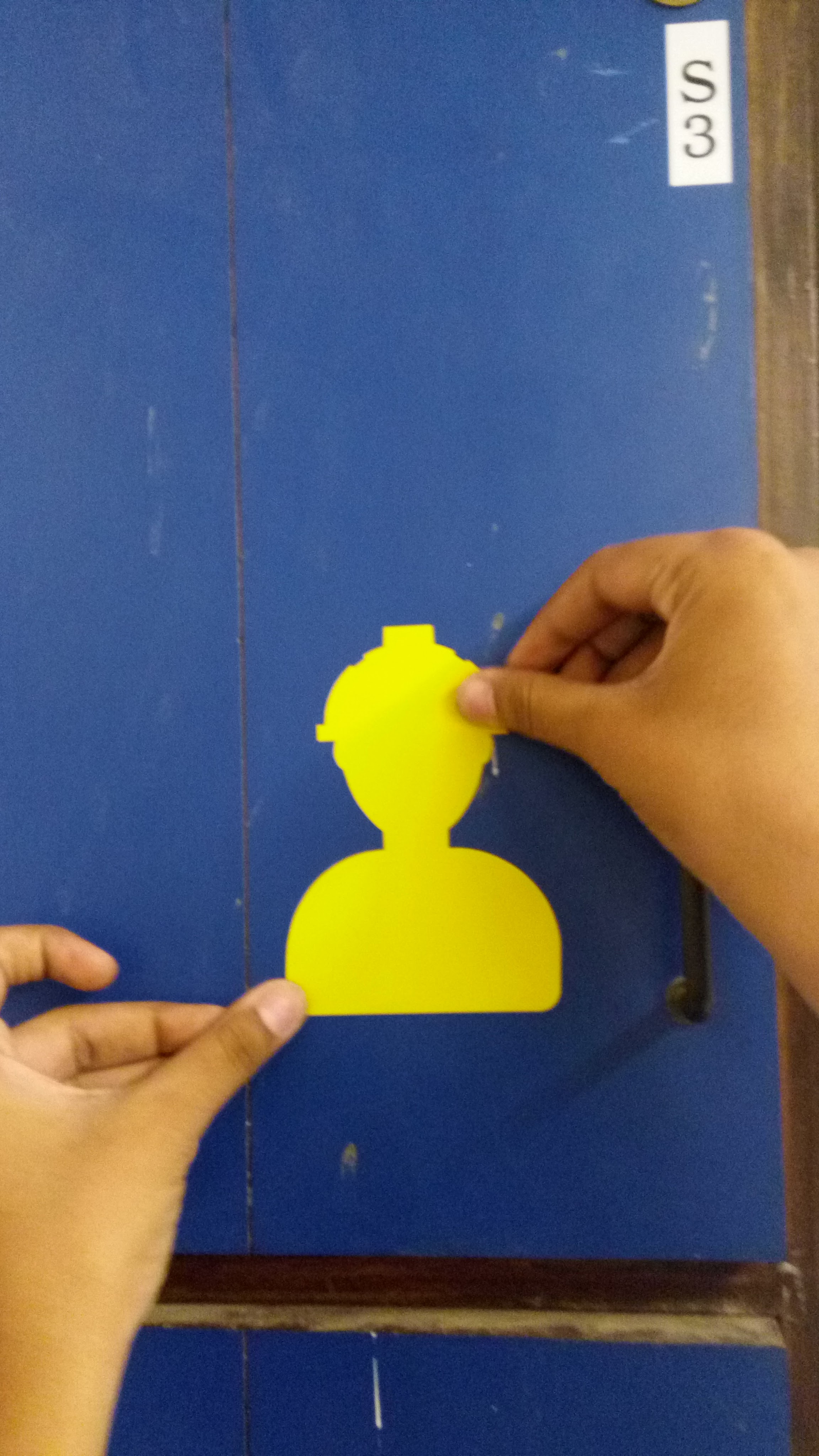
Sticking the object on my cup-board
