
Tapan
Betai

2016
week-13 Output devices
Array Circuit
another assignment with electronics, but now i am excited about it.
Today i am making an Array circuit.
I love lights, hence i have choose this circuit.
Flow of work for this week as follow:
- deciding the circuit i want
- milling the circuit
- soldering all the components
- checking the working of the circuit
- knowing about the method of working with the circuit as in this week assignment there is something different than usual coding
- I have learned about charlieplexing in this week assignment for running so many LEDs together in a sequence.
- I am also trying to write letters one after one.
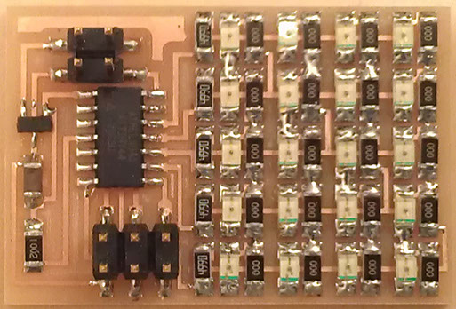
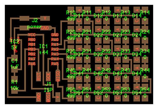
Circuit diagrams of Array output
All the components
Circuit board with the component name and values
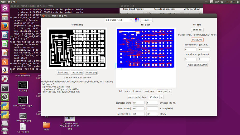
Tracing for milling with 1/64" bit
Cutting toolpath with 1/32" bit


Again starting with milling the circuit with fab-module software
- Settings for milling out a circuit is shown in the following image.
- blue lines shows the tool-path of the bit.
- it took 10.8 minutes for milling as shown in the image
Now consider the following image for cutting toolpath
Settings and parameters are shown in the image
It also shows the cutting tool-path

.jpg?crc=4030527080)

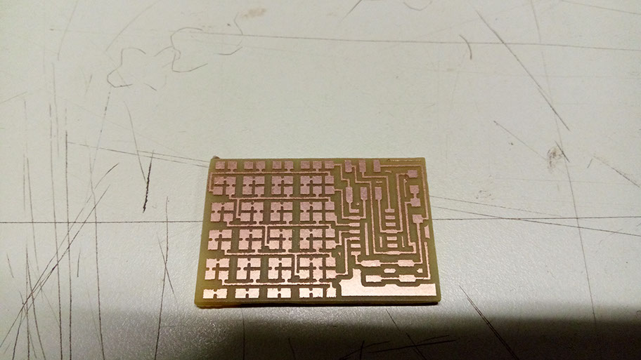
Consider following images for milling and cutting of the circuit that we are making
Consider following images for fresh circuit and then i started with soldering the components
As instructed earlier, attiny 44 is soldered first, then headers
and i have tinned all the connections for mounting the resistors and LEDs.

Consider following images for components
Circuit is ready for the use.
I have programmed the circuit with the arduino
in the same way i did with input circuit
you can find instruction for the same from week-11
-crop-u2343.jpg?crc=336916514)
As shown in the video
It works in the preset sequence when we gave power after programming
As shown in the video
Once circuit is programmed, it just needs power. i have now connected it with 3.3 volt button cell