
Tapan
Betai

2016
Week- 11 Input devices
Switch Circuit
I thought to monitor Any on/off or open/close device with just a switch because there are just two positions "on and off" but they can be used in any of the device for monitoring like in doors, fridges, for mapping of data in a space, etc.
Started miling the cicuit on Roland MDX-20 machine.
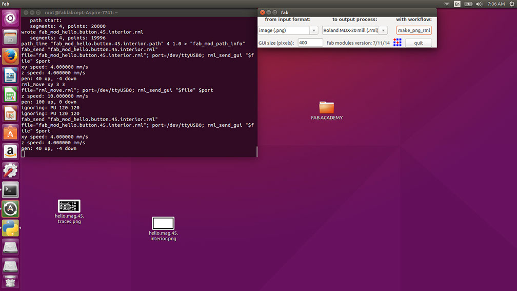
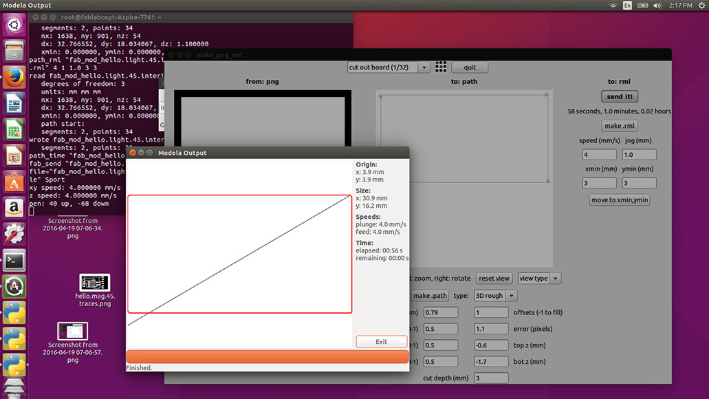
Step-1 Starting fab modules in linux
After starting Fab modules; select the process and the machine in the window and select the format of job.
In our case format is .png image.
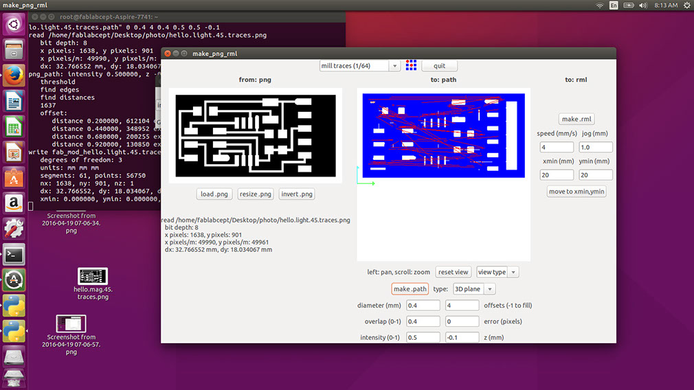
Step-2 Settings for circuit milling
- Load image from the left side of the window
(Dimensions and other aspects will appear in the bottom side of the loaded image)
- after loading the .png image select the operation that we are doing with machine and that is milling trace with bit of 1/64 inch.
- now in the middle bottom of the window there are certain settings appears and they contains pre defined values; for proper tracing, just change the value of error from 1.1 to 0 and change the value of overlap from 0.5 to 0.4.
- Press button make path and the window will show the path in central blank space.
- for tracing path, value of depth of cut is 0.1-0.15 mm.
Step-3 Setting machine for cutting
- fit the bit of 1/64 inch in the machine and mount the workpiece by double side tape on the bottom of it .
- now from the same window of the computer, move the bit from (0,0) to (3,3) or (5,5).
- and now lower the bit by button named "lower" on the machine and get it near the workpiece.
- manually set the z zero by lowering the bit.
and generate the rml file by pressing the make rml button.
Press the button send it
One more window will appear asking you to begin milling
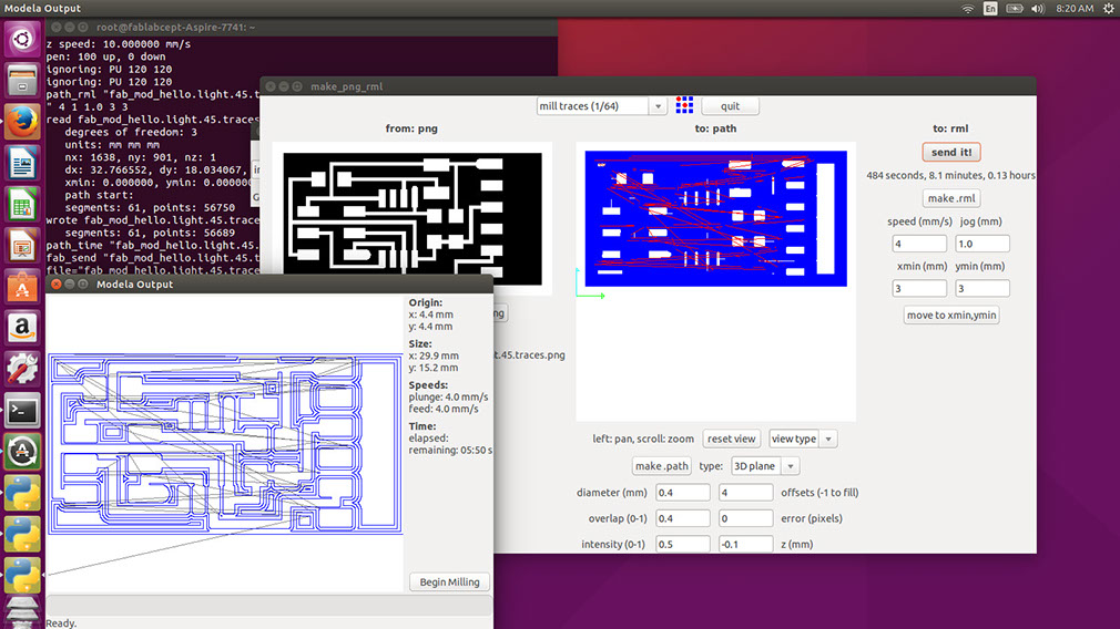
Press button Begin milling
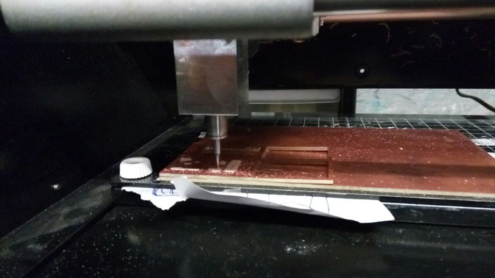
Paper is being fitted between the bed and plate for setting it in proper position.
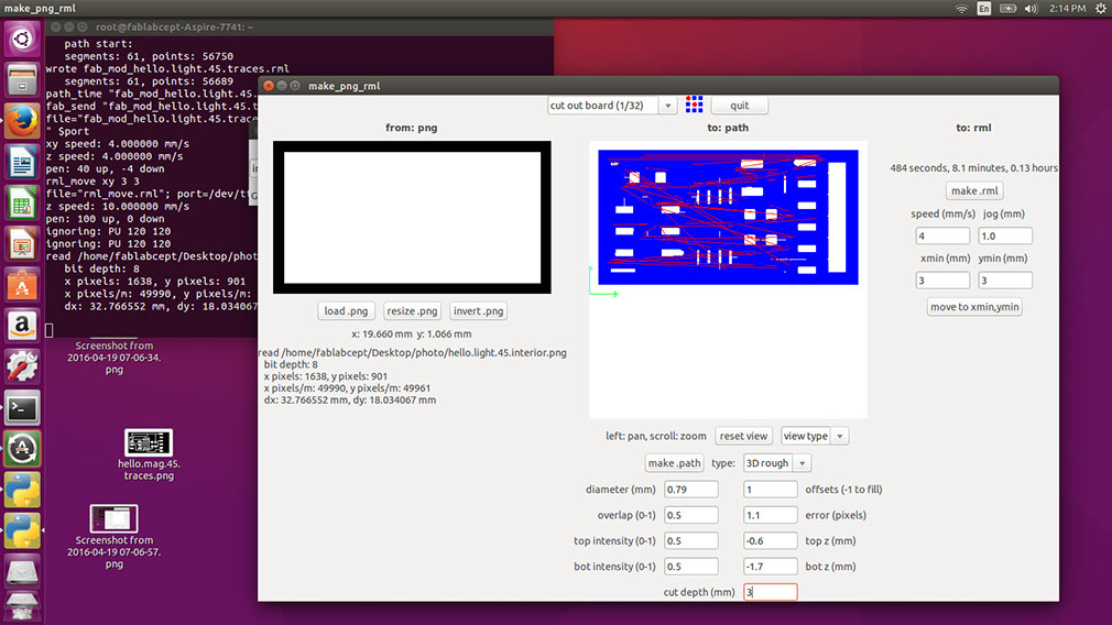
Step-4 cutting tool path
Load the image again in the same way and then change operation to tracing toolpath to cutting toolpath with bit 1/32 inch.
settings: just change the cut depth according to your material.
Ending window and screen
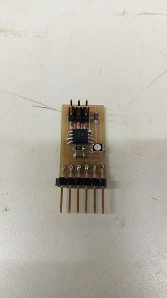
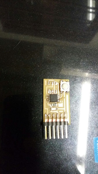
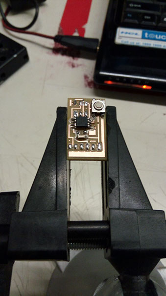
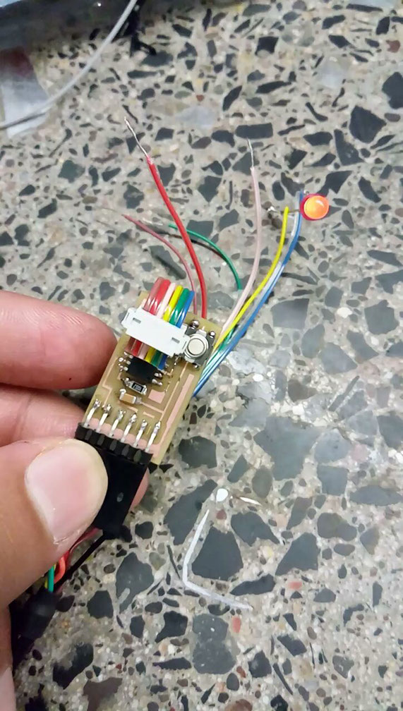
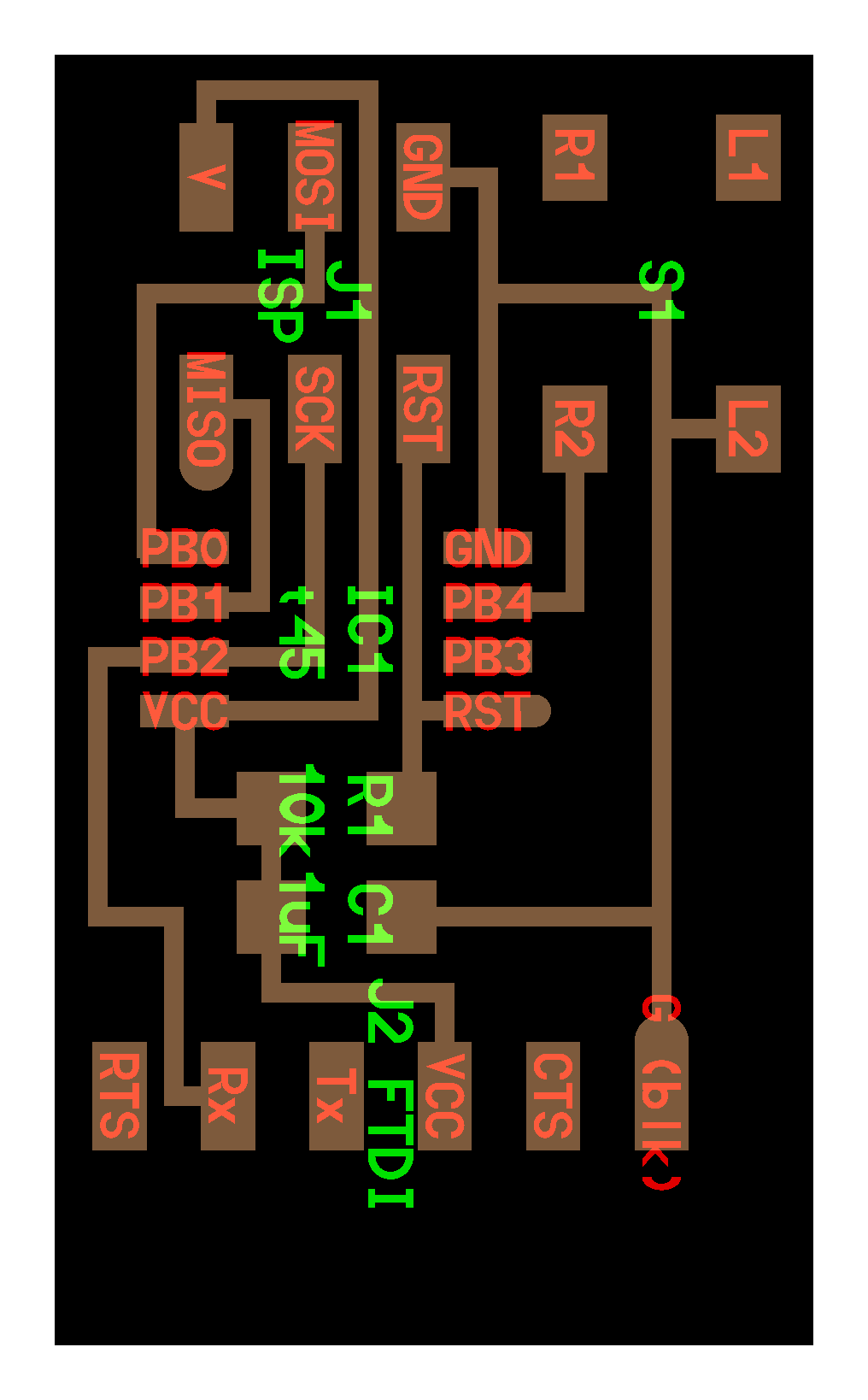
Soldering the Components:
1. Microcontroller attiny45
2. 10.k resistor 1 micro Faraday capacitor
3. 6-pin header
4. switch
5. 6-pin connector
6. LEDs
7. jumper wires
8. 6-pin header to usb connector
Programming Using Arduino UNO as programmer
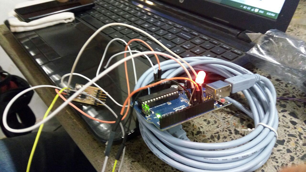
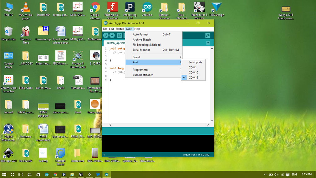
Changing settings for programming using arduino UNO as prograamer
Selecting COM9 in tools
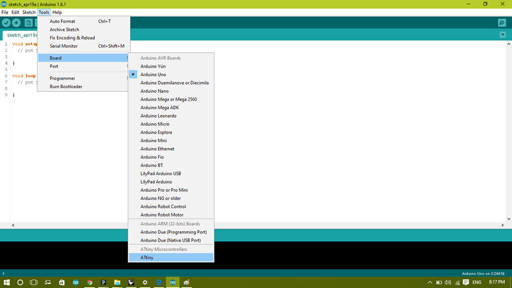
Selecting Arduino UNO from tools--board-- Arduino UNO
.jpg?crc=534699962)
Selecting Processor in tools as ATtiny45
After Writing the code it uploads program and we can play with our switch board.
Light blinks when switch is turned off for more than a certain time
Code
int buttonPin=4;
void setup() {
// put your setup code here, to run once:
pinMode(buttonPin, OUTPUT);
}
void loop() {
// put your main code here, to run repeatedly:
int val=digitalRead(buttonPin); //Reading the state of the button
if(val!=0) {
digitalWrite(1, HIGH);
}
else digitalWrite(1, LOW);
}
How the code works !!!
Normally in this type of circuit everyone tries to make something in which light turns on when we push the button, but here i am reversing the turning on and turning off operation of the circuit.
I defined this reverse working from my usability, i wanted to use this circuit with our fablab door because we had a problem of notifying people to close the door properly and for welcoming them.
so i made this circuit to take input of door opening and door closing.
Here in the following video you can see that switch is connected to copper tapes via wires which gives signal to the circuit.
So above stated code works to show door opening and door closing.
LED light ups when we leave button and when we press the button the light turns off.
Same type of mechanism is used in fridges to turn of and off the lights inside with door opening and door closing of the fridge, i took the same concept to work with our fablab door.
Take a look at the code, what i said has been put in code logic in repeatedly for infinite loops.
Now you just need to give power to the circuit and it will start it's work.
I have used the button circuit for measuring the door closing and opening
Here i have extended the length of the butting using wires and copper tape.
It is not so accurate due to vibrations of the door.
But it measures the opening and closing very accurately.
Refer the video
.png)