Assignment: Interface and Application Programming
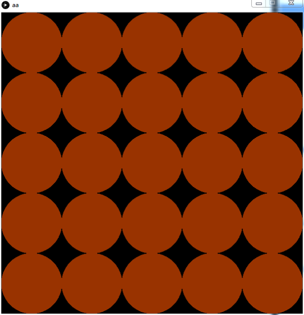
This project controlled LED Matrix by Processing. There are 5X5 circles displayed in the processing program screen. When you move your mouse over the circle, the color of the circle will change. When you click your mouse above the circle,the same postion LED in the Matrix will turn on or off. The interface of processing program displays below.
The communication between the LED Matrix and the processing is carried out through the serial port. To ensure successful communication, both baud rates must be the same, in this project, the baud rate is set to 9600.
Uploading program to Arduino first
In the Arduino program, the data received by Processing is passed through the Serial.read () function, and the data sent is the number corresponding to the LED light, from 0-24. In the program, set an array state[] to save the LED light's state , 0 - off, and 1 - on. When a LED number is sent to Arduino, the state value of the LED lamp is switched between 0 and 1. Then call the library function to light or extinguish the LED light according to the values in the state[] array.
You can download the Arduino program here.
Connection
Because I have no USB to TTL connector, so the project I use is Arduino UNO .
In the Processing program, the window size is first set to 600X600, and each circle has a
diameter of 120, so that there are 5 circles in the horizontal and vertical directions,
corresponding to 25 LED lights on the LED Marix.
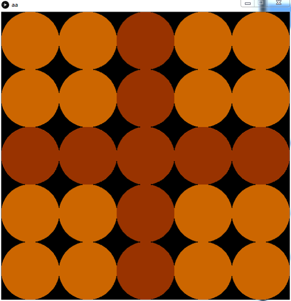
Then use the mousePressed () function and the mouseMoved () function to control the changes
in the state of the circle on the screen, similar to the program above, save the light information
in the array state[]. When the mouse clicks, the color of the light on the screen changes,
and the current LED number is sent to the Arduino through the serial port. When the Arduino
receives the number of the LED, it controls the on and off of the LED according to the status
information. Thus the synchronization of screen LED and LED Matrix is realized.
Open the program in the Processing. You can download the program here.
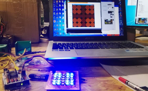
The effort of the project is shown in the following video. In the video, you can see when the mouse
click the circle in the computer, the state of LED will turn on or off.
Project effect
	import processing.serial.*;

	Serial myPort;

	int  [][] state;

	int x, y;
	color inside = color(204, 102, 0);
	color middle = color(204, 153, 0);
	color outside = color(153, 51, 0);


	void setup() {
	  size(600, 600);
	  noStroke();
	  background(0);

	  myPort=new Serial(this, Serial.list()[0], 9600);

	  state=new int[5][5];

	  float x=0;
	  float y=0;
	  for (int v=0; v<<5; v=v+1) {
		for (int h=0; h<<5; h=h+1) {
		  x=h*120+60;
		  y=v*120+60;

		  ellipse(x, y, 120, 120);
		  state[v][h]=0;
		}
	  }
	}

	void draw() {

	  for (int v=0; v<<5; v=v+1) {
		for (int h=0; h<<5; h=h+1) {
		  x=h*120+60;
		  y=v*120+60;

		  if (state[v][h]==0) {
			fill(outside);
			ellipse(x, y, 120, 120);
		  } else {
			fill(inside);
			ellipse(x, y, 120, 120);
		  }
		}
	  }
	}

	void mousePressed() {

	  x=mouseX/120;
	  y=mouseY/120;

	  println(y*5+x);
	  myPort.write(y*5+x);


	  if (state[y][x]==0) {
		state[y][x]=1;
	  } else {
		state[y][x]=0;
	  }
	}

	void mouseMoved() {
	  int x, y;
	  x=mouseX/120;
	  y=mouseY/120;

	  x=x*120+60;
	  y=y*120+60;
	  fill(middle);
	  ellipse(x, y, 120, 120);
	}