Step1: Material Guage Making
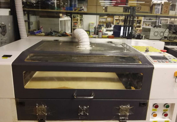
The following is the Laser Cutter of our FABLab Beijing. This machine can only recive the DXF file format. It can work on-line or off-line.
The brand of the Laser Cutter is HUITIAN LASER 4060, the software is LaserCAD, it is commercial, and provided with the Laser Cutter.
This assignment, we decide to use polywood as the raw material. Gauge testing is necessary to make sure the gap of each teeth. If the joints are loose, the model can't stand, if the joints are too tight, the model can't be joined together either.
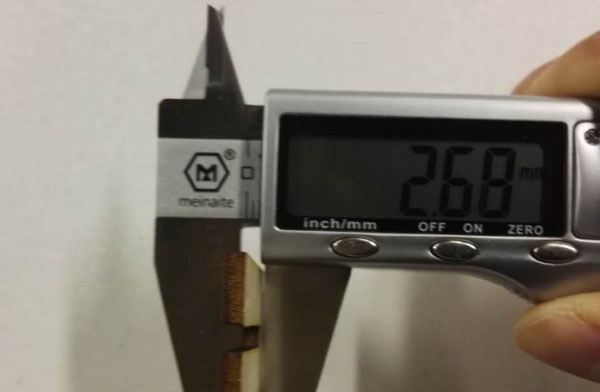
At first, measure the thickness of the polywood with a vernier caliper. The thickness is between 2.65mm to 2.7mm.
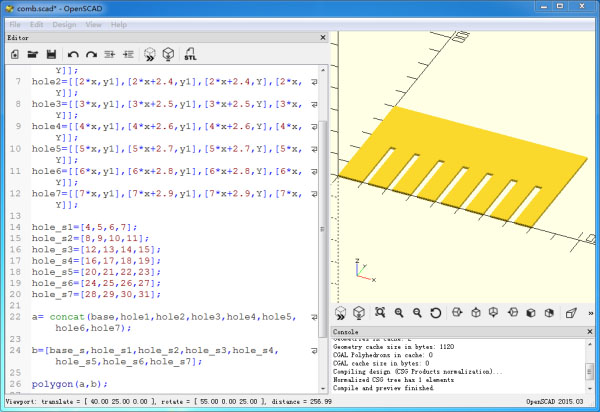
Use OpenSCAD to create a 2D shape with polygon function. You can download the OpenSCAD here. Then chick File menu,choose [File]->[Export]->[Export as DXF file ...] to export out as DXF file.
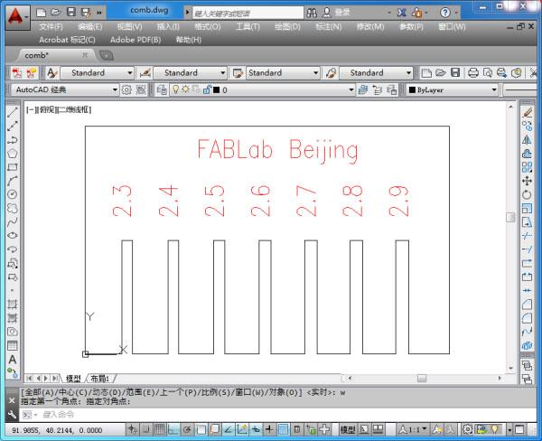
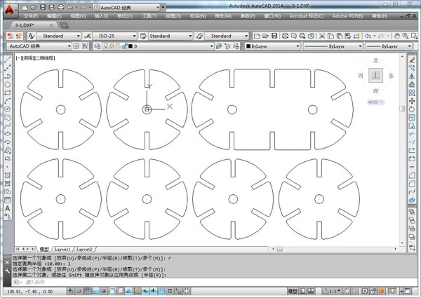
Open the above DXF file in AutoCAD, and check if the shape and dimensions are correct.
After checking, open the DXF file in the Laser Control software, set the cutter speed to 20,and the rate of power to 70. then save the export for the cutting file to USB disk.
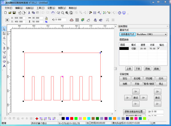
After checking, open the DXF file in the Laser Control software, set the cutter speed to 20,and the rate of power to 70. the export as a cutting file to USB disk.
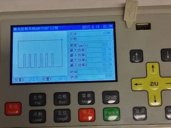
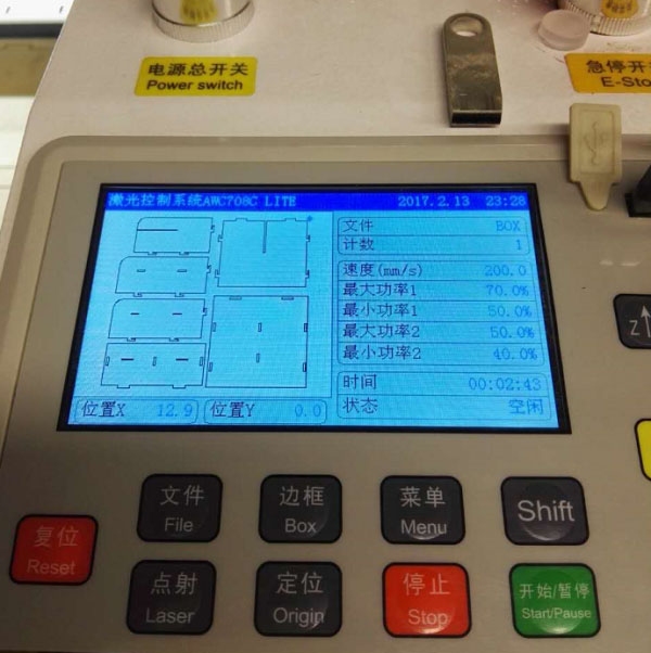
Plug the USB disk to the Laser Cutter. Setting the Origin point to the right position, click the Box button to test before cutting operation.
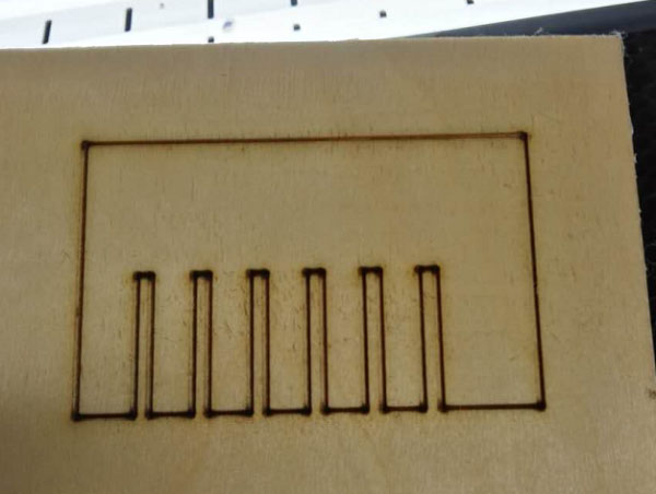
The first time, I made a mistake, the laser didn't focus accurately, the model was still conneted to the polywood after cutting.
Correcting the mistake, cutting two pieces sucessfully.
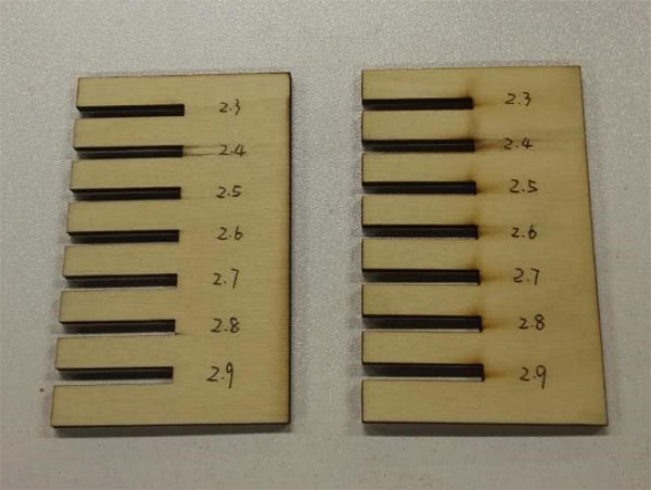
Jointing the two parts to test the gap. At last, I select the 2.4mm gap dimension which is suitable.
Step2: Box Designing
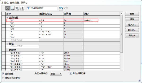
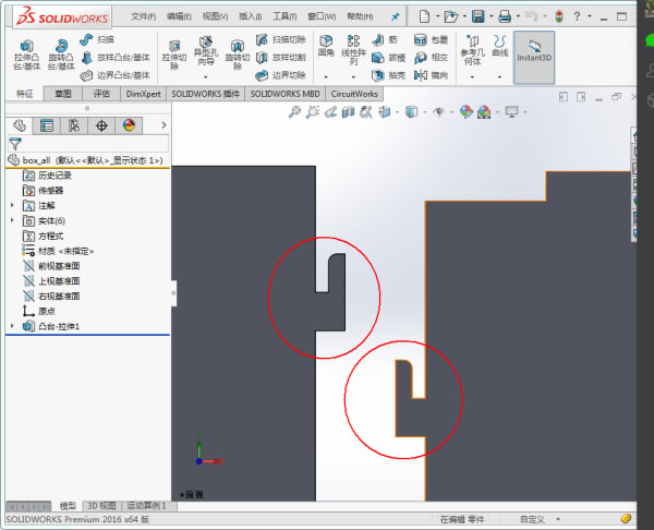
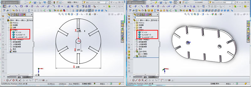
This time I want to make a wood box for placing electronic devices. I design the box by SolidWorks. In order to fit the different thickness of material, I set the parameter h1 to represent the thickness. When material changes, I should only change the value of the parameter,and the shape changes automatically. Designing completely export the design file to DXF formart.
In order to join two parts tightly,I fillet the insert corner with radius 1mm.
You can download the DXF file here.
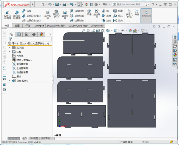
In accordance with the same operation above, importing the DXF file from Laser control software, and the export the off-line operating file.
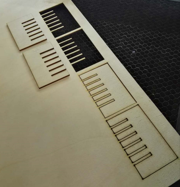
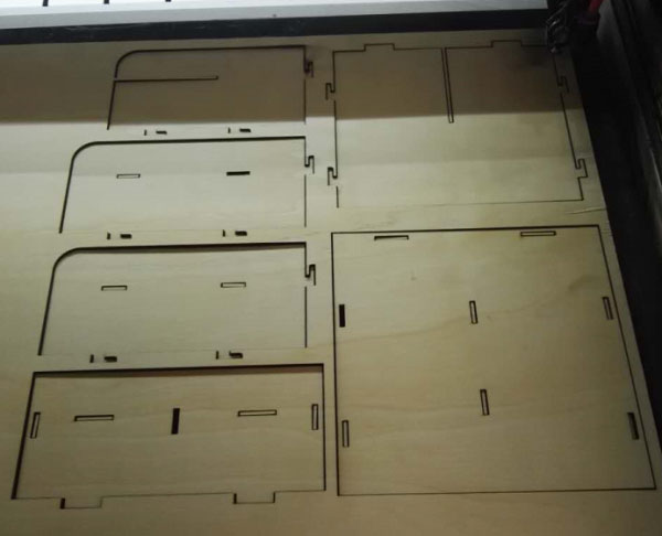
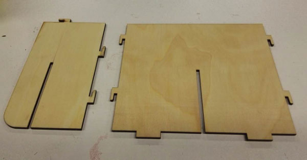
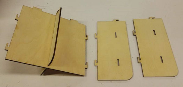
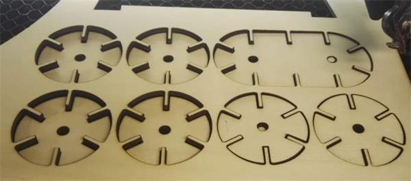
Here is the parts of my box.
Step3: Fabrication
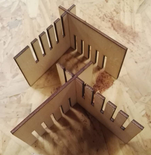
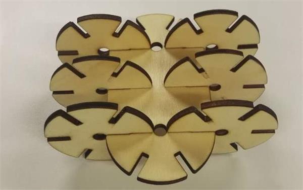
First, join the inner coressing two parts together. Attention: don't insert the horizontal piece to the right position, about 10mm space left.
Second , joined the two side pieces to the previous.
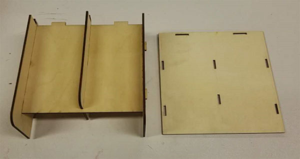
Then, join the bottom piece together.
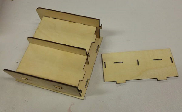
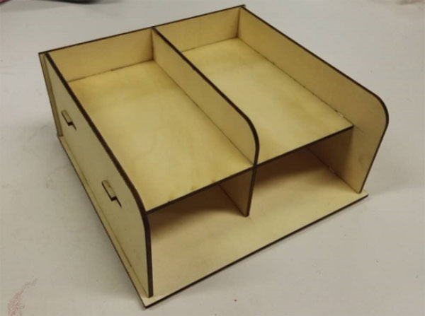
At last, connect the back piece to the right position. After all, pull the inner horizontal piece to its right posiition. So all the parts of the box were locked together.