Embedded programming
Assignment
- Read a microcontroller data sheet
- Program your board to do something, with as many different programming languages and programming environments as possible.
Data Sheet
The aim of this assignment is to program the board we designed in Week 6. It is a Hello World Board with an extra push button and a LED. First I needed to learn about the ATtiny44A microcontroller from the 286 page Data Sheet .
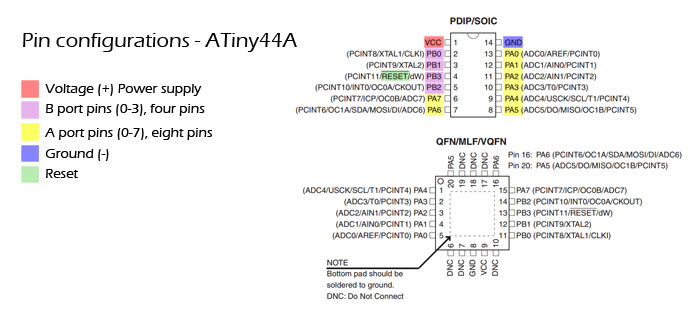
I found out in Pin configuration that each pin has a description of its functions. Some pins are A port pins and others are B port pins. We can only use one function of one pin at the time.
If you want to read and search in the Data Sheet the description of each function use (ctrl + F).
Pin 1 is VCC (+) The power from the power supply. Pin 14 is the ground (GND).
PB1 and PB0 pins are for a crystal, but they can also be used as regular pins if no crystal is needed.
Pin PB3 is also for Reset. Voltage over 0.9V it will NOT reset. Voltage under 0.2 will reset the microcontroller.
Programming the Hello Board
After learning about ATtiny44A I could start to program my Hello board, or at least try to do it. I was told to follow this tutorial from Fab Academy schedule page: Hello.ftdi.44.program
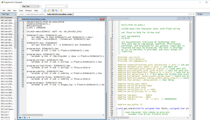
I went through the steps in the tutorial. I started to download the "hello.ftdi.44.echo.interrupt.c" and the "hello.ftdi.44.echo.interrupt.c.make" file from the Fab Academy home page. I saved the files in the Eagle folder on my computer: C:User_Name / eagle / My_hello_board / Programing files
I changed the "make file" by putting in the name of the "C file".
In Command Prompt I changed directory to the new folder and enter:
"make -f hello.ftdi.44.echo.interrupt.c.make".
When I did that "make" command I compiled the make file and created a hex file.
When executing the fuse- and the make command I found out that something was wrong, I did not get any response from my Hello Board. My instructor found out that I did not connect the six wire FabISP cable correctly to the Hello Board. I fixed that and tried again but the Hello Board still did not respond. Next move was to look at the schematics from Eagle to find out what was wrong.
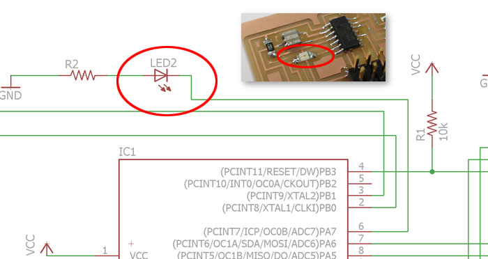
When looking at the schematic my instructor found out that I did not turn the led in the right direction regarding the ground and pin. I needed to unsolder the led and turn it 180 degrees.
Now I knew that my Hello Board was working but I still needed to play with the button and the led. I tried to do it in the "C" code but each time I tried something I hit a wall. After a few frustrating hours that did not lead me anywhere I decided to stop and try to program the Hello Board with Arduino Software.
Programming the Hello Word board with Arduino
Like I said above I was little lost because programing is totally new to me. First I read some pages from previous years in Fab Academy. I found a link to this great tutorial on Sigridur Helga Hauksdottir Fab Academy 2015 page; HighLowTec . This tutorial is for setting up the FabISP into the Arduino software. When I had finished the tutorial I was ready to set the sittings in Arduino.

I clicked on Tool/Board and clicked on "ATtiny". I was very happy when I saw that Arduino recognized my FabISP and I could set up further settings for the Arduino software.
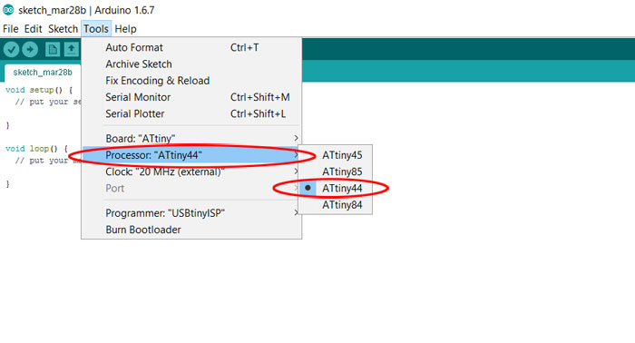
I needed to set up what Processor I was using in the Fab Isp and that was of course "ATtiny44".
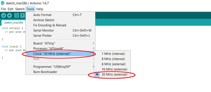
The external clock in FabISP is 20 MHz. If we don’t have "external" clock we need to pick "internal" clock or your microcontroller will stop working (until you connect an external clock to it). We don´t have to worry about that because we have external clock on the FabISP.
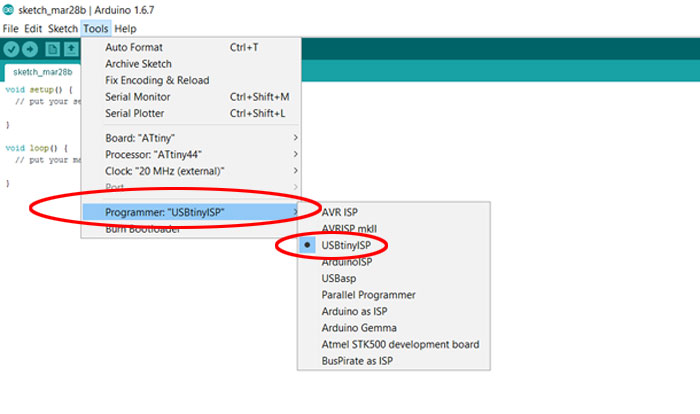
Finally I set the "Programmer" settings on "USBtinyISP". Now I was ready for programming the Hello Board with Arduino.
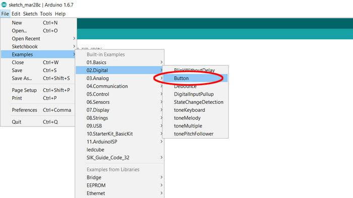
When you are a beginner like me it´s great to be able to find examples in Arduino to start from. I clicked on "Examples/02.Digital/Button". After that I saved the file and started to mesh with the code.
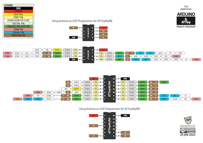
I found out quickly that the pins in the Arduino did not match the pins of the ATtiny44A microcontroller. I found a great chart on the Internet what solved that problem.
LED = Attiny pin: 6 (PA7) / Arduino Pin: 7
PUSH BUTTON = Attiny Pin: 10 (PA3) / Aduino Pin: 3
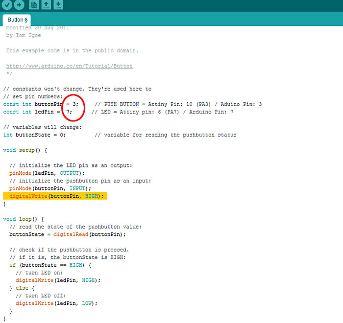
The function for this code is to make the Led light up and when the button is pressed the led will turn off. I needed to find the right pin numbers that is connected to the led and to the button from the microcontroller. To do that I used the chart above and wrote the right pin numbers into the code.
I added a line of code in the setup that activates the internal Pull-Up Resistor of the button pin; digitalWrite(buttonPin, HIGH);. After that I was ready to "Verify" the code and I did not get any errors. After that I sent the code into the microcontroller in the Hello World board and the led and button worked beautifully.
Led on-off from Vilhjalmur - Vimeo.
Now that I had done my first coding in Arduino I wanted to try another function, making the led blink slowly and then blink faster when the button is pushed down.
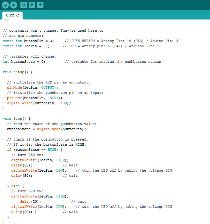
It was very easy to make this happen, few extra lines and finding the right delay time for the blinking of the led.
Blinking led from Vilhjalmur - Vimeo.