Networking and Communications
Assignment
- Design and build a wired &/or wireless network connecting at least two processors
For this week project my plan was to connect my LCD board from Output week and let it communicate with the Phototransistor board from Input week. But first I was going to learn more about networking and communications simply by milling out Neil´s Hello Bus board, program it and see how it works. This is essential for me because I have very little experience in programing.
Testing the Hello Bus Boards
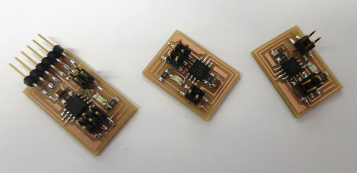
I did not take long time to get all the three boards ready. Because I was just learning, I did not change anything. I milled the boards and soldered the components. I did one mistake in the soldering and that was related to the LED´s. First I pointed the green stripe to the resistor but when I started to test the boards no LED´s worked. So later on in the process I turned the green stripe to the GND.
COMPONENTS:
- 3 ATtiny 45
- 3 Header 6 pins
- 3 Header 4 pins
- 3 Capacitor 1uf
- 3 Led
- 3 Resistor 1K
- 3 Resistor 10K
- 1 Header FTDI 6 pins (Only on bridge board)
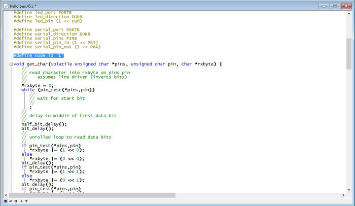
First thing to do was to download the hello.bus.45.c file and hello.bus.45.make file from the Fab Academy home page. I put the files in a folder and needed to edit the C code file for each board. Each node, in fact, needs a different node id number (see picture). So the hello.bus.45.c has to be downloaded and modified three times: one time to flash the bridge board, the second and third time to flash the node boards. Bridge board got the id 0, the node boards got the id 1 and 2.
After making the three C code files I opened a command window in each board: (Right click on folder and hold the shift button down/ select Command Window here).
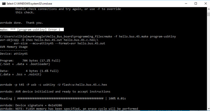
In the command window I wrote the command: make -f hello.bus.45.make and hit enter. I ran the: make -f hello.bus.45.make program-usbtiny-fuses command but that is not needed, there is nothing about fuses in the make file. Next thing to do was to connect the board to Fab ISP and program it with this command: make -f hello.bus.45.make program-usbtiny. I got an error message (see picture), I Googled the problem and it said: This response from avrdude means that it can talk to the programmer but the programmer can't talk to the chip. Ahh...I forgot to power the bridge board with FTDI cable. The USB cable from the FabISP does not power both boards. When I connected the FTDI cable the programing went smoothly for all of the boards.
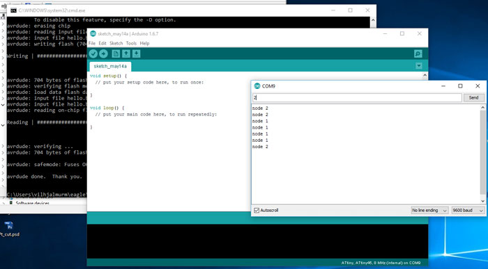
When I had programmed all the boards I opened Arduino IDE and went to Tools/Serial Monitor to open the Serial monitor. Into the serial port I entered the number of a node and sent it. After all the LEDs light up once, the board that corresponds to the number that is entered into the serial port will light up again. If that does not work make sure you have added the right serial port for the FTDI cable in Arduino: Tools/Port: In my case it was COM9. I also had to make sure I had the baud rate set to 9600; in the serial monitor.
The process worked and I know little bit more about the basic concept behind the set up and it´s working principles.
I found this great information about RS-323 serial connection on this
Fab Academy Student page:
"RS-232: The bit-serial information flow uses two data line, one for each data transfer direction (RxD, TXD). Since the microcontroller works parallel, the serial-parallel transformation is performed by a UARTs (Universal Asynchronous Receiver Transmitter).
Asynchronous means that there is no shared clock - instead, each node can send its full-dataset if the line is free. The synchronization starts then by receiving the first start-bit (triggered by the slope); the stop-bit has the inverse level of the starting bit. Therefore the receiver synchronizes itself within the mean of each data-bit (this requires that the bitrates from transmitter and receiver do not differentiate from each other too much)
Each transmitted word starts with a start-bit (equals to logic 0), and end with a least one stop-bit (logic 1) for at least 1.5 bit-lengths. The information is transmitted between the start and the stop-bit."
Analog Photoresistor board
I said in the beginning I was going to do some testing on the Hello Bus Board and then try to let two of my existing boards communicate together. The LCD board from Output week and Phototransistor board from The Input week. Yes I am going to do that but first I wanted to do more tests drawing up an analog photo resistor board that can help me understand what I need for my final project.
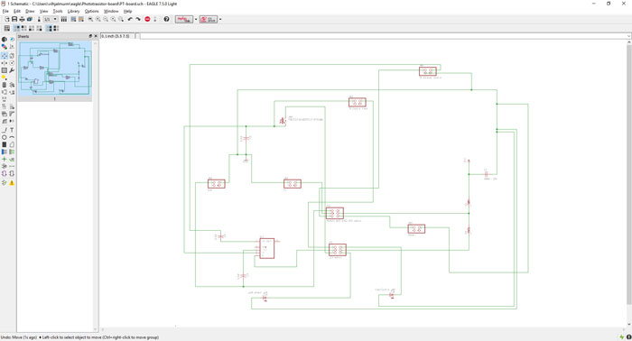
I did not have any schematic for this Analog board, but I got inspired by one circuit board bender, called Drew Blake. It´s an analog photo resistor sound board for electric guitars. The board is connected to buttons and analog controls to make all kinds of funky sounds from the phototransistor. For my final project I want to connect this board to my LCD board to get some function that I will explain later. But first I want to learn about this board and it´s Low Power Tone Decoder microcontroller (LMC 567cm). That microcontroller gives me the right output signal to the guitar output.
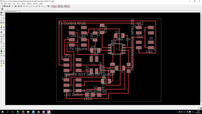
Most of the components for this board are not part of the standard Fab Lab inventory, there for I have to order them. I also don´t have the right foot print for the microcontroller because I don´t have it in my lab. When I will get it I will change the footprint. Like I said above this is just a test but if I am lucky I can let this board talk to the LCD board that I have already made, who knows!
Components:
- Low Power Tone Decoder microcontroller (LMC 567cm)
- (1) 4,7k ohms (1%) resistor
- (1) 33k ohms (1%) resistor
- (3) Ceramic Disc Capacitor 0.1Uf 104 DIP
- (2) 2x3 pin header
- (2) 2x3 pin header
- (5) 2x2 pin header
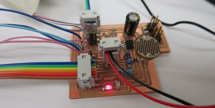
When I got all the components I soldered them to the board and connected all switches and potentiometers, plus a battery case. When I turned on the power switches the LED turned ON. When I turn on the Phototransistor switch the other led turned ON. Then I know this board worked, I only needed to plug it to the input and the output of a guitar for more testing. UNTILL THEN...
LCD board and Photo Transistor Board Communicating
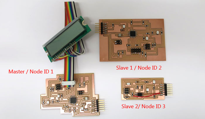
Because I made another LCD board in Output Week and the old LCD board was still functional, I could use that for this assignment. I decided to use the new board as Master, the old LCD board as Slave 1 and photo transistor board as slave 2. I was going to use Arduino IDE to program the boards and let them communicate to each other.
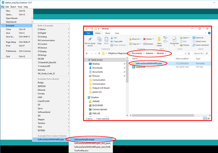
Before I started programming I needed to download a software serial library. I got this library from GIT Hub: SoftwareSerialWithHalfDuplex. After unzipping the document I needed to shorten the name of the folder: "SoftwareSerialWithHalfDuplex-master". Take the part "-master" away. The name of the folder should be: "SoftwareSerialWithHalfDuplex" I needed to put the downloaded folder in Documents/Arduino/libraries. When I had done that I could find the library in the Arduino IDE.
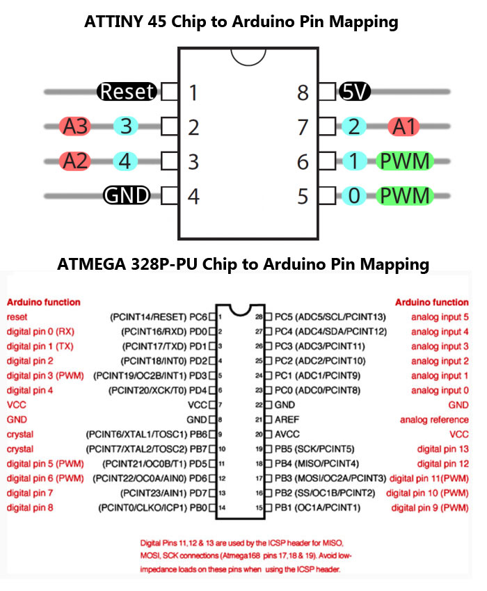
I also needed to know which pin I was going to use on the ATTiny 45 and ATMega 328 microcontrollers. Pin configuration for LCD screen and software serial, RX and TX. I needed to be careful because on Photo Transistor board some programming pins were shared with photo transistors so I did not want to select them.
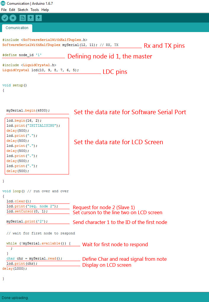
This Arduino sketch is for the master, the board that will be connected to the LCD screen and the FTDI cable. After installing the two libraries I could configure the pins. My instructor helped me with the code and to understand it´s function.
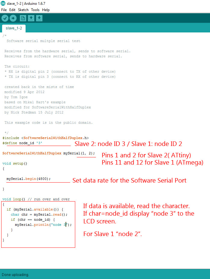
This Arduino sketch is for the two slaves. Slave 1 (NodeID 2) and Slave 2 (NodeID 3). I needed to change three things in the sketch from SLAVE 1 to SLAVE 2.
#define node_id '2' for Slave 1
#define node_id '3' for Slave 2
SoftwareSerialWithHalfDuplex mySerial(1, 2) for Slave 1
SoftwareSerialWithHalfDuplex mySerial(11, 12) for Save 2
mySerial.println("node 2") for Slave 1
mySerial.println("node 3") for Slave 2
And finally I also needed to define in Arduino IDE which microcontroller I was using for each board. Slave 1 using ATMega (Clock: 20 MHz external) Slave 2 using ATtiny (Clock: 8 MHz internal).
Connecting boards with Software Serial is quite complex process. I know I will have to dive much deeper into this method. I also need to work on my programming skills before I can do more tests. I will definitely use what I have learned here for my final project.
Final Project Networking
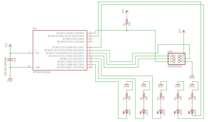
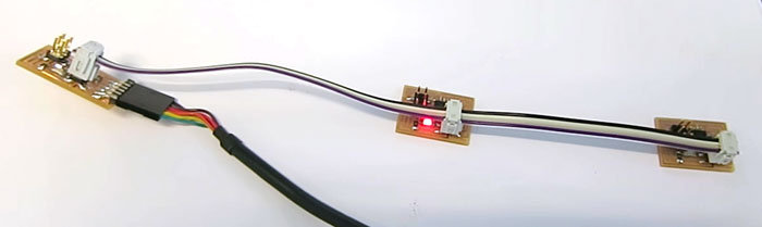
My final project needs a Led board that will be serial connected with the main baord or the digital board. The Led will tell which phototransistor in the neck is active. I choose ATtiny 44 to be the MCU for it and will use 2x3 pin connector to connect with the digital board.
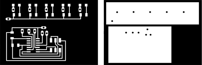
The Led board is in two pieces that are connected with wires. One ground wire and five VCC connection to each Led. On each connection is a hole that goes through the board that makes it more easy to solder and protects the end of the wire. I did not finish the drawing in Eagle I made big changes in Photoshop, especially on the cut file.
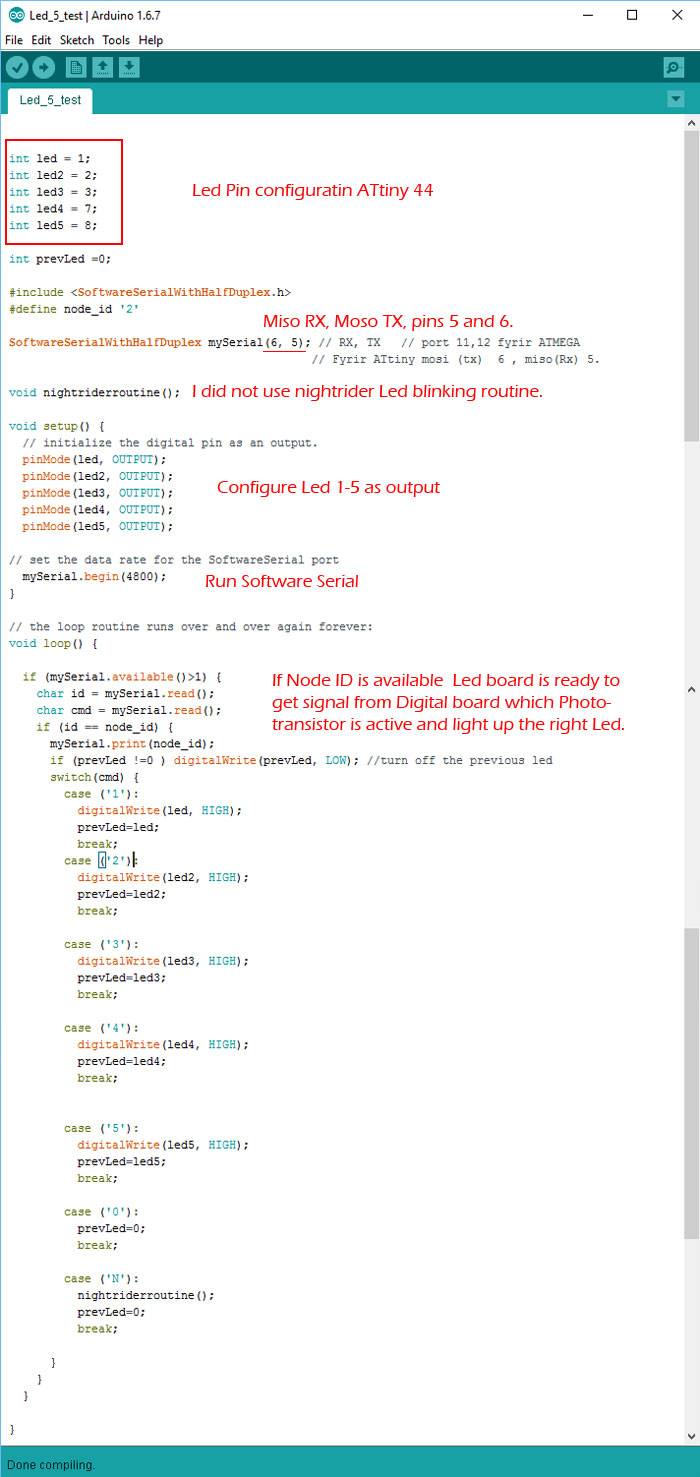
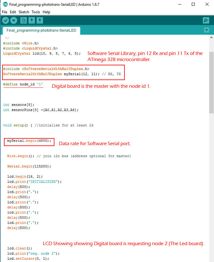
Like in previous code I needed to configure the pin I am using. Add SoftwareSerial to the mix and configure what pins are Rx and TX for communication with the digital board.
This is the function of the code for the Led board
Void Setup steps:
1) Set the data rate for the SoftwareSerial
2) Initialize the digital pins as an output for the Leds.
Void Loop steps:
1) Communicate with the digital board (Master) and light up Led that indicates the active phototransistor.
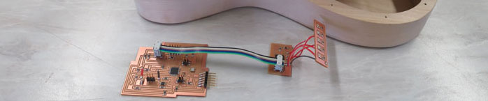
The small board is the Led board in two pieces connected with five red wire and on black wire. The other board is the digital board. The digital board will also be connected with LCD screen and to a analog board.
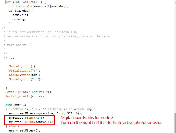
To connect a SofwarSerial I also needed to add command into the code for the digital board. Configure Rx and Tx pins and communicate with the node 2. I ran into trouble because the phototransistors was indicated from 0-4 but when the node 2 got the 0 value for photoresistor 1 it just turned off all Led when it was so post to light up active Led. Bas told me to add +1 to the (active) command, then it looked like this "mySerial.print(active+1); and the Led board did what it so post to do.
This is the function of the code for the digital board
Void Setup steps:
1) Set the data rate for the SoftwareSerial port and Wire Library
2) Initializing the LCD screen.
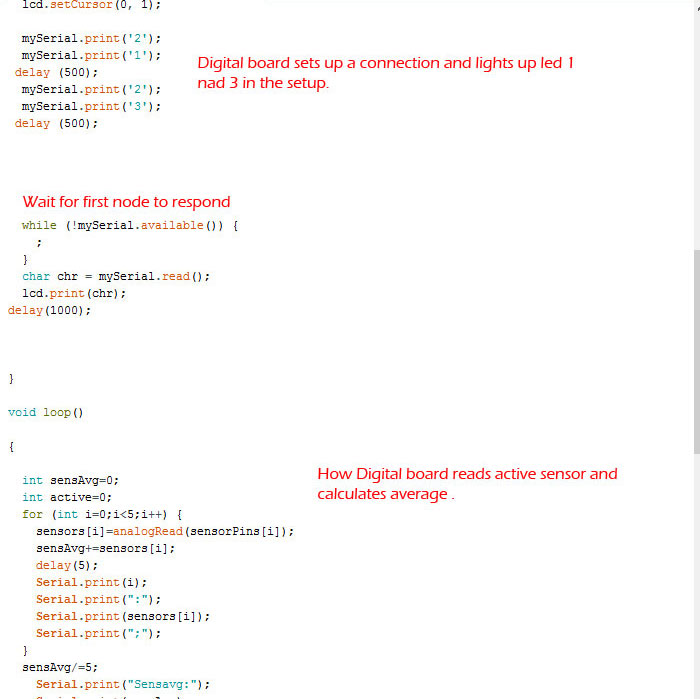
Void Loop steps:
1) Read phototransistors in the neck.
2) Calculate the average value of all phototransistors.
3) Send calculated value to the digital potentiometer based on the active transistor.
4) Tell the LCD screen which phototransistor is active and show its value.
5) Communicate with the Led board (Slave 2) and light up Led that indicates the active phototransistor.
Here is a short video showing the function, Led indicating the active phototransistor.