Assignment
- Documentation during development
demand- vs supplycomplete your final project, tracking your progress:
- What tasks have been completed, and what tasks remain?
- What has worked? what hasn't?
- What questions need to be resolved?
- What will happen when?
- What have you learned?
Drawing up the guitar
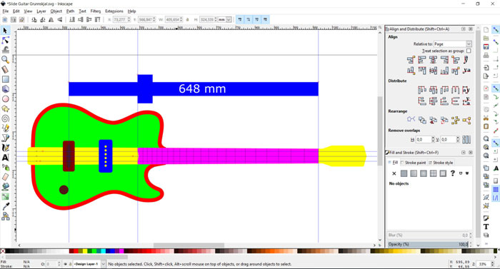
In Week 2 I drew up of the guitar, first in Inkscape 2D. The wood will be in three pieces, the neck that goes through the body, the body and a top plate.

I also drew up the guitar 3D in Week 2 . I used Rhinoseros
When I had made the neck I could not wait to mill out the bottom part of the body. Since the body was one side milling and no 3D needed I made the drawing in Inkscape.

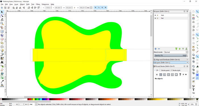
The top plate of the guitar was little complex to design. I needed to find out how I was going to fit the top plate to the bottom part of the body. Also fit all holes and wire paths. I made many tests in a cardboard before milling out the final version of the top plate.
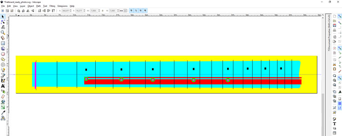
I drew up the fretboard in Inkscape and holes for the phototransistors. The plan was to mill it out in the Shop Bot and laser cut the fret slots in the laser.

Every electric guitar needs at least few buttons. I drew this button up in Fusion 360 and used Cura to export the file to our Ultimaker 3D printer. The three potentiometers I needed buttons for had different size of shaft so it took some time to get them to fit.
Parts that I needed to order
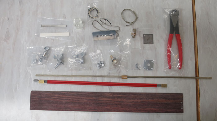
I ordered few parts from
StewMac for the guitar that I could not make myself; tuners, p-90 pick-up, wirers, pots, truss rod, rosewood finger plate, neck bone and fretting material plus some tools.
The neck and the body
In Week 7 I milled out the neck in the Shop Bot. The neck was milled from two sides both after 3D drawings and 2D lines. The picture is showing rough toolpath cutting in the milling process.

Here is the neck shaped out from a wood plank, ready for sanding and further processing. The Truss Rod was installed with some drilling. Everything was looking good. The rosewood fingerboard plate is lying beside the neck.
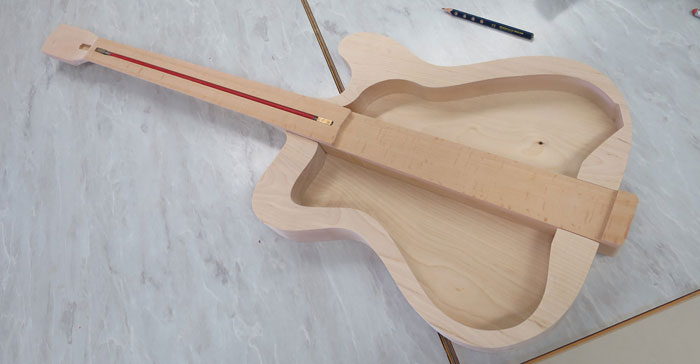
The milling went great, the Theremin Blues Slide Guitar was starting to get its shape. Now I could focus on the electronic parts and how to light up the Glass Slide.

I glued the neck to the lower part of the guitar body. First I was thinking to screw it stuck then I could mill out new neck or body if something happens to it but I decided to glue it. I made many versions of the top plate and laser cut it in cardboard for testing the fit. I also made a one test in 6mm thick plywood.
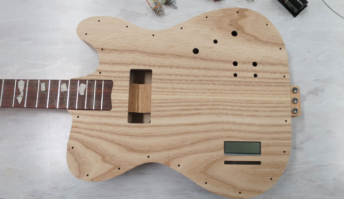
I milled the top plate in 7mm ash wood that I got from a friend who is a carpenter. I was very pleased with the look of that wood and now everything was coming together.
The fretboard

For the fret board I tested to laser cut the slots for the fret wire. It turned out beautifully. Because it´s a slide guitar the fret will not be rounded with sudden radius, therefore I don´t have to bend the fret wires before I install them.
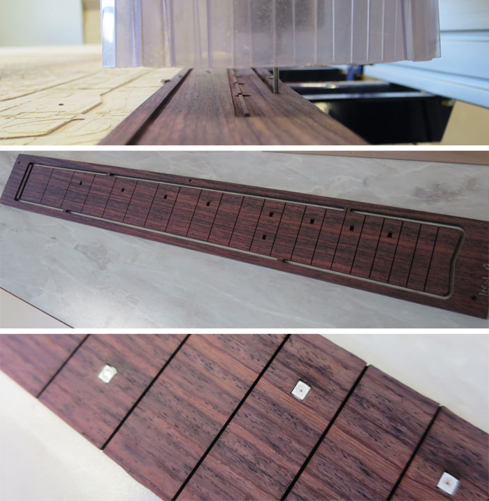
The making of the fret board was a good learning process and I am very happy with the outcome. On one side I milled out slots for wires and cut out the outline. Then I took the fret board and laser cut the holes for the photo transistors and the slots for the fret wires. Next move is to solder the wires for the photo transistors.
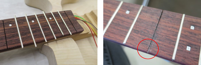
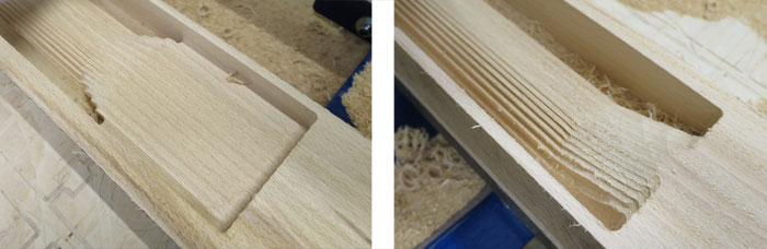
Fretting the fretboard was not an easy task, I had never done that before. There are many methods doing it, hammering it down, pressing it down with a special press, glue it and not glue it. I did not have access to fret press so hammer was my way to go. I fitted one fret without gluing it and it worked fine. The fret traces were not wide enough. The wire did not go smoothly into the traces I had hammered harder then I wanted. I was worried that I would damage the phototransistors in the neck or break the soldering.
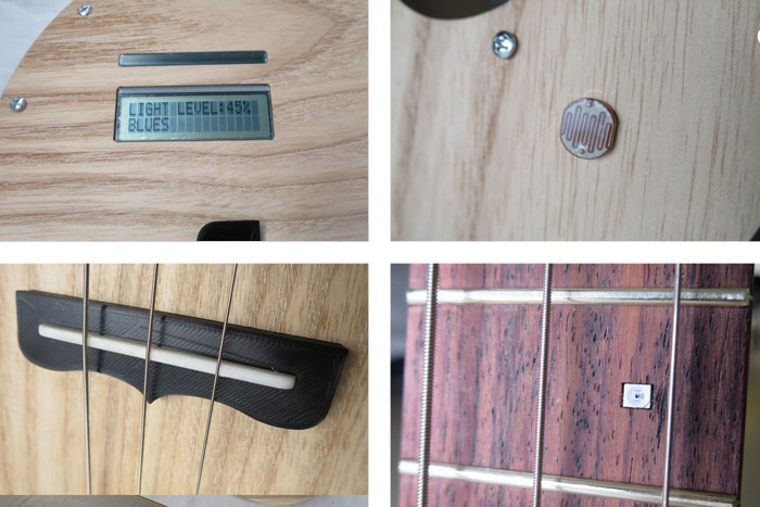
Then I ran into trouble on the 11th fret, it did not get stuck. I had to glue it down but the first attempt went bad and I had to take it off again. When I did that I chipped up the wood see picture. In the end I managed to glue the fret wire to the fretboard.
Immediately I tested the phototransistors and fortunately everything was ok.
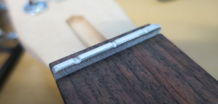
The nut bone is a crucial element of every guitar. For slide guitar it´s good to have it in metal. I choose aluminum, it´s hard but still easy to shape with sandpaper. The nut bone has to sit nice and tight into the slot, if not the guitar will not have good sustain and can be hard to keep in tune.
The Bridge

I put a lot of thought into what kind of bridge I should use for this guitar. Traditional Cigar box guitars have old key for a bridge or some metal object. I have an artificial bone from Stewmac that I wanted to test. I have always been fascinated by acoustic guitar bridges so I was going to try make one. I thought it would be cool to try to 3D print one and see how it works. I found a nice shape on the internet that I changed in Inkscape. Then I exported the vector images to DXF and opened it in Fusion 360. When I had finished the 3D in Fusion I exported the file as STL and opened it in Cura. I added 98% filling to it and printed it out in our Ultimaker.

The bridge looks good but how it works I have no idea. I look forward to test it out. Later in the process I changed the bridge because it was too big.
The electronics
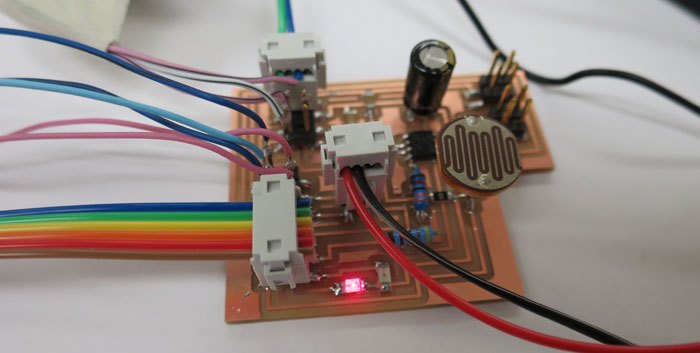
In Week 15 I worked on the analog board. The analog board controls the photo resistor located in the body of the guitar. The analog board gives the right signal to the guitar output.
When the analog phototransistor board was ready it was time to do some testing. It was important to get the analog part ready before I started to design the digital board. After the testing I realized I needed to order a digital potentiometer that would help me let the digital board talk to the analog board.
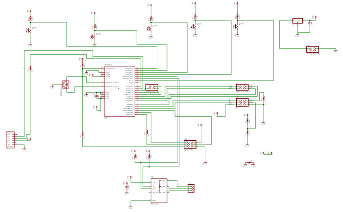
In Week 13 I made an output board with three phototransistors and the LCD screen. When I got a digital potentiometer I could finish the design of the final digital board based on the output board. I needed to add more phototransistors and make a footprint for the extra small digital potentiometer chip. That was a huge challenge.

After finishing the schematic in Eagle I took the PNG images to Photoshop and did some cleaning. I also changed some traces especially because the phototransistors are not going to be on the board, they are placed inside the neck. So I only needed five input and one ground for them. When everything was ready I milled and soldered the board without any problems.
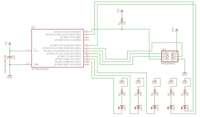
Documented in Week 15 the Led board.
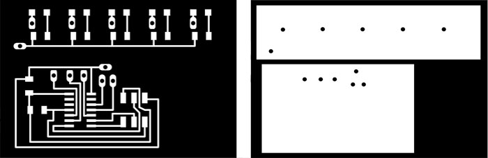
The traces and the cut PNG files for the Modela. You can see on the cut file that the Led board is in two parts so I could place the Led close to the small window that is mounted in the front plate of the guitar.
s
When I had finished the soldering of the digital board I made a led board that will be connected to the digital board. This led board will control five LEDs that will be placed in a light stripe above the screen. The LEDs will tell which phototransistor is active.

It was easy to wire up the photo transistors inside the neck. I was thinking to super glue the phototransistor to the wood but it was not needed. I did though hot glue the wiring because I want the soldering to be sturdy. When I have glued the fretboard to the neck I will not be able to access this wiring ever again.

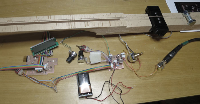
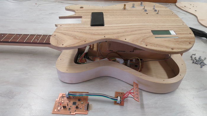
Before the presentation I decided to plug the guitar even though I had not finished the digital board and the programming for it. At that time I had not gotten one crucial component for my electronic setup and that is a digital potentiometer.
Video and answers for final presentation
- What tasks have been completed, and what tasks remain?
The instrument itself is 99% ready, just need to do some fine tunings and small things like the design of buttons and stuff. The 50% of the electronics is ready and most of the programming part is undone. I still need to finish the design of the digital board that controls the phototransistors in the neck. I will also need to design a small board that controls a RGB LED light, the light stripe above LCD screen, which will not take long time.
- What has worked? what hasn't?
The guitar works beautifully and the analog board works great. The 3D printed bridge looks good but it does not give well sustain. The design of the slide light is still too big and clunky. I did add two batteries in that thing and that’s making it to heavy.
- What questions need to be resolved?
Can I use the digital potentiometer that I ordered, it has very small footprint.
- What will happen when?
The rest of the Fab Academy time I will finish the design of the digital board and all the programming.
- What have you learned?
I answered this question in
Week 20.
Programming the guitar
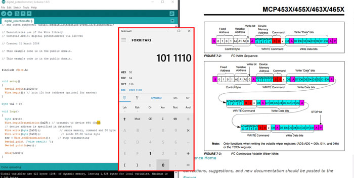
I was quite sure to use Arduino IDE to program the guitar. I had the code for the screen ready and I could read the phototransistors. What I needed to add was how I was going to communicate with the digital potentiometer. It’s not an easy task and I needed help from my Fab Lab instructor.
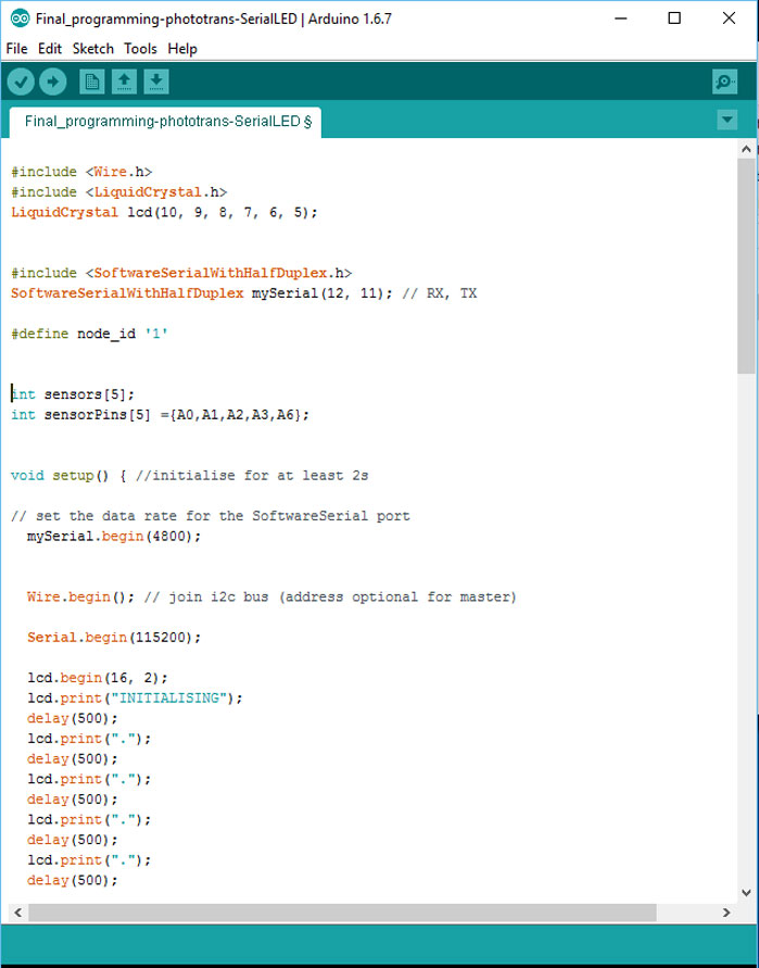
In this picture you can only see the beginning of the code for the digital board. You can see the whole code in documentation of Week 15 or download the Arduino file.
This is the function of the code for the digital board
Void Setup steps:
1) Set the data rate for the SoftwareSerial port and Wire Library
2) Initializing the LCD screen.
Void Loop steps:
1) Read phototransistors in the neck.
2) Calculate the average value of all phototransistors.
3) Send calculated value to the digital potentiometer based on the active transistor.
4) Tell the LCD screen which phototransistor is active and show its value.
5) Communicate with the Led board (Slave 2) and light up Led that indicates the active phototransistor.
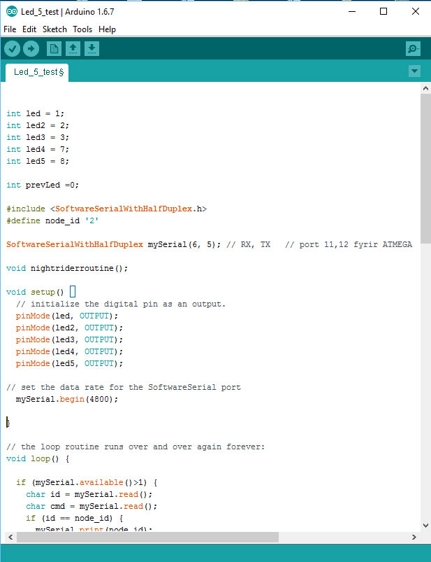
In this picture you can only see the beginning of the code for the Led board. You can see the whole code in documentation of Week 15 or download the Arduino file.
This is the function of the code for the Led board
Void Setup steps:
1) Set the data rate for the SoftwareSerial
2) Initialize the digital pins as an output for the Leds.
Void Loop steps:
1) Communicate with the digital board (Master) and light up Led that indicates the active phototransistor.
Drawing and 3D printing cover for the P90 pickup
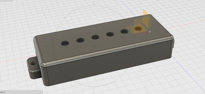
In Week 5 I worked on the cover of the P90 pick-up. I drew the cover in Fusion 360.
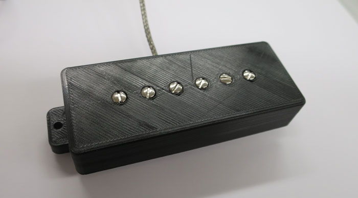
The pick-up needed to fit inside the cover and six screws sticking out on top. Later in the process I changed the cover. I did not want the coils screws to stick out of the plastic because the location of the strings did not mach. The instrument is a three string but the pickup is made for six string guitar.
The instrument
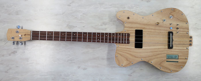
It was very rewarding to plug the guitar into my Orange guitar amp and hear its tone for the first time. Oh my God the sweet sounding blues tone. Of course I need to do some adjustments here and there but it´s so much fun to play with. In this first session with the guitar I played it for three hours, totally disconnected from the rest of the world.
There are many details that shape the look of the guitar. I wanted the guitar to have a technical geek kind of a look but also let the grains of the wood give it nice warm visual feeling. I could not be more happy with the look and the sound.
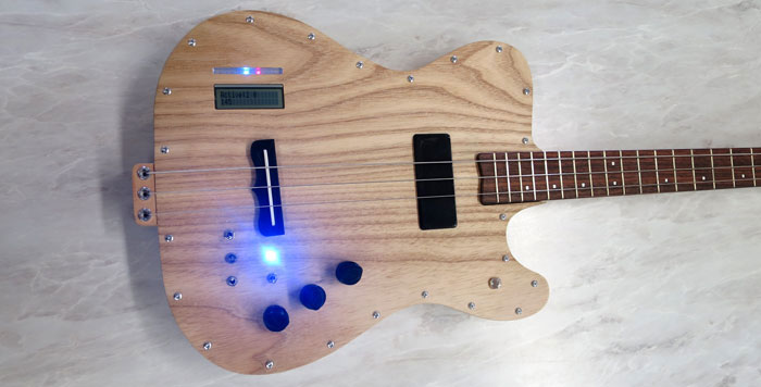
The Slide Theremin Guitar ready and all systems working ;-)
Final Project Files
Slide guitar Inkscape
Slide guitar Rhino
Guitar neck files
Guitar body files
Topplate files
Fretboard files
Pick-up cover file
Bridge files
Buttons files
Digital board files
Analog board files
Led board files
Programming files Arduino
Guitar slide light files
- ©vilhjalmurm(a)hornafjordur.is.
- Original template from: HTML5 UP