Interface And Application Programming
Assignment
- Write an application that interfaces with an input &/or output device that you made
- Comparing as many tool options as possible
This week topic is so interesting in so many ways. Unfortunately I spent way too much time on Networking & Communication so I had little less time than I wanted for this week. Hopefully I would find time to get some extra cool stuff up and running. After scooping around for something I found out that I wanted to test the software Processing 3 that seems to have some kind of Arduino flavor to it. I started to watch the 10 first videos of this tutorial series; Intro to Processing for Data Viz.
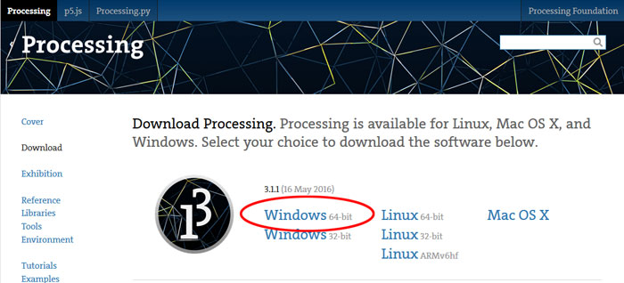
I downloaded a software from Processing.org , it´s a 64 bit version for my Windows 10 and it comes in a ZIP file, which I unzipped and located in my "Program Files Folder(x86)". I made a shortcut link to my desktop and I was ready for some experiments. I found a cool sketch with moving cubes from 2015 Fab Academy student . Unfortunately the student did only share the Processing 3 part but not the Arduino part. Since his video was high resolution I could write it down.

For this first test I was just going to get the sketch up and running. I found the pin configurations for Arduino (see week 15 if you need to find Arduino pin configuration for ATMega 328). The phototransistor was on pin 2. When that was ready I programmed the board with my FabISP.
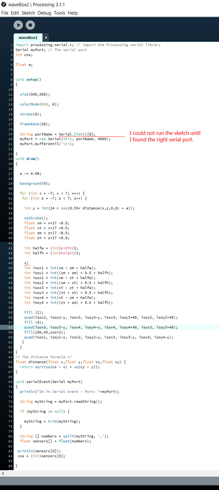
After downloading the code I opened it in the Process 3 software and tried to run it with my phototransistor board connected. I got an error message regarding the Port Serial. I needed to change this line: String portName = "/dev/tty.usbserial-FTG67J88";. To this line: String portName = Serial.list()[0];
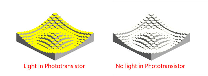
When everything was up and running and I put my hand over the connected phototransistor the color went from Yellow to White without any steps. To my disappointment no other colors appeared but that was just a challenge for me to find out how that works.
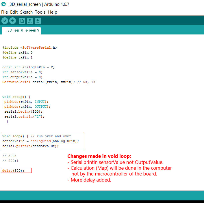
In the first Arduino sketch the sensor was sending value from 0 6. The microcontroller was mapping the value from 120 - 1024 to 0 -6. Since the computer is faster making the calculation I decided to send unchanged SensorValue not the calculated OutputValue to the Process 3 program.

To let the sensor change the color of the cubes by infecting the phototransistor signal I needed to change few things in the sketch. The name of the Int color was also a function so I needed to change that to Int col. Because I added more cubes in the sketch I needed to resize the display window with the moving cubes. I changed the color mode from RGB to HSB. Finally configured how the color mode reads the sensor value with the map function, reads calculated value from 0-100. Everything was ready for some color dancing cubes!
Related links
Processing Environment (IDE)Connecting Arduino to Processing
Processing Tutorals