Week 3 Computer-controlled cutting
Assignment
- Design, make, and document a parametric press-fit construction kit.
- Design a project for Vinyl cutter.
The assignment is to make a parametric press-fit design. I knew I wanted to model my 3D drawing out first and then make that model parametric. It is nice to see a 3D drawing made from a touch of a button as Parametric. But I am afraid to spend a lot more time building it that way, when I do not have much 3D parametric experience. In essence when I am creating 3D models I am drafting and that part is not a fast process. I have old speakers that has been laying around in the lab that I want to fit into a press fit box. I started to draw different shapes on piece of paper since I did not have any idea what I wanted. After few minutes I had sketched up a drawing of a robot head where the two woofers imitated eyes and so on.
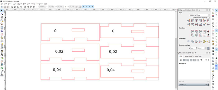
Neil had explained the importance of making a press fit tests with different offsets so I started drawing the tests in Inkscape. I needed to measure the material thickness but I was going to use MDF, the thickness turned out to be 4.1 mm. I thought it would be a good idea to do offset from 0 to 0.04 for me to see and feel the difference when fitted. I cut-out the forms with our laser cutter. After fitting those three different fits none of them had any resistance when I placed them together. Then I needed to raise the offset and cut out two more with 0.05 and 0.06 mm offset.
Lasercutter settings (Epilog Laser Mini 40W):
Speed: 10
Power: 100
Frequency: 800
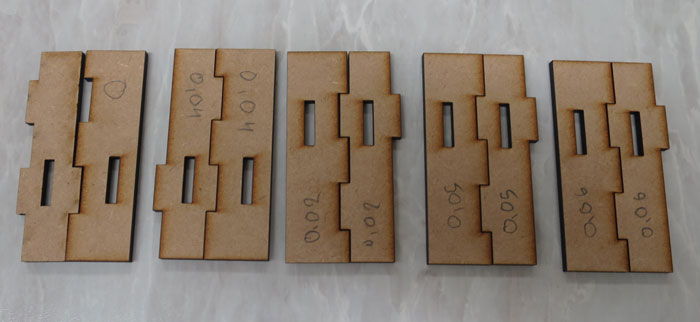
In this picture you can see the MDF test pieces. Because the first three fits did not have any resistance I cut-out two more with a 0.05 and 0.06 mm offset. I got quite good resistance with 0.06 mm offset but after fitting it and unfitting it many times it got little loose. So I decided to use 0.07 mm offset for my final outcome. I will explain more about how I worked with offsets later in this session.
Speaker Robot Head / Pressfit
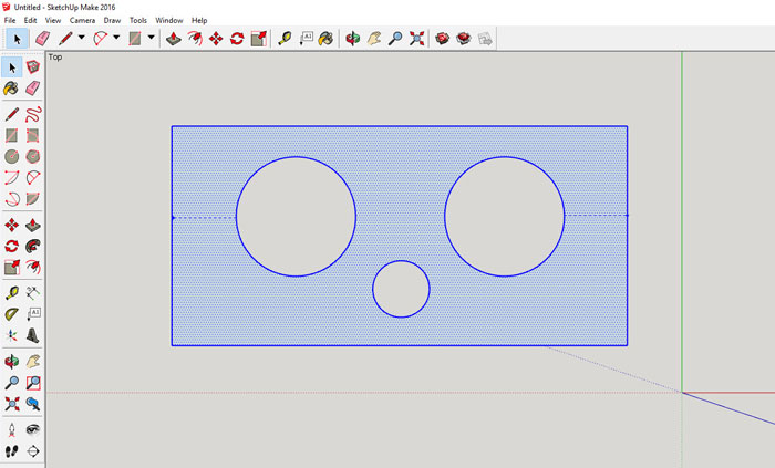
In this first attempt to make press fit design I used Google Sketch-Up. I started to draw up the front panel where the speakers will be fitted in. The size of the speakers will indicate the size of the front panel so it turned out to be 360x180mm.
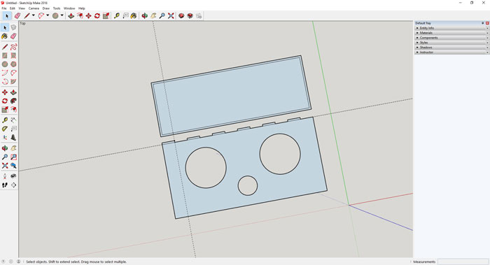
I started to work on the top panel and also to make the finger joints. Like I said above I wanted to design the box first before I started to think about making it parametric.
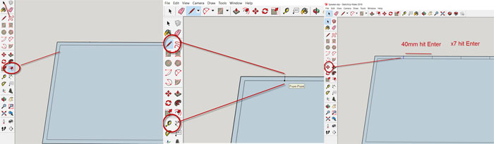
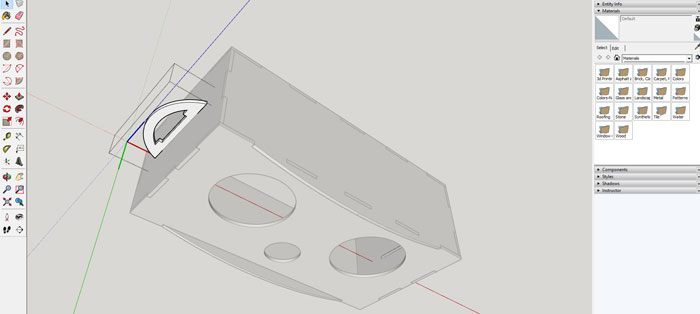
I drew up the finger joint quickly by first using the "Offset tool"(see first picture) and measure a guide line that is 40 mm from the corner with the "Measure tool" and draw the first line with the "Line Pen". Then I could use the "Copy/Move tool" to multiply the small lines hitting X and (number of copied lines) and hit enter.
I wanted to cut out a test in a cardboard but to be able to do that I needed to save the Sketch-up file as an older version of Sketch-up (2014). Then I opened the Sketch-up file in the
So I kept on drawing the box and added 4,1 mm thickness to the sides and worked on the top and bottom panel. I made each side to be individual component by clicking on "Make Component" bottom right next to the black selection arrow in the Large Tool Set bar. When each side was a component there was no problem to separate them from other sides, if needed, very important when using Sketch-up. Also when imported into V-CarvePro each side appears as a single component, flat and ready for the laser cutter.
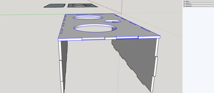
Next part was to work on the right and left sides of the box and I wanted to make a press fit handles that would imitate ears of the robot head. I thought the box was way to plane and I also needed some kind of protection for the speakers. So I started to draw up curved shape on the top and the bottom panel. This curved shape you can see on the next picture below will protect the speakers from bigger objects.
After drawing up the handles I placed them on both sides. I needed to make holes in both sides for the handles to snap into.
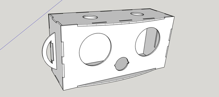
I made a little adjustment on the hole for the tweeter so the tweeter could be fitted in. Below you can find the Google Sketch-Up file.
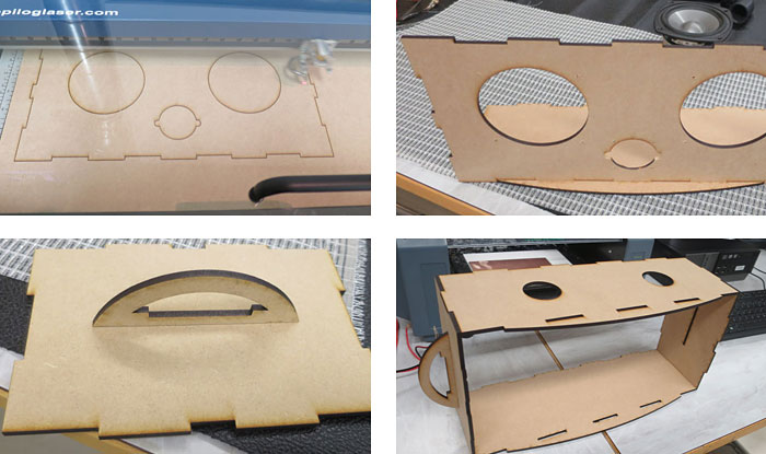
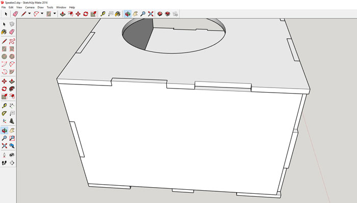
On the upper picture to the left the Epilog 40 watt laser was working on the first shape. The handles fitted nicely into the holes of each side. No need for any glue what so ever. It was difficult to fit the front panel into the bottom panel holes. It was tight but when it snapped it was a good press fit. On the bottom picture to the right you can see the box was starting to come together. The holes on the top panels were made for plastic air tubes that will stick out of the robotic head.
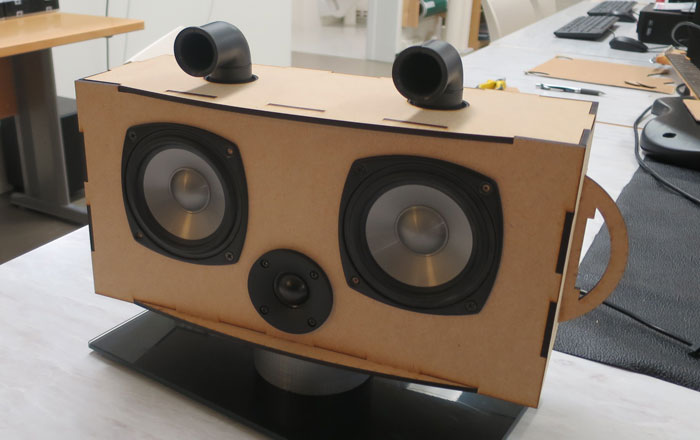
Here is the final outcome with the speakers mounted in and the air tubes on the top panel. I have a quite big subwoofer that I want to attach the head on to. It would be fun to take this project to another level, make a music robot or something. Maybe add a motion sensor and motor for the rotation of the head. Also program it so it can communicate with people that come into the lab. "Hello can I assist you? Do you need help"
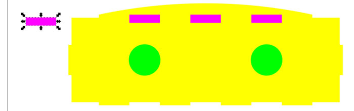
Parametric drawing of the robot head
Since I was too stubborn to start drawing the 3D picture parametrical I needed to find out how I was going to full fill that demand. First move was to save the Sketch-Up file as a Sketch-Up 2014 document and import it into VCarvePro like I did in an earlier state of the 3D modeling.
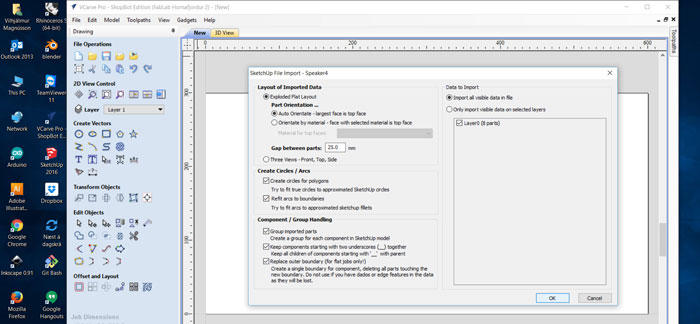
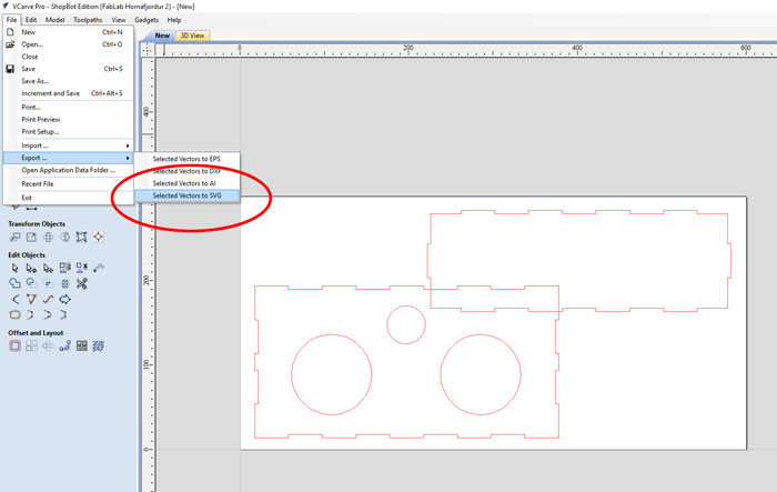
When importing a Sketch-Up file into VCarvePro and you want to use the outlines it is very important to select File / Import / Import Vectors. Don´t use Import Component or 3D model. If you do that the 3D drawing will not be a flat 2D lines in VCarvePro but a 3D model for 3D CNC milling.
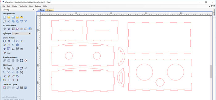
This is what we want, a flat 2D vector drawing of the robot head.
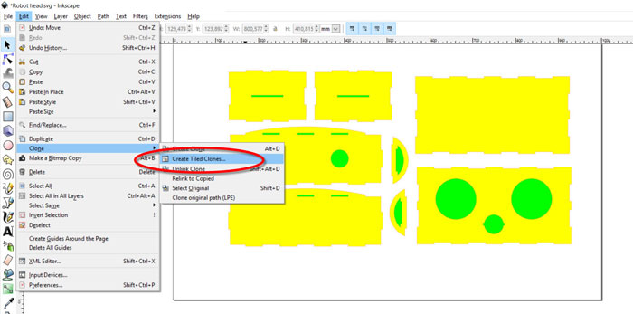
This is where the parametric work starts. Click on Edit / Clone / Create Tiled Clones.
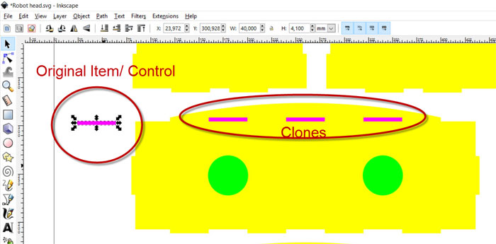
First I needed to test this method before I could go any further, so I made an original item that I would use for parametric control unit. Then I placed the three clones where they should be with the Object / Align and Distribute command. All sizes was the same as in the original drawing.
Then it was time to change the size of the original item and hope the clones will follow, bingo and they did.
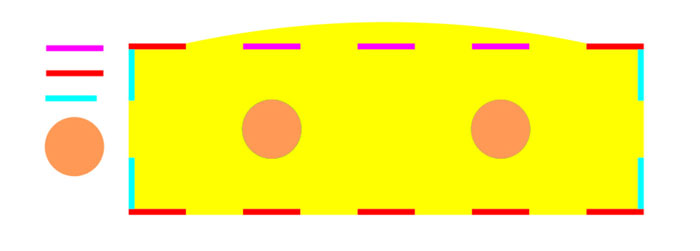
Next move was to make a control and clones for all joints in the purpose to make the top shape of the head parametric.
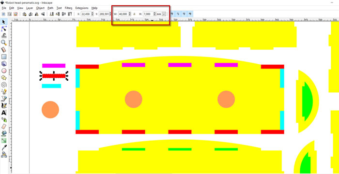
I changed each control unit thickness from 4,1mm to 7mm (see red window) and it worked out fine. I even changed the two circles with no problem. I just need to keep the old circles for the right alignment. To finish this work on the top panel I need to select all clones and click on Edit / Clones / Unlink Clones. This is very important when you start selecting each rectangles and cut the main shape with the Path / Difference command. This method works and can be helpful, but it´s not fully parametric.
Vinyl Cutting
Software used: Inkscape
Machine used: Roland Camm-1 Servo
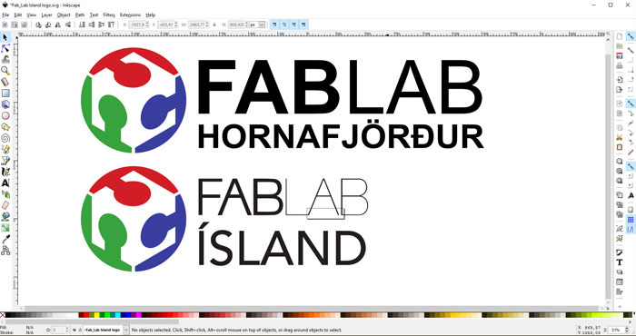
For vinyl cutting I wanted to test the rectangle method that can help when using more than one color.

So I drew three rectangles near the logo and the letters. Then I made a layer in Inkscape for each color. I took out all fills and made a 0.02 mm stroke on all layers. Then I saved a PDF file and started to cut out with the Vinyl Cutter.
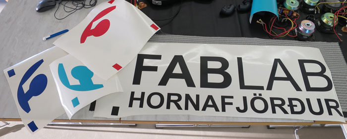
As you can see I had 4 files for each color and the rectangle dots for locating of the logo.
Vinyl Cutter settings (Roland Camm-1 Servo):
Force: 80gf
Speed: 20cm/sec
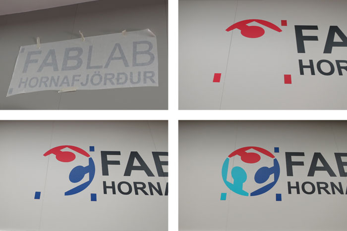
I had no problem sticking the logo to the wall and the dots were really helpful for right location.
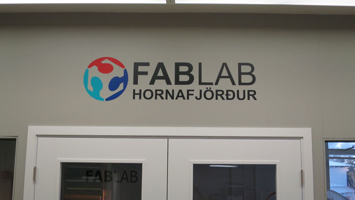
Here is the final outcome and everything is in place.
Related links
How to make a pressfit design in Inkscape Pressfit tutural Rhino
Pressfit tutural Sketch-Up
How to make a speaker
How to use a Roland GX-24 vinyl cutter