Computer-Controlled Machining
Assignment
- Make something big
For this week we needed to make something big in Fab Academy. What I did was working mainly on the neck of the Slide Guitar (my final project), which is fairly big. Before I started documenting I wanted to share with you other big projects that I have designed and milled out in our Shop Bot. First project is a circuit tree with Fab Lab logo that I made for our lab entrance. The other big project is a table that I design for computers and our Vinyl cutter. I did both of these projects before Fab Academy started.
Circuit tree with Fab Lab logo
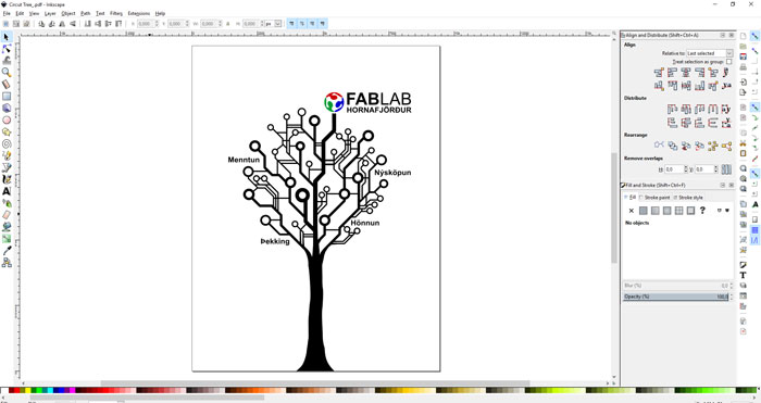
Fab Lab Hornafjordur is on the second floor in our Art and Craft house. In the entrance is a big wall that was ideal to put up an iconic picture with logo. I wanted to design something that would represent learning and technology. I thought a growing tree with branch reaching out would be ideal. Then came the idea to let the tree grow into some kind of circuits. I also wanted to use words that would represent our lab, words like education, innovation, knowledge and design. I draw up the three in Inkscape.
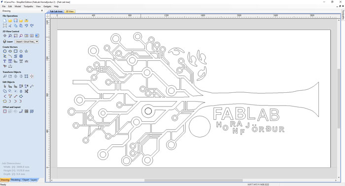
From Inkscape I exported the project into V-Carve Pro. From a V-Carve I made a file that I could use to mill out the three in 12mm plywood. I am not going to make a detailed documentation of these two projects, they are mainly for sharing purpose, if other labs or any one wants to use the files. I will make detailed documentation for the guitar neck.
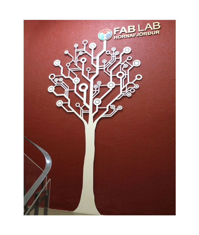
After cutting out the tree I painted it white, it took me three rounds to make it perfect. For the letters in the logo I decided not to paint it, just use the natural color of the wood. For the logo I used the vinyl cutter and putted a red, blue and green vinyl on the wooden Fab Lab Logo, shaped from the Shop Bot. In the end I glued the tree and the logo to the wall with very strong glue.
High table for vinyl cutter
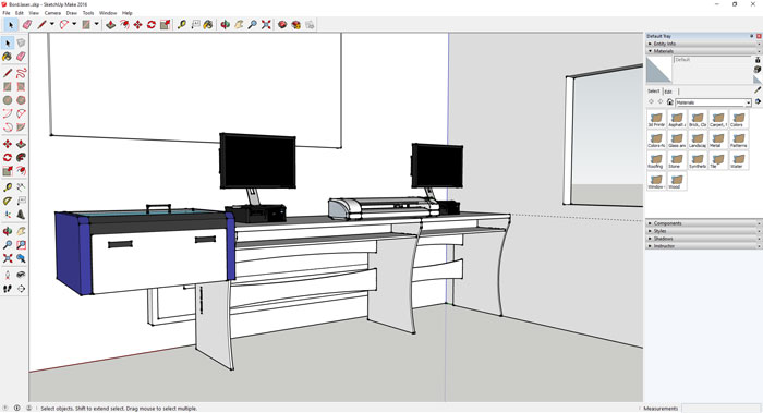
When I design the table I had three things in mind. I wanted people be able to stand and work on the computers, sending projects to laser cutter and vinyl cutter. I wanted a table that would fit the space and finally I wanted to have shelves that would stock small objects needed for the vinyl cutting process, like scissors, knives and so on. It was very helpful to draw up the space in Sketch-Up and put the vinyl cutter and laser cutter in for all measurements.
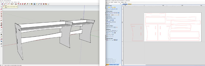
When I had designed the whole thing I hid all components in the drawing that I was not going to cut out in the Shop Bot. I carefully designed every unit as a “Component” in Sketch-Up. When this document was ready I saved the Sketch-Up file as an Sketch-up 2014 document and imported it in V-Carve Pro. I made two V-Carve out-put documents because the shelves were in 12 mm thickness plywood but the rest was in 15mm thickness plywood.
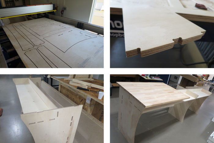
I carefully put dog bones on joints so it would fit perfectly and it did. I glued the table with wood glue and assembled all the pieces together. Finally I put the 25 mm wooden top plate that I had bought from a local hardware store.
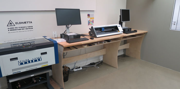
Here is the table ready for use. The table is sturdy and exactly in the right height for people to work on. If you are interested to use the drawing be careful because I used two thickness of plywood 15mm and 12mm, yes I was short on material.
Slide Guitar neck
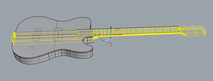
Like I said above I wanted to use this week for milling the neck of my Blues Guitar. It´s a two side milling and the process is quite complex. In the end I will need 3 programs to make it happen; Rhino, PartWorks 3D and V-Carve Pro. I opened the Rhino document from Week 2 and made a new document. I hid layers with the body and the fingerboard so I only could see the neck.
In this new Rhino document I made a copy of the neck and measured the two holes for the Truss Rod. The truss rod stabilizes the lengthwise forward curvature of the neck. Like in my case it is a steel bar or rod that runs inside the neck, beneath the fingerboard. I will not use this 3D document with the holes when I mill the neck out, I will mill the two holes from 2D Lines in V-Carve Pro. So this is just for me to see the location and the depth of the holes.
Because this project is a two sided milling process I did need to send two STL files to the Part Works 3D to generate a 3D file for V-Carve Pro. I don´t want the 3D file to mill out all the neck, because the milling in 3D is slow. Some parts will be cut out after 3D STL files and the rest will be cut out after 2D lines in V-Carve Pro. So I started to cut off part of the 3D drawings that I don´t need for the 3D milling. Then I selected the item that I wanted to export and hit "File / Export Selected" and saved the part as a STL file.
Then I needed to make two more files for the process. I needed outline of the neck and also lines for the cut out on the back side of the neck. I exported all lines as DXF out of Rhino. Then I needed to export another STL File for the head stock. To get outline from a 3D object in Rhino click on "Curve/Curve From Object/Mesh Outline". Just remember to be in the right view when you do that, in my case I was in Top view

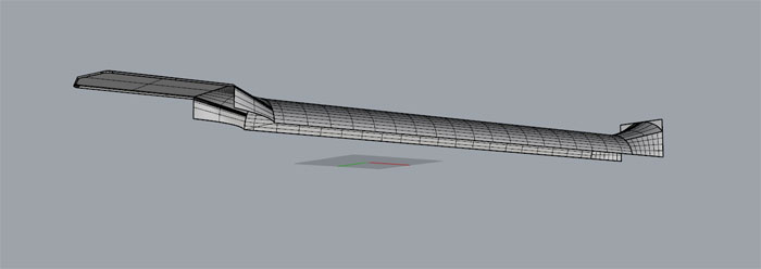
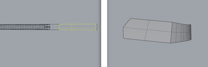
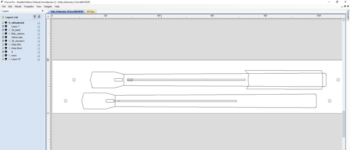
Here are the shapes and lines that I exported out of Rhino, two STL(3D) and one DXF (Lines). I did not export the top object on the picture. That is just for you to see witch part I did export and which part I did not export. There is one thing missing on this picture and that is the holes for the truss rod, I just made them in V-Carve Pro.
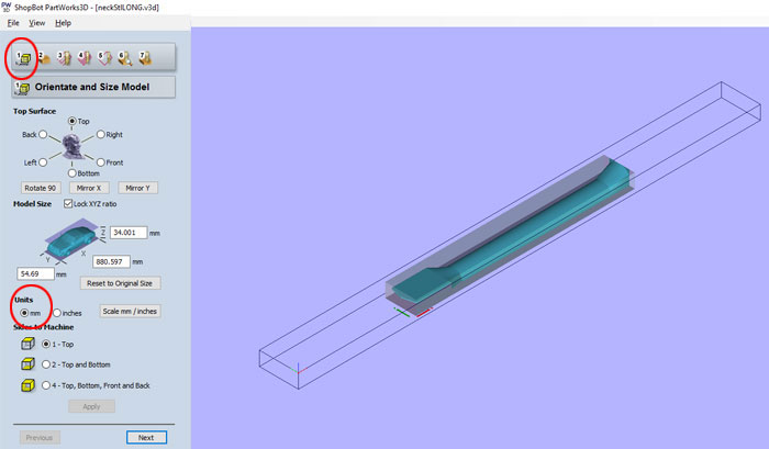
Next thing was to import the STL file (side 1 milling) into Part Works 3D and work through the seven steps to get a 3D milling file. In step ONE I set the document in millimeters. Since I make Part Work 3D file for each milled side I picked "1-Top" in "Sides to Machine" option. Now I was ready for the next step.
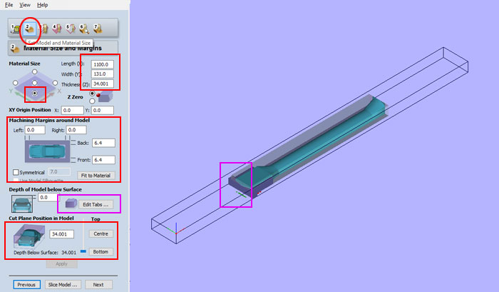
In step TWO there are few things to have in mind. First I set the thickness of the material I was going to use 34mm. Then I needed to set the location of the zero point for X and Y position. (XY Original Position option). In "Machining Margins around Model" it´s very important to have right settings because I was not going to mill the whole neck with the 3D document. I set 0.0 to left and right and set 6.4 to back and front. So in this case the machine would not cut through where the 3D document ends. After setting those settings I needed to add Taps, see "Edit Tabs" button. I only added taps on the front (head stock) because I will add taps in V-Carve Pro later for the back side. It takes time to set the taps and I wish it would be easier way to do it in PartWorks 3D. Last but not least in step 2 I set the "Cut Plane Position in Model" to the button. Normally it´s good to have Cut plane near central when you are milling two sides with one Path Works 3D document, but we are using two Path Works documents to mill two sides so we set the cut plane to the button.
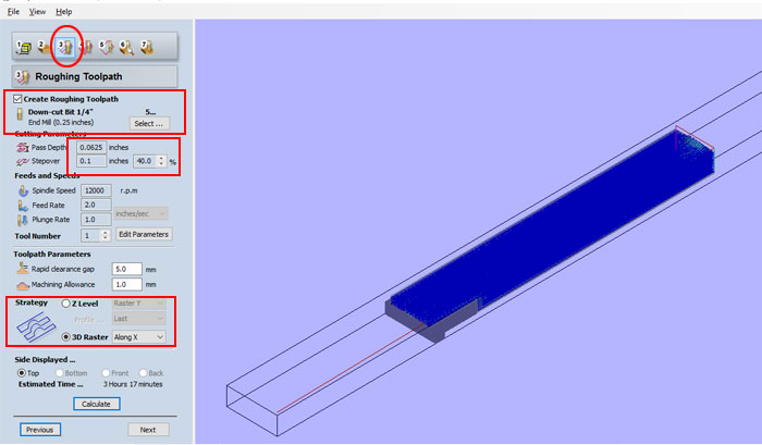
In step THREE I needed to pick the drilling bit I was going to use for "Roughing Toolpath". The Roughing Toolpath clears away most of the material for the Finishing Toolpath. I picked 0.25 inch 1/4 Down Cut End Mill (ONSRUD 57-287) for the job and adjusted the "Feets and Speeds" setting: 12000 r.p.m. "Spindle Speed". 2.0 "Feet Rate" and 0.1 Plunge Rate. In Toolpath Parameters I picked the 3D Raster Along X for path strategy. Picked "Top", hit "Calculate button" and went to the Next step.

In step FOUR I defined which milling bit I was going to use for the "Finishing Toolpath". I picked Ball Nose 0.25 Inch. For "Feet’s and Speeds" I used these settings: 12000 r.p.m. "Spindle Speed". 2.0 "Feet Rate" and 0.1 Plunge Rate. In Toolpath Parameters I picked the 3D Raster Along Y for path strategy, then went on to the next step.
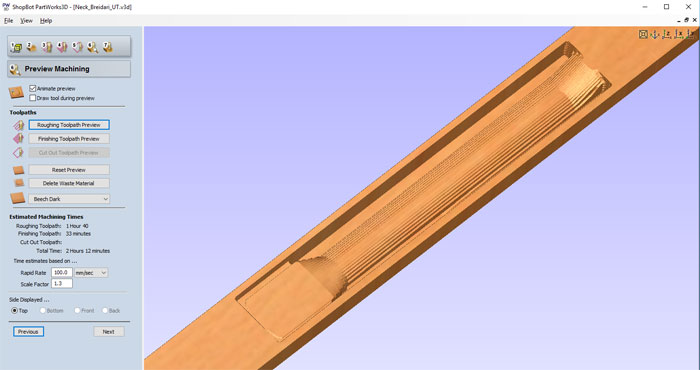
This is how the "Roughing Toolpath" preview looks like. The "Finishing Toolpath" was looking good so I could save the file as PartWork 3D file.

I imported the STL file for the head stock. I used the same method in PartWork 3D.
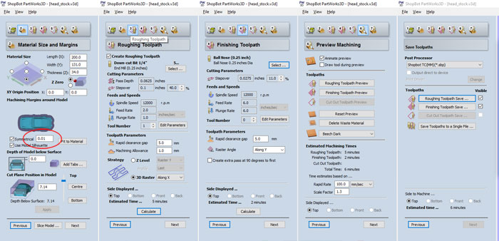
Here are all the settings for the head stock part. For Machining Margins around Model I used the setting 0.01 Symmetrical.
In V-CarvePro I imported all lines for the neck from Rhino 3D. I made holes to cut into the sacrificial layer of the Shop Bot and another holes that I cut into the neck material.

Then I imported the PartWorks 3D file with the 3D into the V-CarvePro. I placed the neck gray 3D path below, that was the first milling. Then I placed the headstock part and used it when I had milled the first part and turn the material around (Two side milling). I used a pin method to get the right location for the two side milling. I drilled holes into the work bench of the shop bot and then I drilled another holes into the material. (Same distance between holes but not same location).
When I had milled the first side I rotated the material like I talk about above and put the pin in it and placed it into the holes in the work bench. There is a reason why I did not use the same location when I drilled the holes into the work bench and the holes in the material. I wanted to see both sides in the document without using layers. That gives me good overview what I am milling on each side.
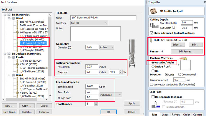
This images is showing the settings for the 2D milling, cutting the outline and holes. This is the number of the End Mill I used Onsrud 57-287 it has the same width as 1/4" 57-910 but it´s longer. On that time I did not have the 57-287 in my tool database.
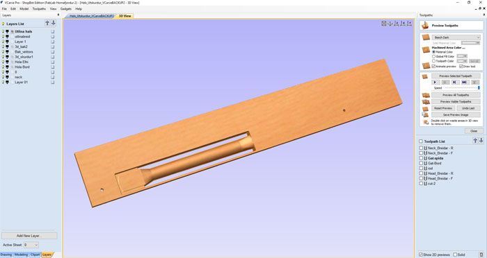
This is the first milling part, only made with the PartWorks 3D file. When this part was ready I turned the material around and kept on milling on that side.
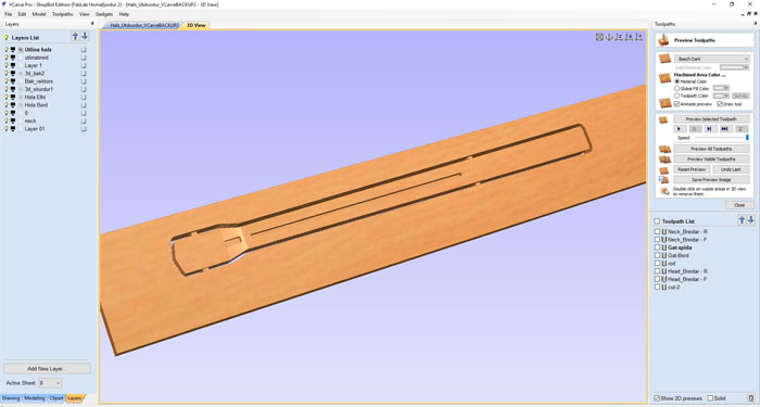
This is the second side when I had turned the material around and milling the headstock in 3D and the outline in 2D. I used 6 screws to keep the material in place or stuck to the work bench of the Shop Bot.

Milling bits used in the project: For Roughing Tool Path, End Mill Onsrud 57-287. For Finishing Toolpath I used the Ball Nose Onsrud 52-280BL.
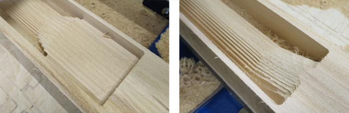
This is when the Shop Bot has finished the "Roughing Toolpath" on the first side. I took out the End Mill from the collet and placed the Ball Nose for smoother finish.

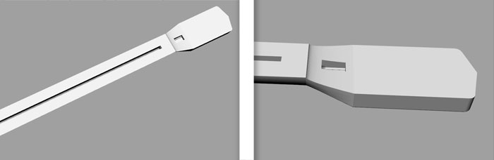
Here is the final outcome from the Shop Bot. Beautiful piece ready for sanding. I placed the Tross Rod and drilled a hole between the pockets. It was a perfect fit.
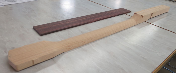
Here is the neck rotated 180 degrees. I will need to sand down the taps and some rough parts after the Ball Nose. Over all I was happy about the process and now I could finish the design of the guitar body.
Related links
VCarve Pro 8.0 for BeginnersTwo Sided Machining
D08 - Two Sided Machining
PRS: 3D Carving
How to use the Shopbot