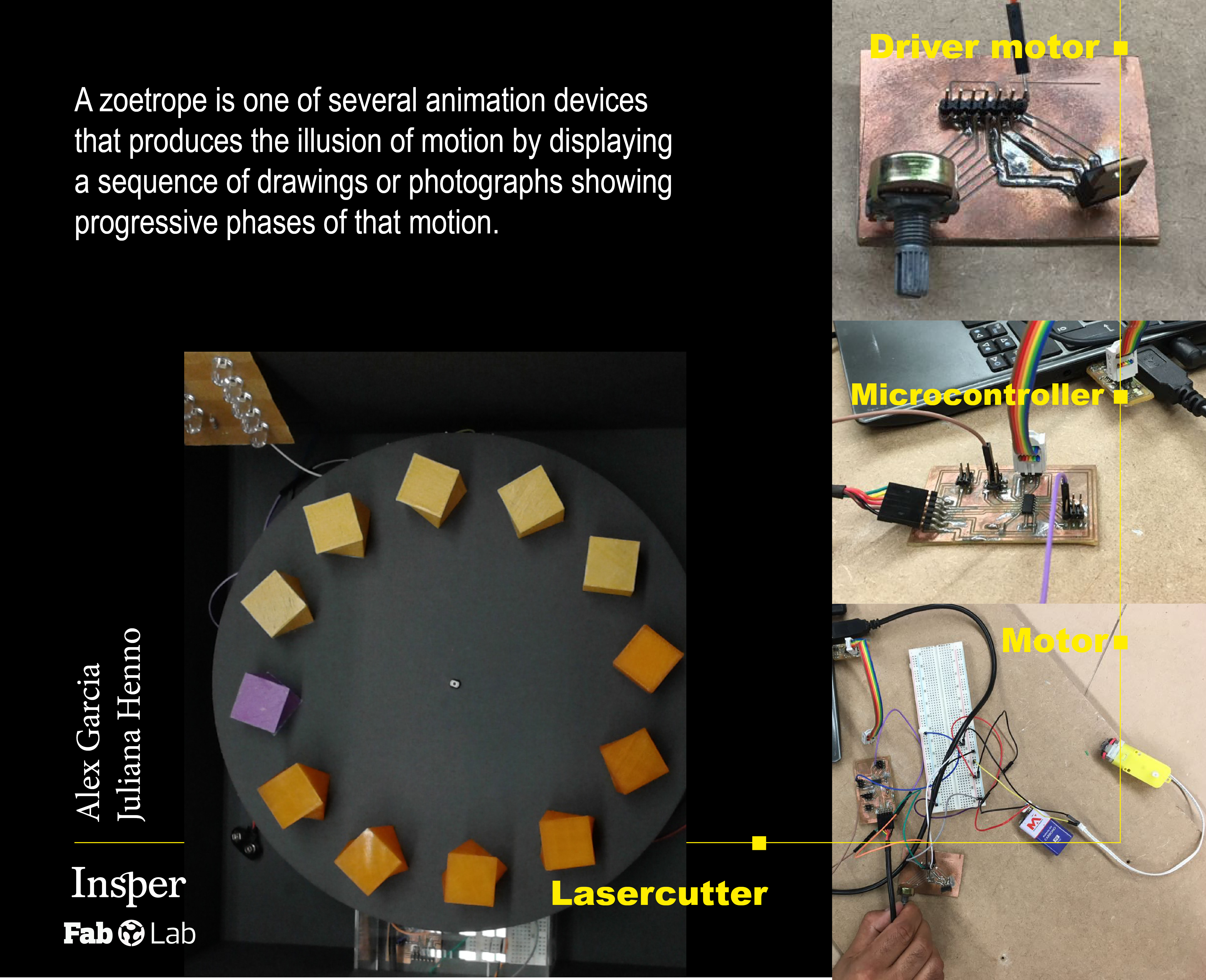
The final project that me and Juliana Henno (also a continuing student from FabAcademy 2013) chose to make is a 3D Zoetrope. The idea of the 3D Zoetrope is that we could build a motorized platform that could be adjusted in relation of the blinking LED. The strobe effect generated by the blinking LEDs will cause an illusion of a camera shutter in which the flickering image(s) on the platform will give an idea of being in a constant motion without any breaks or intervals. In order to amplify the contrast between darkness and light, the platform was projected to be enclosed inside of a container. This way, the light would be blocked from outside and the only brightness inside would be provided by the Strobe blinking effect. Another reason we decided to go for this project is that it encompasses most of the assignments previously made in the course. As it will be clear in the topics below, assignments like Computer-Aided Design, Computer-controlled Cutting, Electronics Production, 3D Scanning and Printing, Electronics Design, Embedded Programming, Machine Design and Output Devices.
To do the microcontrollers board and motor driver, I worked with this assignments:
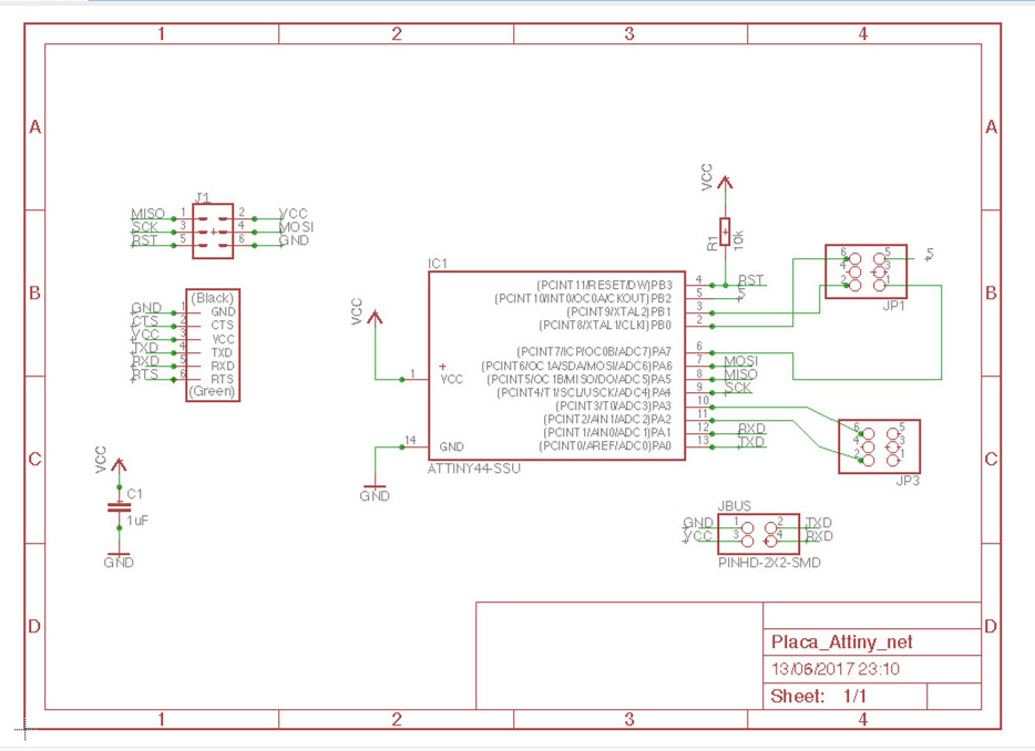
Eagle schematic
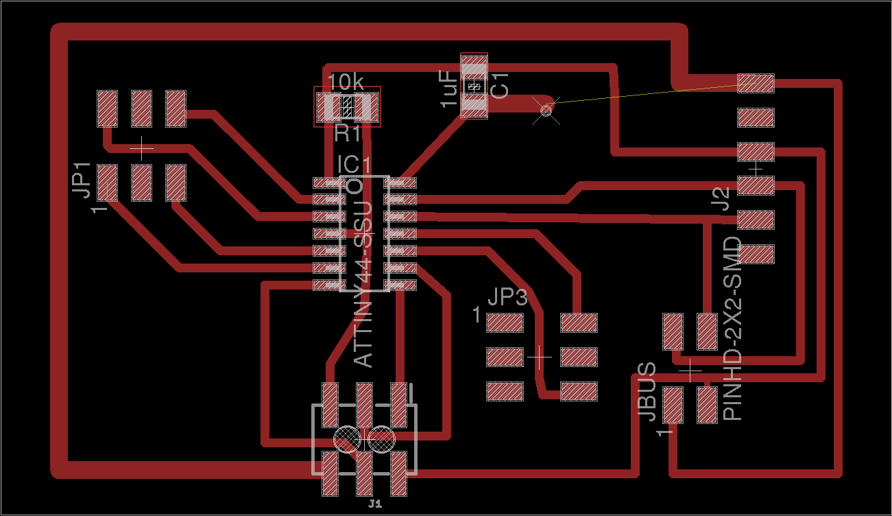
Eagle board
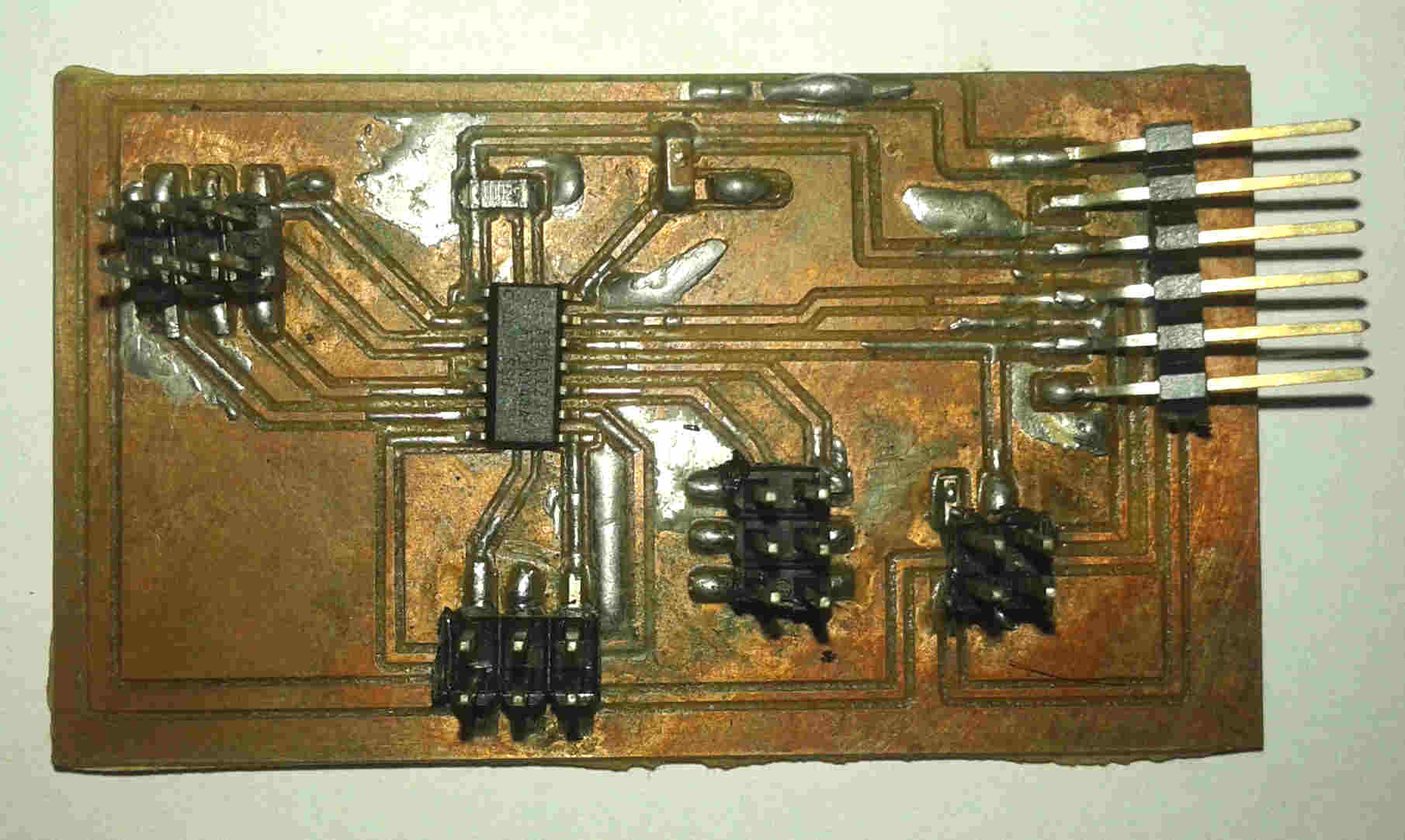
Final Board
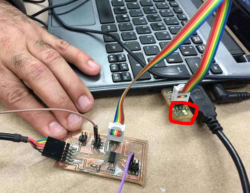
Programming board
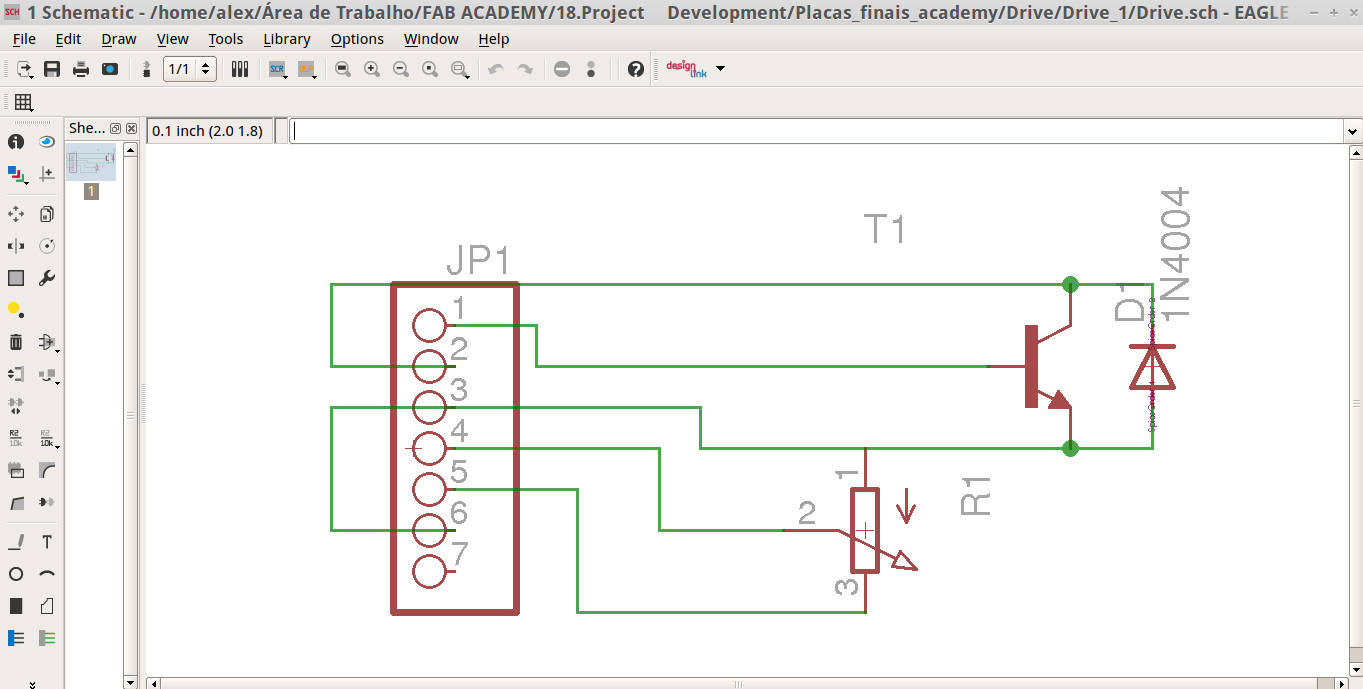
Eagle schematic
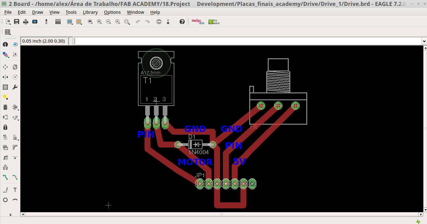
Eagle board
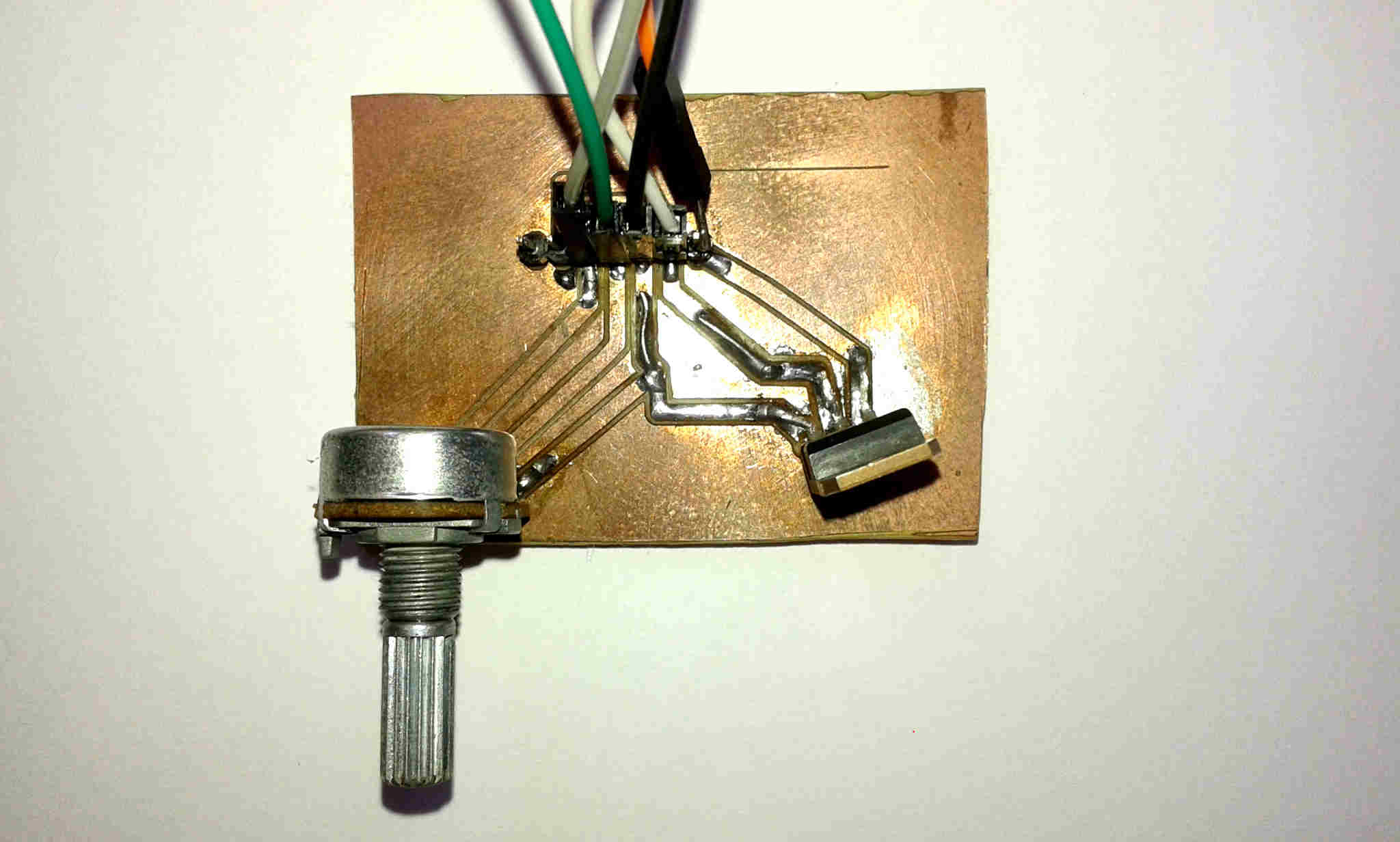
Final board
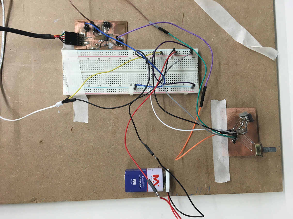
Micro + drivers + motor
Programming the board/driver Output
To programm the board/driver I modified (adapting to Attiny44 board and serial communication) an Arduino example with my tutor Kenzo Abiko help, this is the code:
/* Created 29 Dec. 2008 modified 9 Apr 2012 by Tom Igoe modified October 2017 by Alex Gacia And Kenzo Abiko This example code is in the public domain. */ #includeSoftwareSerial mySerial(0,1); // RX, TX const int analogInPin = A3; // Academy driver potentiometer is attached to const int analogOutPin = 8; // Attiny Board output pin that the motor is attached to int sensorValue = 0; // value read from the pot int outputValue = 0; // value output to the PWM (analog out) void setup() { // initialize serial communications at 9600 bps: mySerial.begin(9600); } void loop() { // read the analog in value: sensorValue = analogRead(analogInPin); // map it to the range of the analog out: outputValue = map(sensorValue, 0, 1023, 0, 255); // change the analog out value: analogWrite(analogOutPin, outputValue); // print the results to the serial monitor: mySerial.print("sensor = " ); mySerial.print(sensorValue); mySerial.print("\t output = "); mySerial.println(outputValue); delay(100); }
InPut-OutPut from Alex Angelo on Vimeo.
The network/communication between the controller boards (LED and Motor) to syncronize the base movement and the light effect, was not able to do. I need more technical expertise to understand the network/communication using Attiny 44A. I had difficulties with the Arduino IDE libraries as described in my network/communication assignment. This assignment I succeed in blink a led board as a slave, but not sync the motor and the LED array.
To build the platform I worked with this assignments:
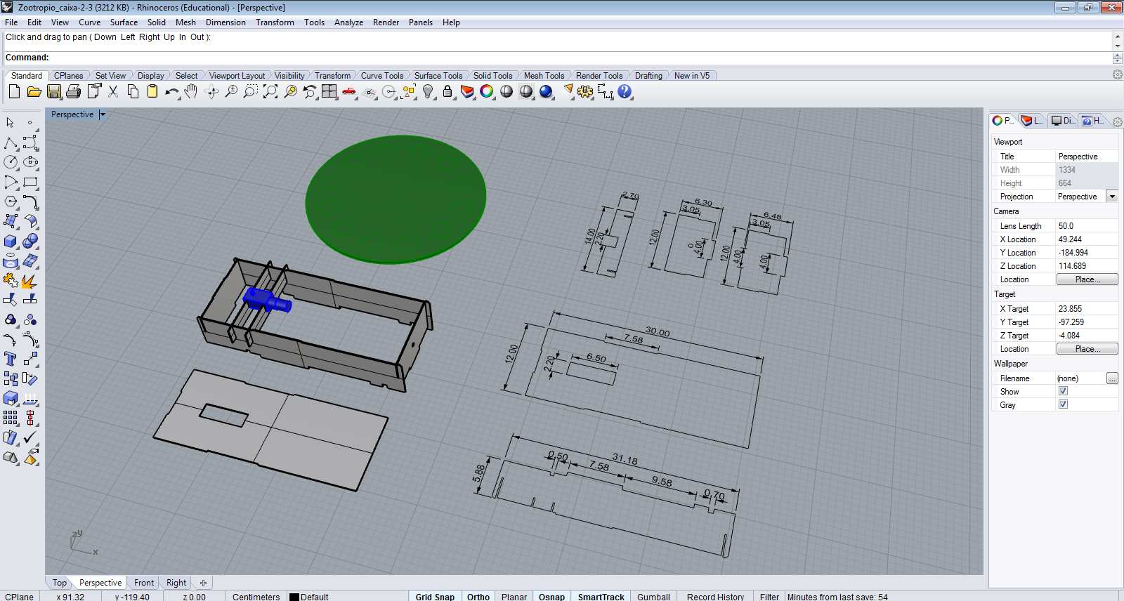
3D design
3D design complete (with Juliana Henno)
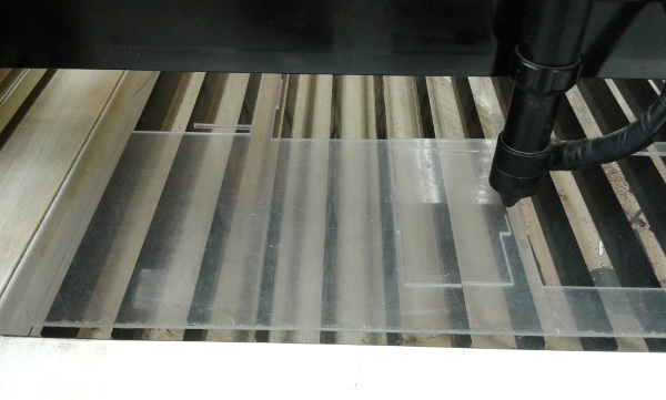
Fabricating the acrylic box
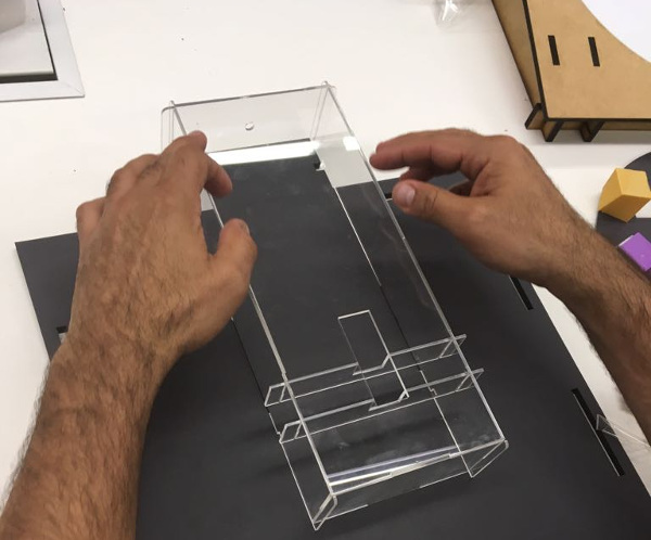
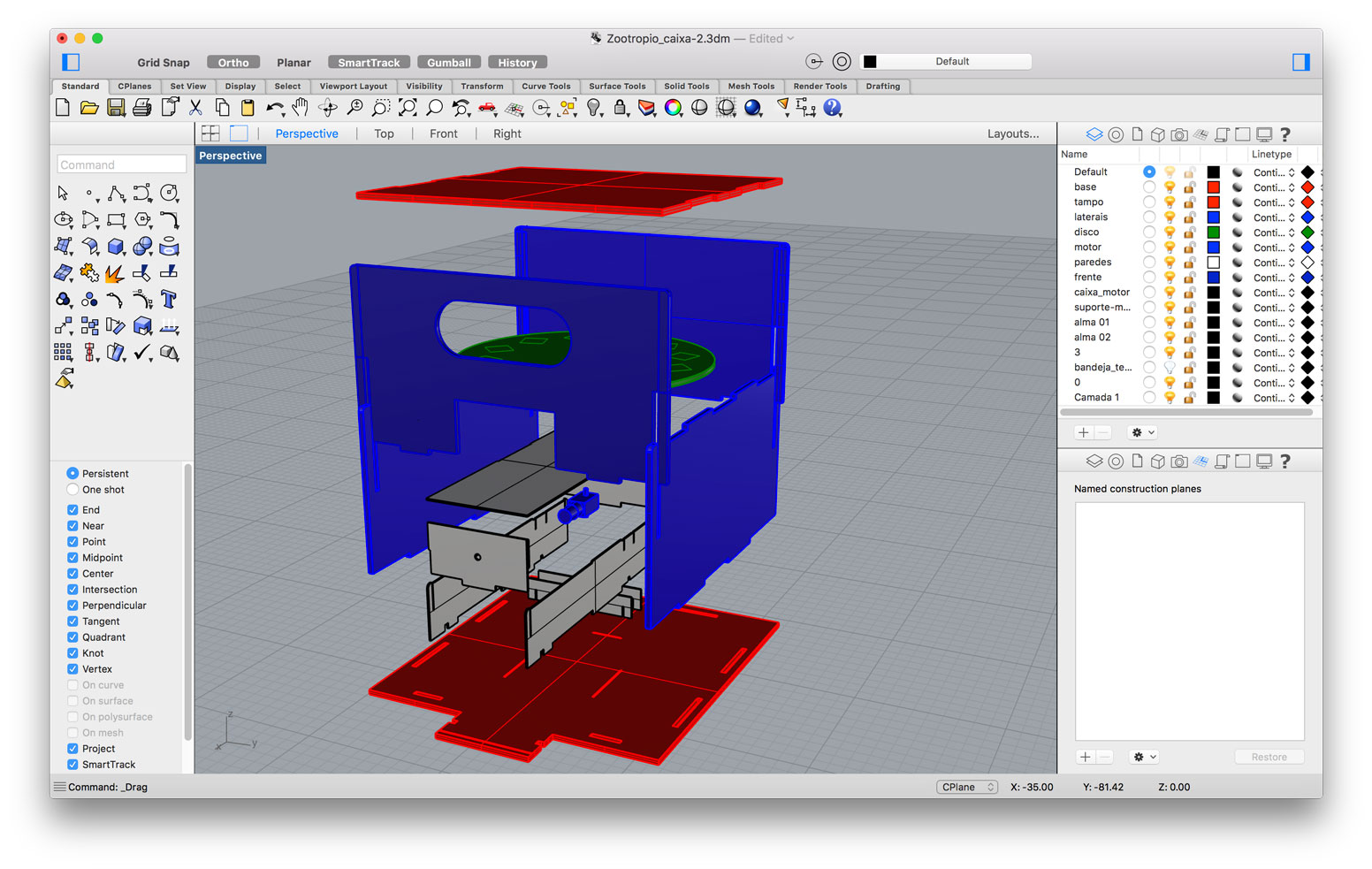
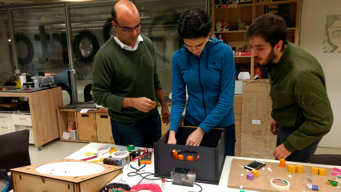
Assembling the acrylic box
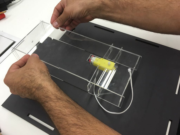
Assembling the acrylic box + motor
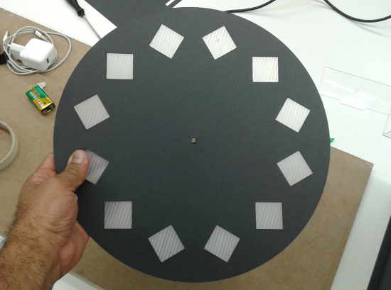
Platform
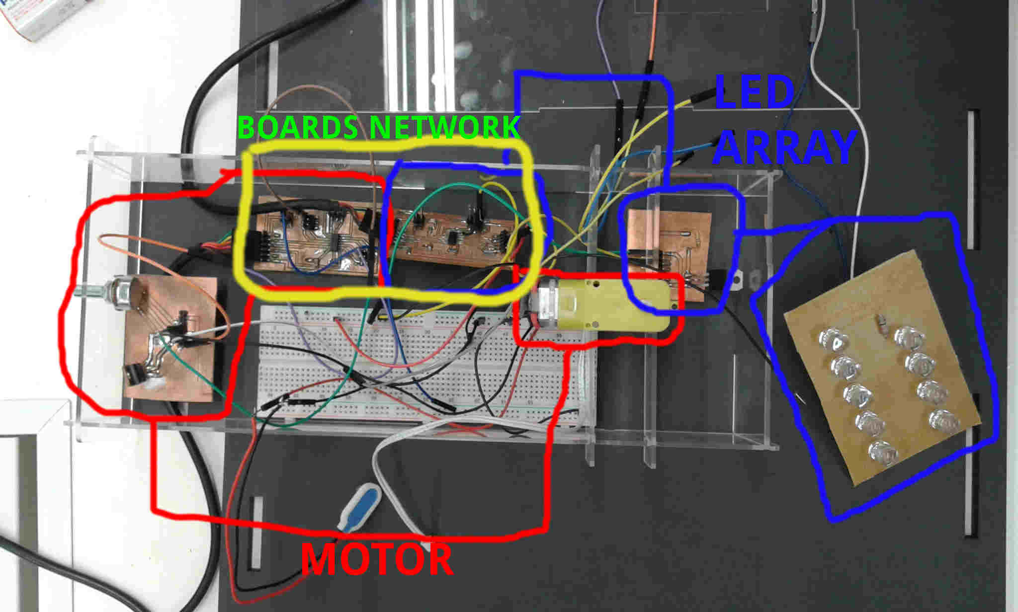
Placing the wires and boards in the acrylic box
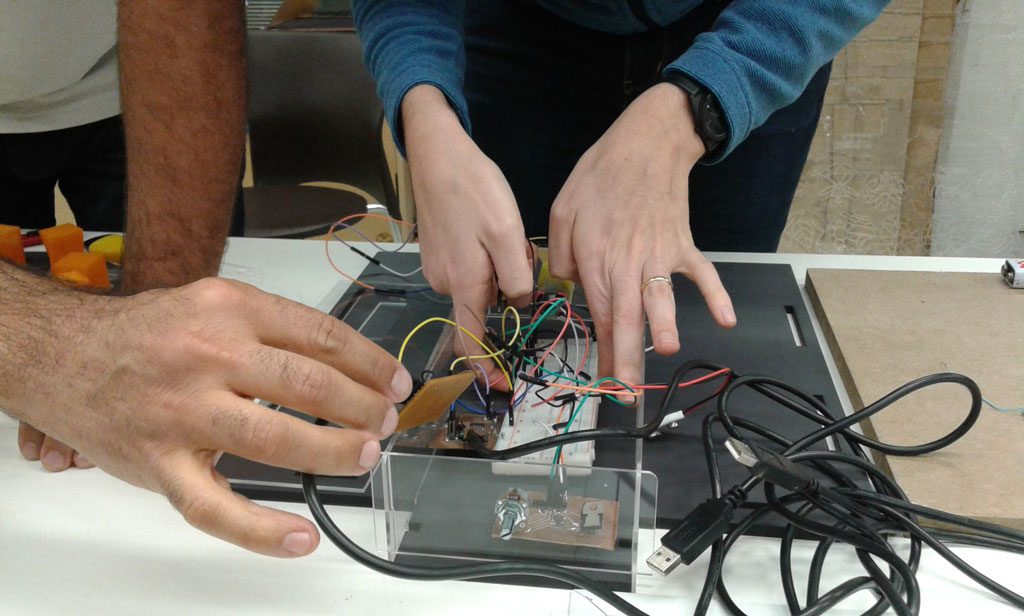
Placing the wires and boards in the acrylic box
Motor Potenciometer from Alex Angelo on Vimeo.
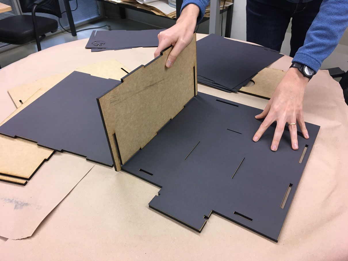
Assembling the container
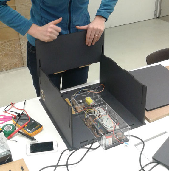
Assembling the container
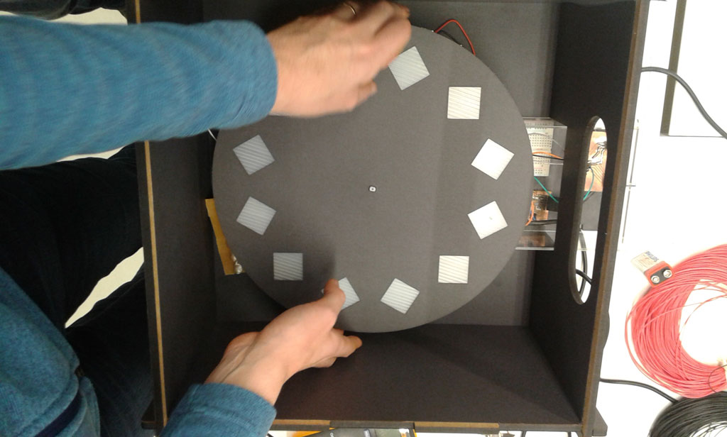
Placing the platform
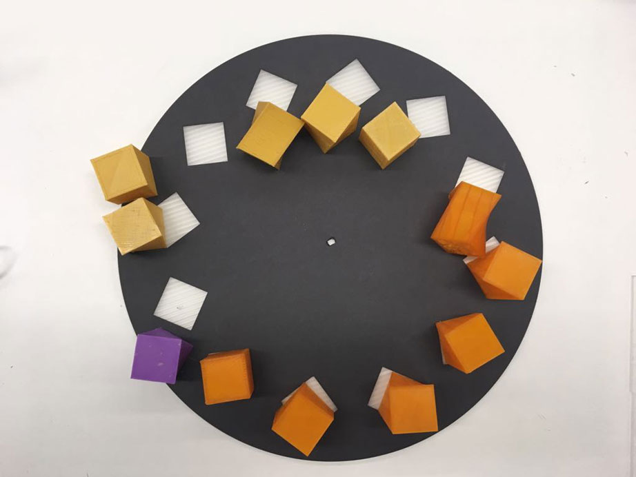
3D models before being fixed on the platform
Placing the platform
Placing the platform
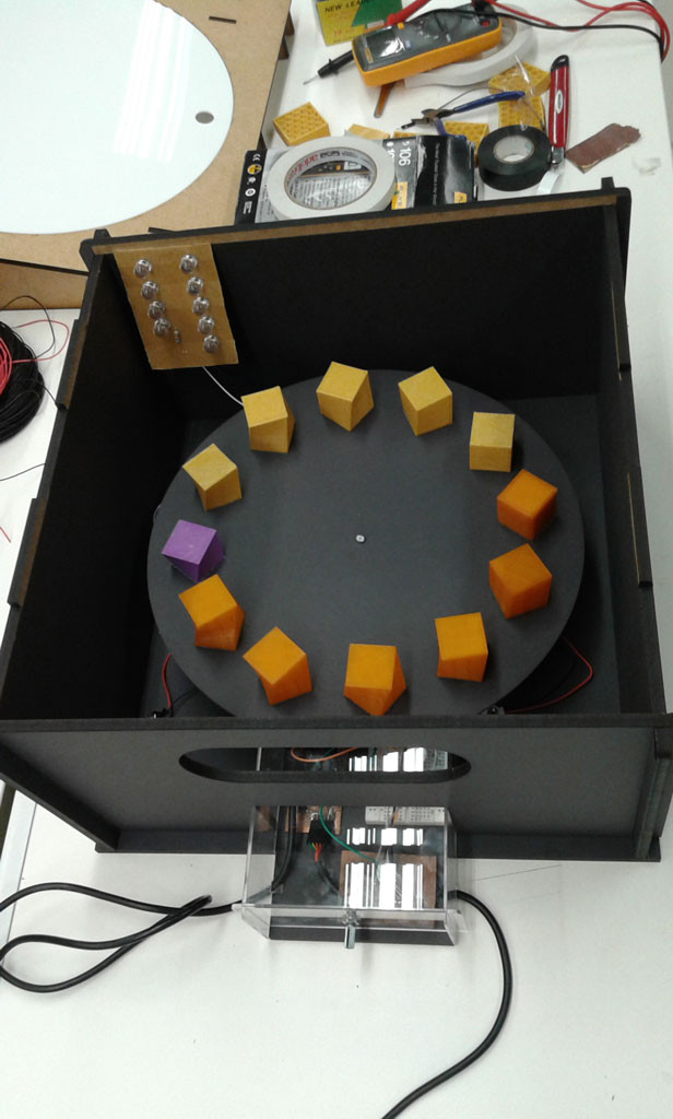
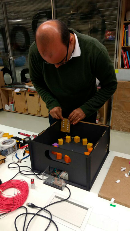
Fixing the LED array boardm
1mx1mx6mm MDF panel
PLA filament (1.75mm)
50cmx20cmx2mmAcrylic
Juliana Henno Microcontroler board
Alex Garcia Microcontroler board
Juliana Henno set of boards of LED array
Alex Garcia board of motor
Power Supply 12V
Machines Used:
Laser cutter
3D printer