
My final project with my colleague Juliana Henno, The Fab Zootrope need a microcontroller (here explained), a motor/potenciometer driver (Output here explained).
My tutor Kenzo suggested me to redesign the HelloBoard/Attiny 44 to make a microcontroller.
I studied the 2015 Fab academy´s output Saverio that help me to know how to use a potenciometer and to make a drive with components as L293D drivers. Some SMD academy´s components is not easy avaiable, but PIC drivers are more easy to get and can be controlled by an Attiny.
I have to apply what I had learned in my electronic prodution and electronic design assignments, let´s begin with the microcontroller board.
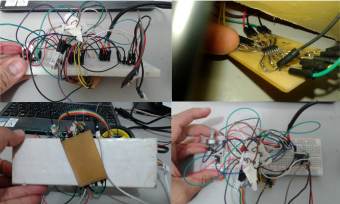
I tried to test my board before to mill it, by myself, I wanted to use the homemade PCB thermal transfer to adapt the Attiny44/SMD to a breadboard.
It was a mess... but even so,to my surprise, It was programmed with my FabTinyISP!
Well, too much work and just to understand the board and the homemade PCB .
After my experience in Electronic production and mainly in Electronic design, I worked to understand more about the Attiny 44A to design my microcontroller board. I chose the 44A because have more pins than 45. I studied the hello board and attiny44's pin out to design a "minimal microcontroller board" to my motor drive.
Hello board and "minimal microcontroller"
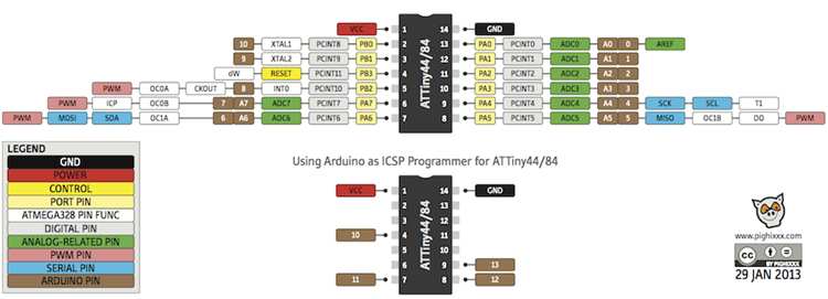
44A Attiny´s pins
After studing Attiny44 pins and Hello Board I worked in Eagle to design a microcontroller board that could use all avaiable Attiny pins and communications(network)
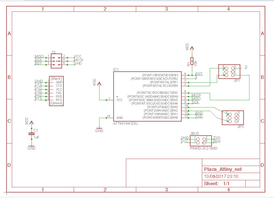
Eagle schematic
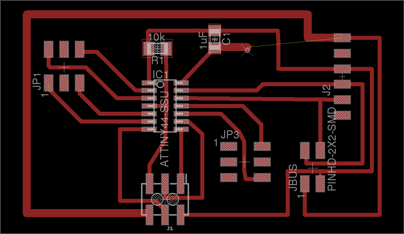
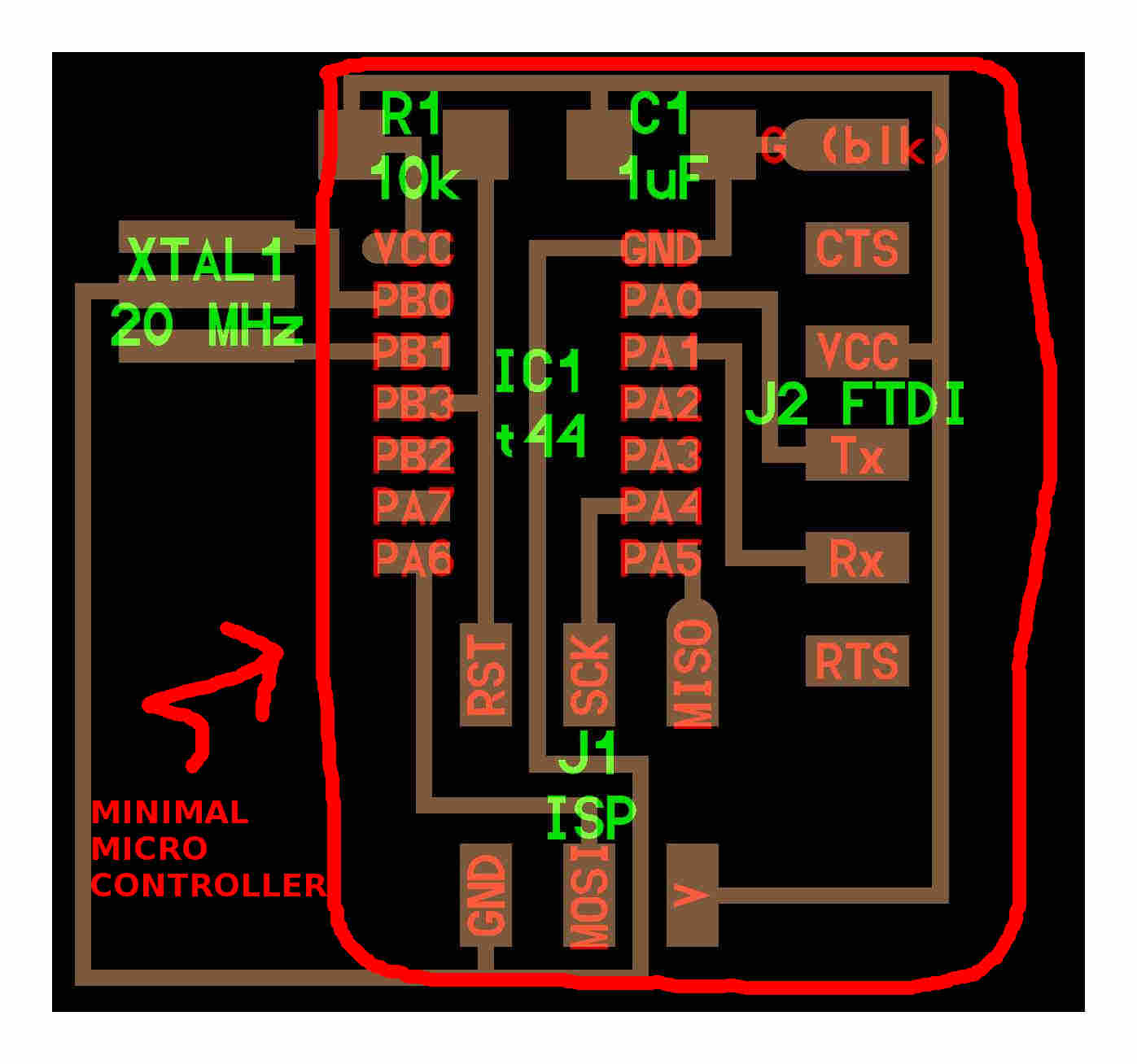
My "minimal microcontroller board"
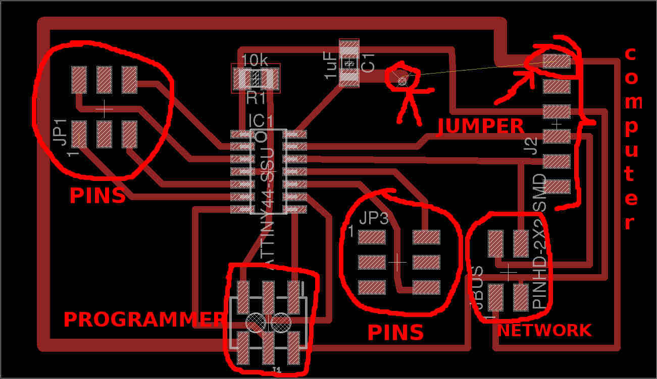
Minimal microcontroller board explained
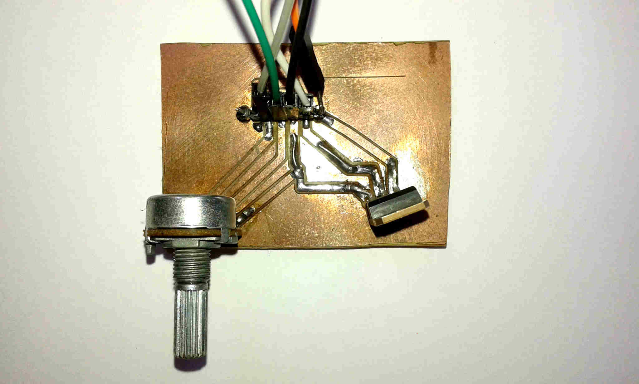
After processed the file in Eagle, Gimp and Fab modules as described in my assignment Electronic production, I solded it and then the result.
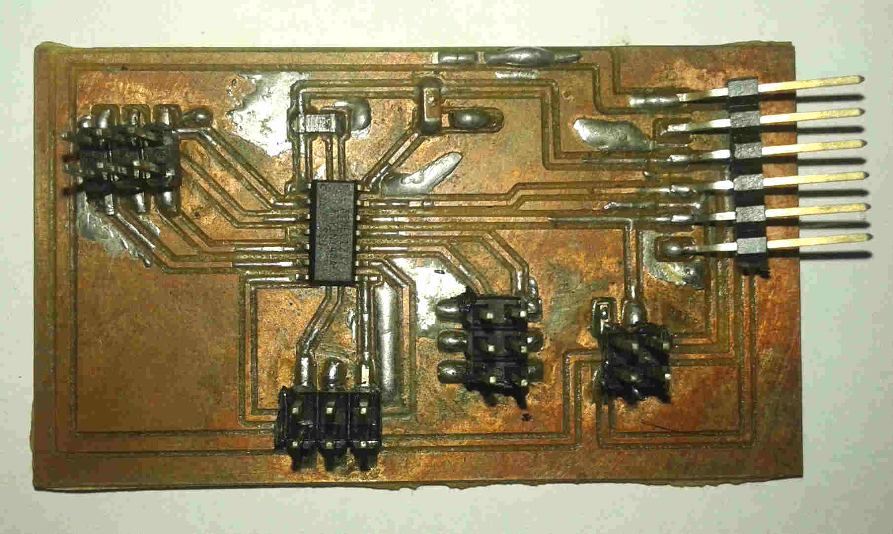
The microcontroller board.
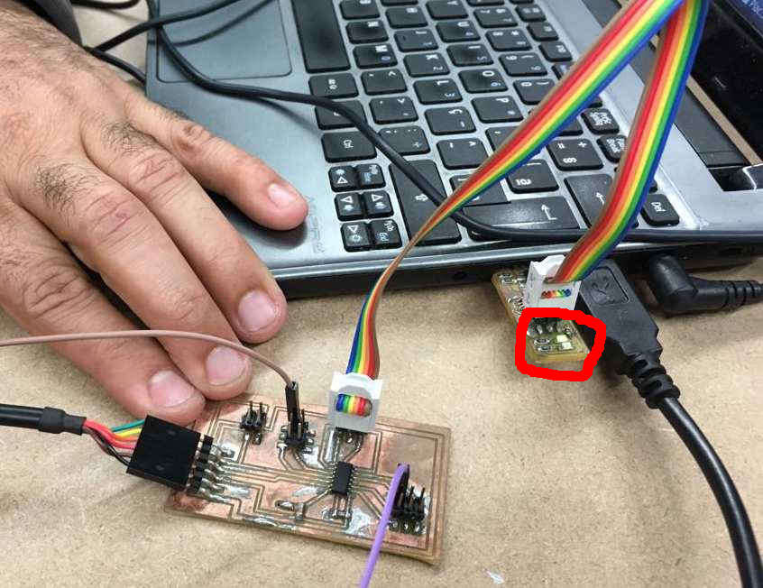
Green led on when connected to FabISP: board ready to program.
I researched about potentiometers drivers and motors. After doing the arduino schematic I realized that the a 555 timer driver with TIP 122 only changes the velocity direction and I needed to control it.
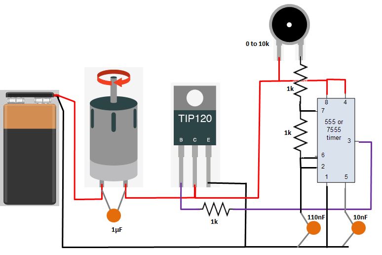
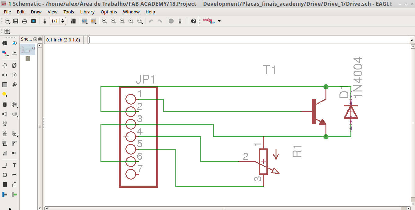
Studying more examples to control one motor (output) with a potentiometer (input) I take this driver using a transistor TIP 122 and a potenciometer.
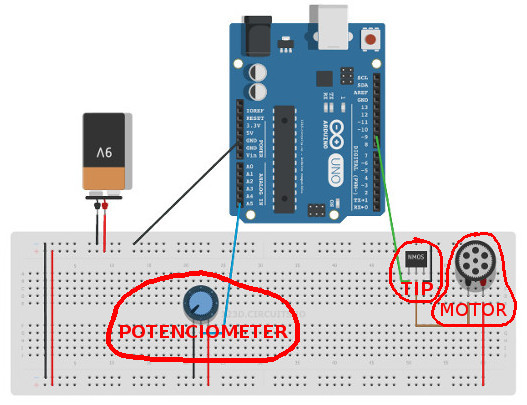
The schematic with arduino
This is my test to understand the schematic using Arduino.
Testing the schematic with arduino from Alex Angelo on Vimeo.
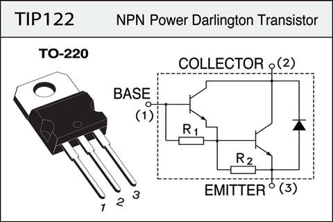
After decided to work with TIP 122 and a Potenciometer I studied the TIP 122 datasheet to help me to understand the pins.
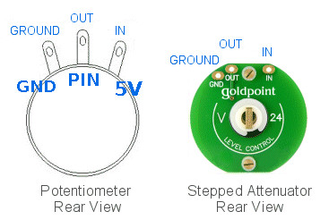
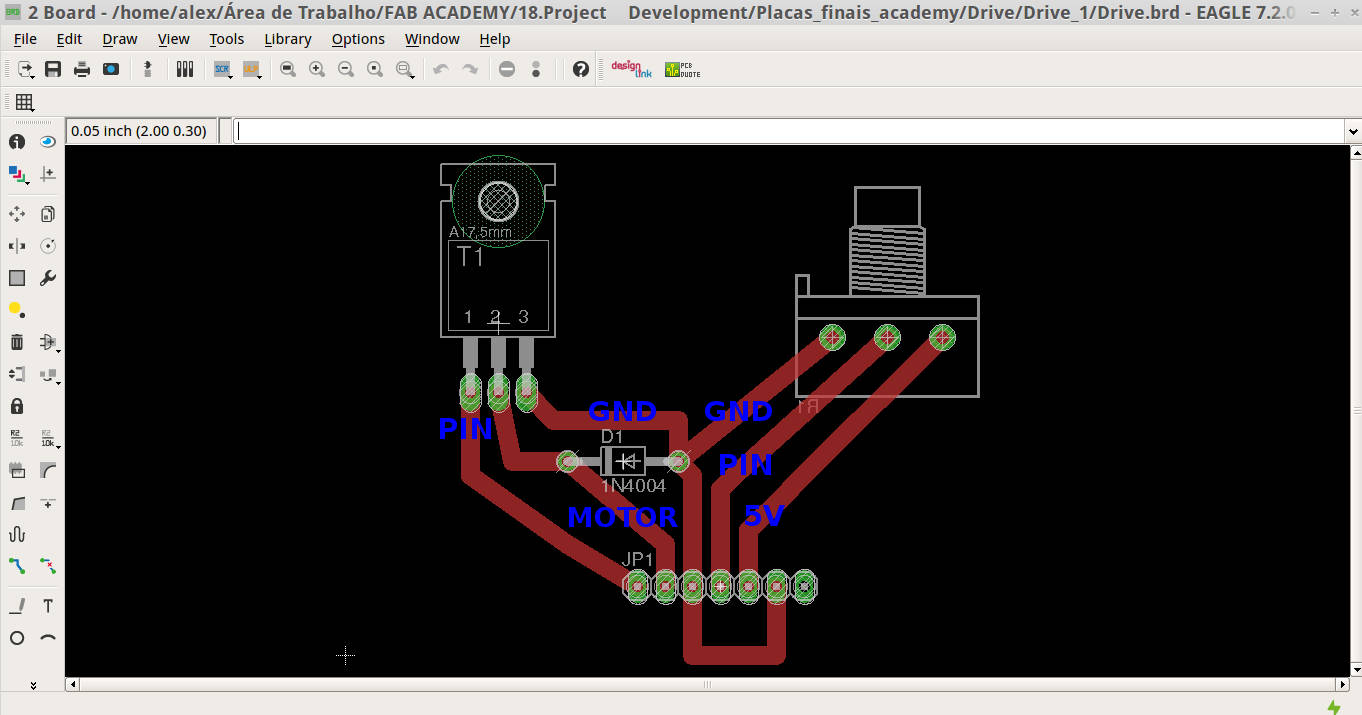
The potenciometer´s 1, 2, 3 PINs. wil be connected to GND, PIN and 5V boards respectively.
Working with my colleagues from Insper Fab lab, they adviced me to use a diode, that conducts primarily in one direction (asymmetric conductance). between the ground and motor trace.
Materials
To programm the board/driver I modified (adapting to Attiny44 board and serial communication) an Arduino example with my tutor Kenzo Abiko help, this is the code:
/* Created 29 Dec. 2008 modified 9 Apr 2012 by Tom Igoe modified October 2017 by Alex Gacia And Kenzo Abiko This example code is in the public domain. */ #includeSoftwareSerial mySerial(0,1); // RX, TX const int analogInPin = A3; // Academy driver potentiometer is attached to const int analogOutPin = 8; // Attiny Board output pin that the motor is attached to int sensorValue = 0; // value read from the pot int outputValue = 0; // value output to the PWM (analog out) void setup() { // initialize serial communications at 9600 bps: mySerial.begin(9600); } void loop() { // read the analog in value: sensorValue = analogRead(analogInPin); // map it to the range of the analog out: outputValue = map(sensorValue, 0, 1023, 0, 255); // change the analog out value: analogWrite(analogOutPin, outputValue); // print the results to the serial monitor: mySerial.print("sensor = " ); mySerial.print(sensorValue); mySerial.print("\t output = "); mySerial.println(outputValue); delay(100); }
OutPut from Alex Angelo on Vimeo.
Drive.sch motor file is the schematic file.
Attiny44_board.brd file minimal microcontroller board file.
Attiny44_board.sch file the minimal microcontroller schematic file.