
I followed the Dinesh Auti tutorial with adaptation to run Eagle in Trisquel/Linux, unfortunately this is not more available. But,if you use Linux you can see the autodesk tutorial , It was very similar that I did.
After downloaded and put the Eagle folder in my /opt, I went to terminal and I did this:
alex@alex-V5-171:/opt/eagle-7.2.0/bin$ ./eagle
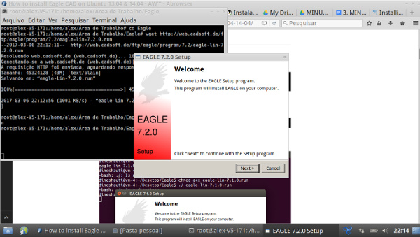
The Eagle ran and the version was 7.2.0.
To work with the Eagle I followed this Fab Academy tutorial and downloaded the echo board schematic and the fab.lbr files here.
I opened the file schematic and begin to add a LED, two Resistors, a Button, two Grounds and one VCC.
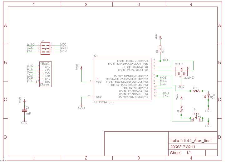
And then, I did the connections and switching to board .
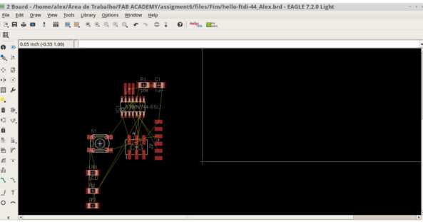
Changing to "board view" I began to move the components to build the circuit. I used so much the automatic Eagle function 'autorouter' and manual changes to fit the drawing.
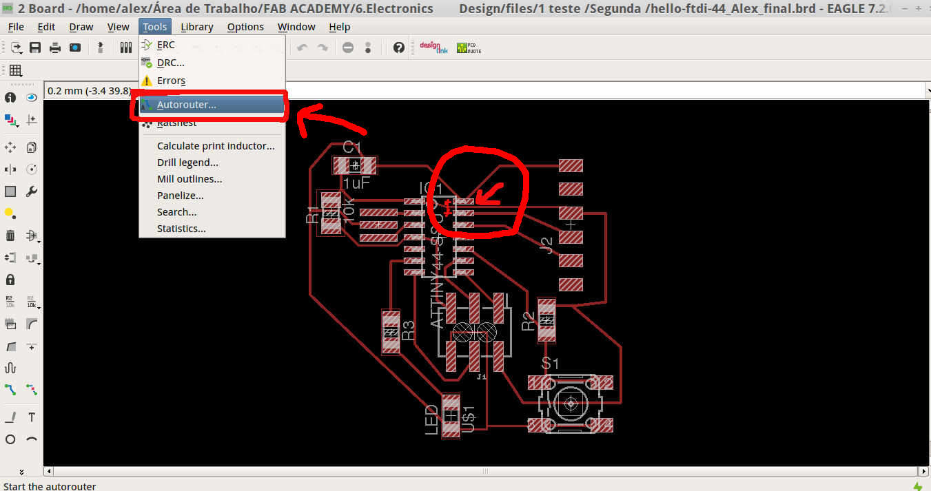
To final fit, using the autorouter suggestions, I decreased one wire width using Eagle panel: " Edit/Change/Width " to 0.2mm, because it was "crossing below the Attiny". This was a suggestion from our tutor Kenzo.
With this board, I began to fabricate it.
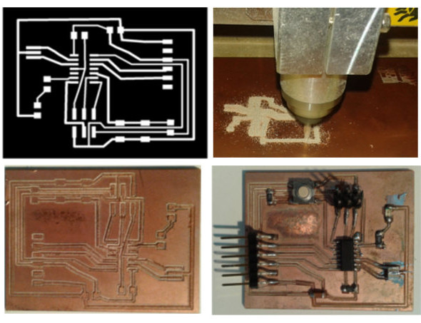
After generate the board file, I exported to .png with 500 dpi.
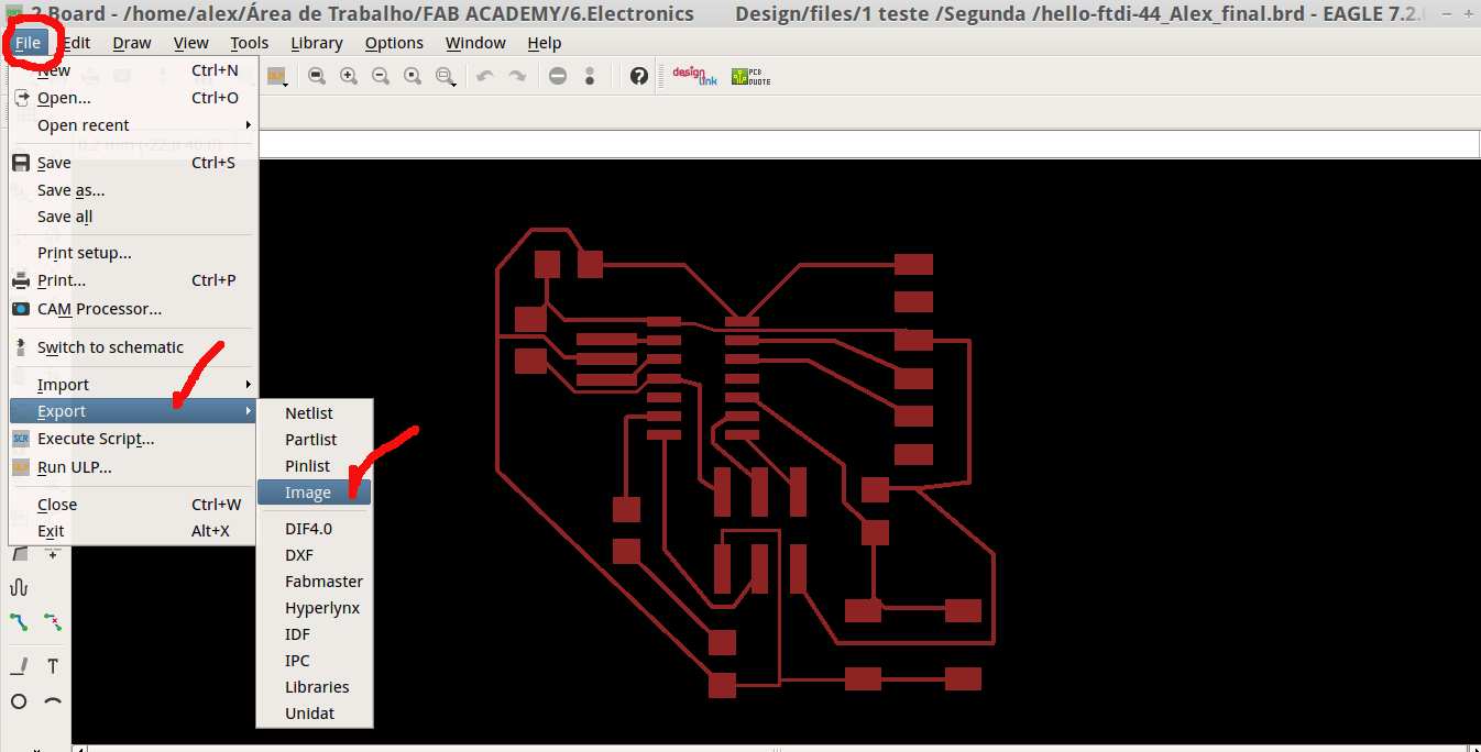
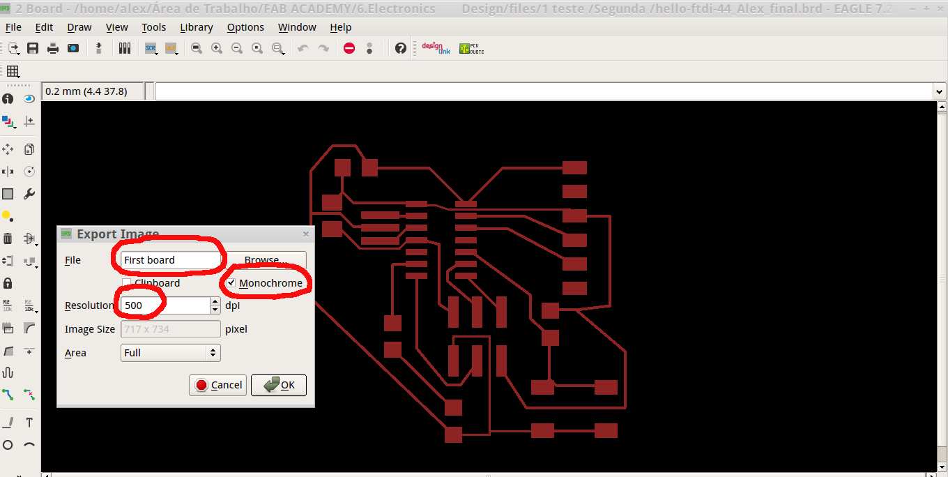
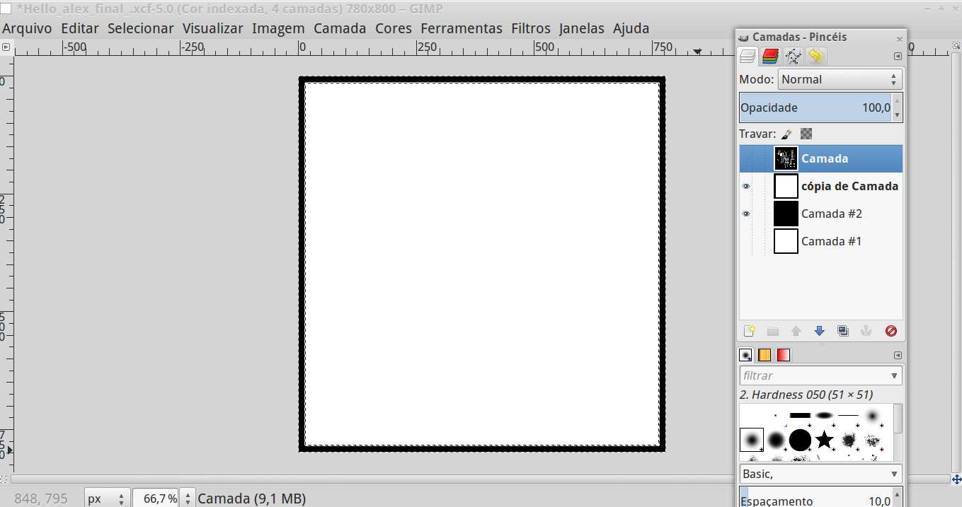
This image file, generated from Eagle, I opened in Gimp to make the outline.
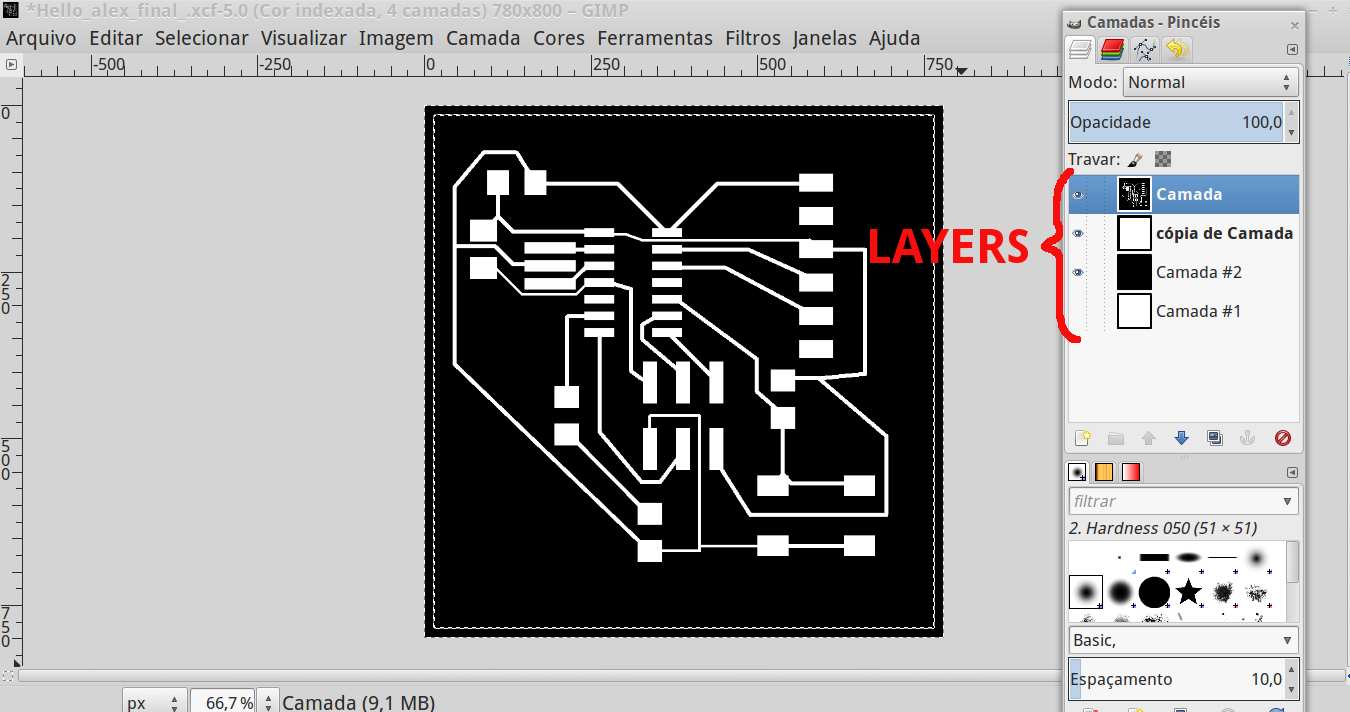
To process it with Fab Modules I followed the same exercise Electronics production .
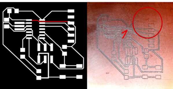
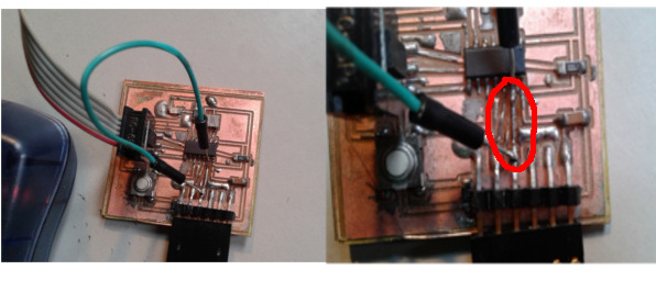
The board problem was a thin wire across the Attiny, the wire was too thin that took off the board (see the red arrow). I did three times changing the parameters to stronger it but all failed and I need to redraw the board. This foto had a base problem too (see the red circle).
I redesign a new board with more attention at the wires do not cross the Attiny. I worked again with 'autorouter' but moving manually the wires to fit the final design.
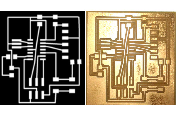
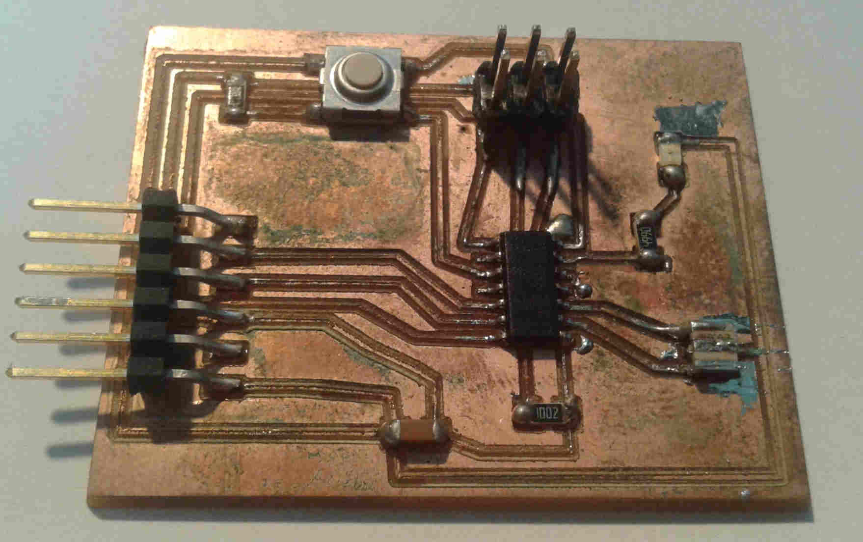
This board passed from fabricating it but not in soldering it.
The board problem was a thin wire that took off the board (again), I tried to fix it with a jumper without sucess.
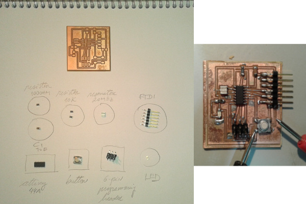
Back to the Eagle, I redesigned the board with more attention about the width wire and spacing them as far as possible. I fabricated and soldered it.
This assignment made me to realize that the Electronic design is really like a project, you need to think about all the problems before to fabricate it.
I have the opportunity to design, fabricate, soldering and do all again to troubleshoot.
hello-ftdi-44.brd file is the board file.
hello-ftdi-44.sch file is the schematic file.