
- Playing with FreeCad
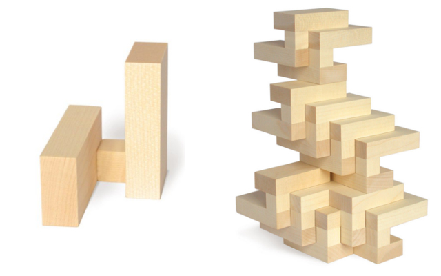
I am very curious about drawing with coding. I'm not a programmer, then I chose to experiment with FreeCAD and OpenSCAD. I worked in two ways, first drawing and after that, coding it. My experiments were inspired by a geometric construction block for children in order to get ideas about my final project. I hope to help the discussion about CAD's drawing ways.
FreeCad is open source CAD open-source and highly customizable, scriptable and extensible and It was started around 2002 by two German engineers, Jürgen Riegel and Werner Mayers.
- First steps with 2D 3D FreeCad - without code
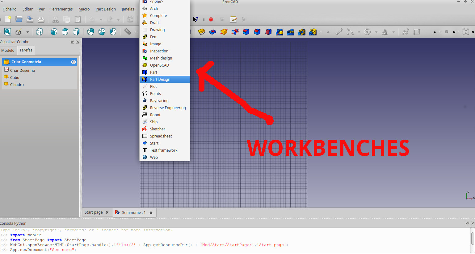
Freecad has some peculiarities, the interfaces or workbenches, can be changed as you need to use the functions, for example, I began with "part design" workbench to begin the 2D drawing.
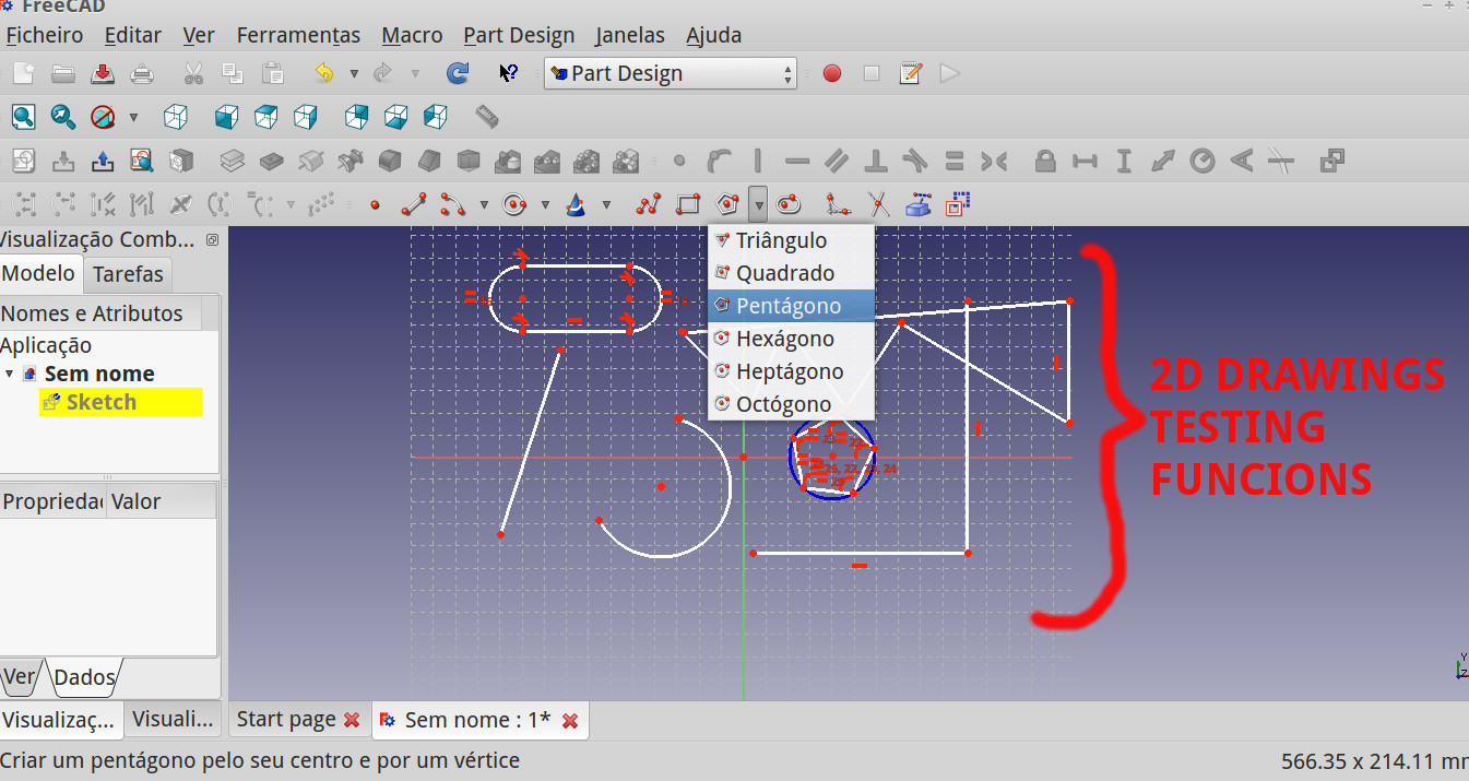
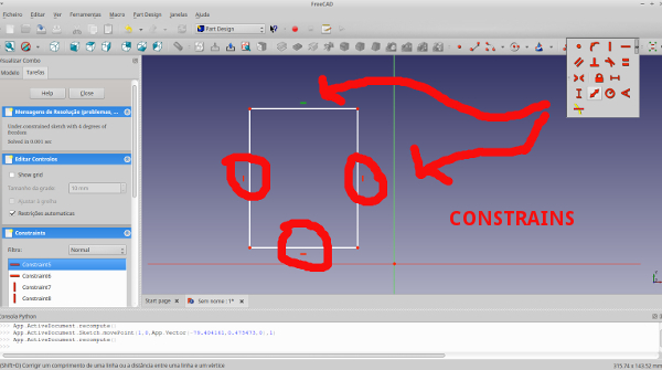
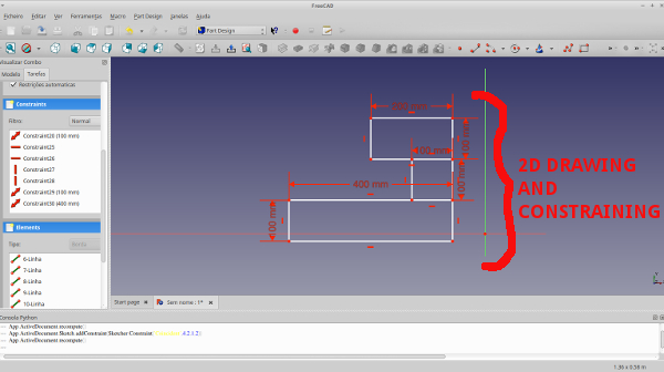
Freecad works "constraining" the object's dimensions. This function is indicated above the object as a red line. In simple words: first you draw and then constrain it.
To extrude the 2D to 3D, I closed the "Sketch"'s task and selected "Pad", and To my surprise all the blocks runned at the same size
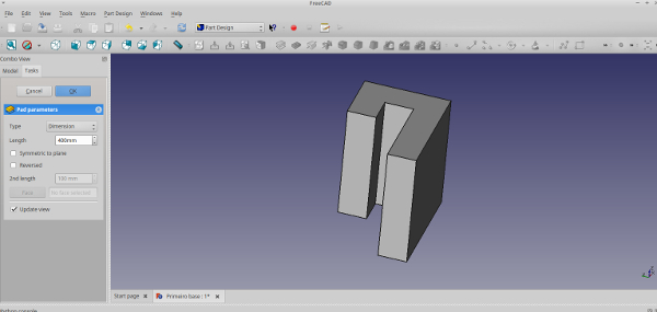
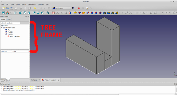
My block is not this way. Then I got that FreeCad works as a "Tree framework" so I needed to redraw every rectangle in a different "Sketch" and then apply the function ("pad") separately.
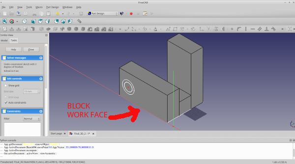
To change the work plane to enable to draw at the block face, I chose the face and selected "Sketch", then one work plane is generated to work in. To do cylinders at the face first I drew circles
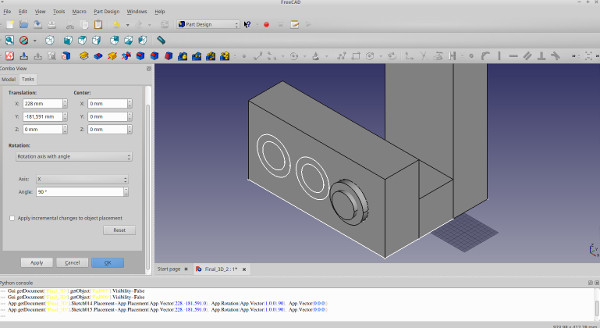
To change the work plane to enable to draw at the block face, I chose the block face and selected "Sketch", then, I drew circles, "pad it" and copy and move it.
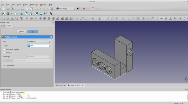
And then, the final exercice drawing 2D and 3D with Freecad without coding.
To generate the .dxf files, to my surprise Freecad is not able to export 3D to .dxf. Searching about I find out that:
"3D DXF relies on ACIS, a proprietary geometric kernel, to share data. As with all proprietary kernels, ACIS is undocumented, and In short, exporting to 3D DXF is not possible. FreeCAD can export to open 3D CAD exchange formats like STEP and IGES. Those formats are supported by almost all major CAD packages. If your machinist's software cannot open such files, well you're out of luck."
And that Freecad can export many extentions and 2D .dxf lines. Then to generate .dxf I exported in.STEP to Rhinoceros and exported to .dxf.
- Coding 2D and 3D with FreeCad
Freecad has a console that it possible to script in Python and execute. Very fast it is fascinating how a code line transform in virtual objects.
For example, if you copy and paste this code in the console:
import Part
          from FreeCAD import Vector
          #import modules
          a = Part.makeBox(10,20,40,Vector(1,0,0))
          b = Part.makeBox(10,10,10,Vector(11,0,0))
          c = Part.makeBox(10,40,20,Vector(21,0,0))
          d = a.fuse(b)
          e = d.fuse(c)
          Part.show(e)
          #Drawing the 3D block and union and showing it.
You will see this image:
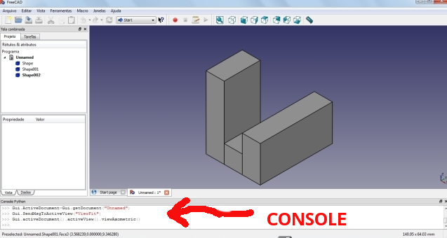
This was my code from my 2013 assignment and below I will explore more in drawing 2D - 3D. The next code:
from FreeCAD import Vector
from FreeCAD import Base
import Part
#import modules
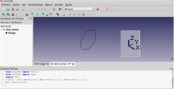
circle = Part.makeCircle(5,Base.Vector(0,0,0),Base.Vector(1,0,0))
Part.show(circle)
#Drawing the circle and positioning it.
Made me discover how to draw/code a 2D circle from parameters as radius, coordinates and direction. If you copy this code and paste in the Freecad console you wll see this:
The next step is put 2D circles at and position it at the block face. Studying and testing, I did this code:
          #Drawing 2D circles and position it.

          from FreeCAD import Base
          from FreeCAD import Vector
          import Part
          #import modules

          box1 = Part.makeBox(10,20,40,Vector(1,0,0))
          box2 = Part.makeBox(10,10,10,Vector(11,0,0))
          box3 = Part.makeBox(10,40,20,Vector(21,0,0))
          union = box1.fuse(box2)
          final_union = union.fuse(box3)
          Part.show(final_union)
          #Drawing the 3D block and union and showing it.

          circle1 = Part.makeCircle(5, Base.Vector(11,10,34),Base.Vector(1,0,0))
          Part.show(circle1)
          circle2 = Part.makeCircle(5, Base.Vector(31,5,10),Base.Vector(1,0,0))
          Part.show(circle2)
          circle3 = Part.makeCircle(5, Base.Vector(31,20,10),Base.Vector(1,0,0))
          Part.show(circle3)
          circle4 = Part.makeCircle(5, Base.Vector(31,35,10),Base.Vector(1,0,0))
          Part.show(circle4)
          #Drawing the circle and positioning it.
If you copy and paste this code, you will see this:
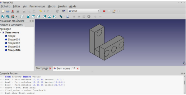
The next is to do basic boolean operations and transformations 2D to 3D.
To to this I worked with several tutorials and spend hours in organize and apply it. I would highlight some tutorials as wiki/FreeCAD/Python that have lots of examples, this topological study and this piston + conrod sketch-based animation that is very interesting to see the power of FreeCAD/Python. In Portuguese this Prof. Tavares blog. is very interesting
Then, the final code:
          #Extrude (2D to 3D) and do basics boolean operations.

          from FreeCAD import Base
          from FreeCAD import Vector
          import Draft
          import Part
          #import modules

          box1 = Part.makeBox(10,20,40,Vector(1,0,0))
          box2 = Part.makeBox(10,10,10,Vector(11,0,0))
          box3 = Part.makeBox(10,40,20,Vector(21,0,0))
          union = box1.fuse(box2)
          final_union = union.fuse(box3)
          #Drawing the 3D block and union it

          circle1 = Part.makeCircle(2,Base.Vector(5,0,20),Base.Vector(0,1,0))
          wire = Part.Wire(circle1)
          face = Part.Face(wire)
          extr = face.extrude(FreeCAD.Vector(0,-3,0))
          #Drawing and transforming the circle: wire / face / extrude.

          circle2 = Part.makeCircle(4,Base.Vector(5,0,20),Base.Vector(0,1,0))
          wire2 = Part.Wire(circle2)
          face2 = Part.Face(wire2)
          extr2 = face2.extrude(FreeCAD.Vector(0,-2,0))
          #Drawing and transforming the circle: wire / face / extrude.

          circle3 = Part.makeCircle(2, Base.Vector(31,5,10),Base.Vector(1,0,0))
          wire3 = Part.Wire(circle3)
          face3 = Part.Face(wire3)
          extr3 = face3.extrude(FreeCAD.Vector(3,0,0))
          #Drawing and transforming the circle: wire / face / extrude.

          circle4 = Part.makeCircle(2, Base.Vector(31,20,10),Base.Vector(1,0,0))
          wire4 = Part.Wire(circle4)
          face4 = Part.Face(wire4)
          extr4 = face4.extrude(FreeCAD.Vector(3,0,0))
          #Drawing and transforming the circle: wire / face / extrude.

          circle5 = Part.makeCircle(2, Base.Vector(31,35,10),Base.Vector(1,0,0))
          wire5 = Part.Wire(circle5)
          face5 = Part.Face(wire5)
          extr5 = face5.extrude(FreeCAD.Vector(3,0,0))
          #Drawing and transforming the circle: wire / face / extrude.
          circle6 = Part.makeCircle(4, Base.Vector(31,5,10),Base.Vector(1,0,0))
          wire6 = Part.Wire(circle6)
          face6 = Part.Face(wire6)
          extr6 = face6.extrude(FreeCAD.Vector(2,0,0))
          #Drawing and transforming the circle: wire / face / extrude.

          circle7 = Part.makeCircle(4, Base.Vector(31,20,10),Base.Vector(1,0,0))
          wire7 = Part.Wire(circle7)
          face7 = Part.Face(wire7)
          extr7 = face7.extrude(FreeCAD.Vector(2,0,0))
          #Drawing and transforming the circle: wire / face / extrude.

          circle8 = Part.makeCircle(4, Base.Vector(31,35,10),Base.Vector(1,0,0))
          wire8 = Part.Wire(circle8)
          face8 = Part.Face(wire8)
          extr8 = face8.extrude(FreeCAD.Vector(2,0,0))
          #Drawing and transforming the circle: wire / face / extrude.

          Part.show(final_union)
          Part.show(face)
          Part.show(extr)
          Part.show(extr2)
          Part.show(extr3)
          Part.show(extr4)
          Part.show(extr5)
          Part.show(extr6)
          Part.show(extr7)
          Part.show(extr8)
          #Showing the result.
And the result
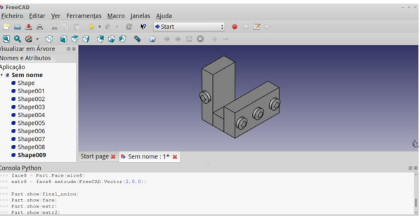
Now,I will work with other software to compare it.
- Coding 2D and 3D with OpenSCAD
OpenSCAD is a free software has been written by Clifford Wolf and Marius Kintel. With the syntax more friendly than FreeCAD/Python, with OpenSCAD was more fast to the exercise.To begin with OpenSCAD I suggest see this wiki and this beginners tutorial
I take again my exercice to complete the assigment and doing more operations.
This is my first code:
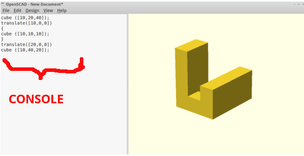
          //Drawing and union the blocks.
          Union () {
          	cube ([10,20,40]);
          	translate([10,0,0])
          	{
          		cube ([10,10,10]);
          	}
          	translate([20,0,0])
          	cube ([10,40,20]);
          	}
If you copy and past at Openscad console you will generate this:
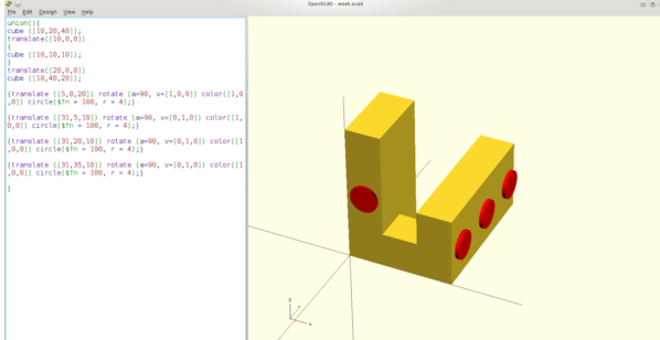
It is possible to work with 2D drawing in OPenSCAD, as related by this tutorial OpenSCAD Wiki/2DPrimitives
My objective is to draw 2D circles and positioning it at the face block, as I did with Freecad.In Openscad, the 2D objects are rendered with 1 thickness.
Then, this code:
          //Drawing and union the blocks.
          union(){
          cube ([10,20,40]);
          translate([10,0,0])
          {
          cube ([10,10,10]);
          }
          translate([20,0,0])
          cube ([10,40,20]);

          //Drawing and positioning the 2D circles.
          {translate ([5,0,20]) rotate (a=90, v=[1,0,0])
          color([1,0,0]) circle($fn = 100,
           r = 4);}

          {translate ([31,5,10]) rotate (a=90, v=[0,1,0])
          color([1,0,0]) circle($fn = 100,
           r = 4);}

          {translate ([31,20,10]) rotate (a=90, v=[0,1,0])
          color([1,0,0]) circle($fn = 100, r = 4);}

          {translate ([31,35,10]) rotate (a=90, v=[0,1,0])
          color([1,0,0]) circle($fn = 100, r = 4);}

          }
Will generate this:
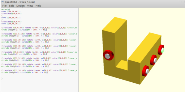
Now, we will extrude through code, see that I included "linear_extrude (height=2)" and adapted the code:
          //Drawing and union the blocks.
          union(){
          cube ([10,20,40]);
          translate([10,0,0])
          {
          cube ([10,10,10]);
          }
          translate([20,0,0])
          cube ([10,40,20]);

          //Extruding 2D circles.
          {translate ([5,0,20]) rotate (a=90, v=[1,0,0]) color([1,0,0]) linear_extrude
          	 (height=2) circle($fn = 100, r = 4);}
          {translate ([31,5,10]) rotate (a=90, v=[0,1,0]) color([1,0,0]) linear_extrude
          	 (height=2)  circle($fn = 100, r = 4);}
          {translate ([31,20,10]) rotate (a=90, v=[0,1,0]) color([1,0,0]) linear_extrude
          	 (height=2) circle($fn = 100, r = 4);}
          {translate ([31,35,10]) rotate (a=90, v=[0,1,0]) color([1,0,0]) linear_extrude
          	 (height=2) circle($fn = 100, r = 4);}
          {translate ([5,0,20]) rotate (a=90, v=[1,0,0]) color([1,1,1]) linear_extrude
          	 (height=3) circle($fn = 100, r = 2);}
          {translate ([31,5,10]) rotate (a=90, v=[0,1,0]) color([1,1,1]) linear_extrude
          	 (height=3)  circle($fn = 100, r = 2);}
          {translate ([31,20,10]) rotate (a=90, v=[0,1,0]) color([1,1,1]) linear_extrude
          	 (height=3) circle($fn = 100, r = 2);}
          {translate ([31,35,10]) rotate (a=90, v=[0,1,0]) color([1,11]) linear_extrude
          	 (height=3) circle($fn = 100, r = 2);}
          }
And the result:
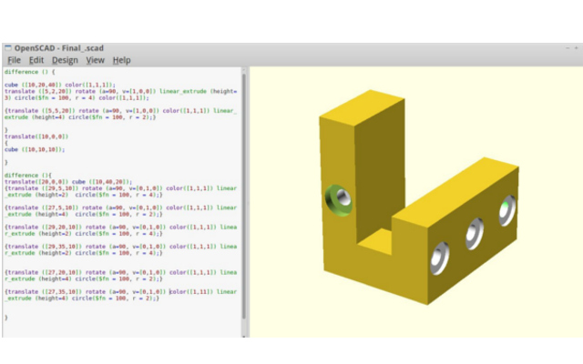
After extrusion I did holes in the block, an extra exercice.
          //Drawing, union and difference (cutting) the blocks.
          	difference () {
          	cube ([10,20,40]) color([1,1,1]);
          	translate ([5,2,20]) rotate (a=90, v=[1,0,0]) linear_extrude (height=3)
          	circle($fn = 100, r = 4) color([1,1,1]);
          	{translate ([5,5,20]) rotate (a=90, v=[1,0,0]) color([1,1,1]) linear_extrude
          	(height=4) circle($fn = 100, r = 2);}
          	}
          	translate([10,0,0])
          	{
          	cube ([10,10,10]);
          	}
          //Drawing, union and difference (cutting) the blocks.
          	difference (){
          	translate([20,0,0]) cube ([10,40,20]);
          	{translate ([29,5,10]) rotate (a=90, v=[0,1,0]) color([1,1,1])
          		linear_extrude (height=2)  circle($fn = 100, r = 4);}
          	{translate ([27,5,10]) rotate (a=90, v=[0,1,0]) color([1,1,1])
          		 linear_extrude (height=4)  circle($fn = 100, r = 2);}
          	{translate ([29,20,10]) rotate (a=90, v=[0,1,0]) color([1,1,1])
          		linear_extrude (height=2) circle($fn = 100, r = 4);}
          	{translate ([29,35,10]) rotate (a=90, v=[0,1,0]) color([1,1,1])
          		linear_extrude (height=2) circle($fn = 100, r = 4);}
          	{translate ([27,20,10]) rotate (a=90, v=[0,1,0]) color([1,1,1])
          		linear_extrude (height=4) circle($fn = 100, r = 2);}
          	{translate ([27,35,10]) rotate (a=90, v=[0,1,0]) color([1,11])
          		linear_extrude (height=4) circle($fn = 100, r = 2);}
          	}
And the result:
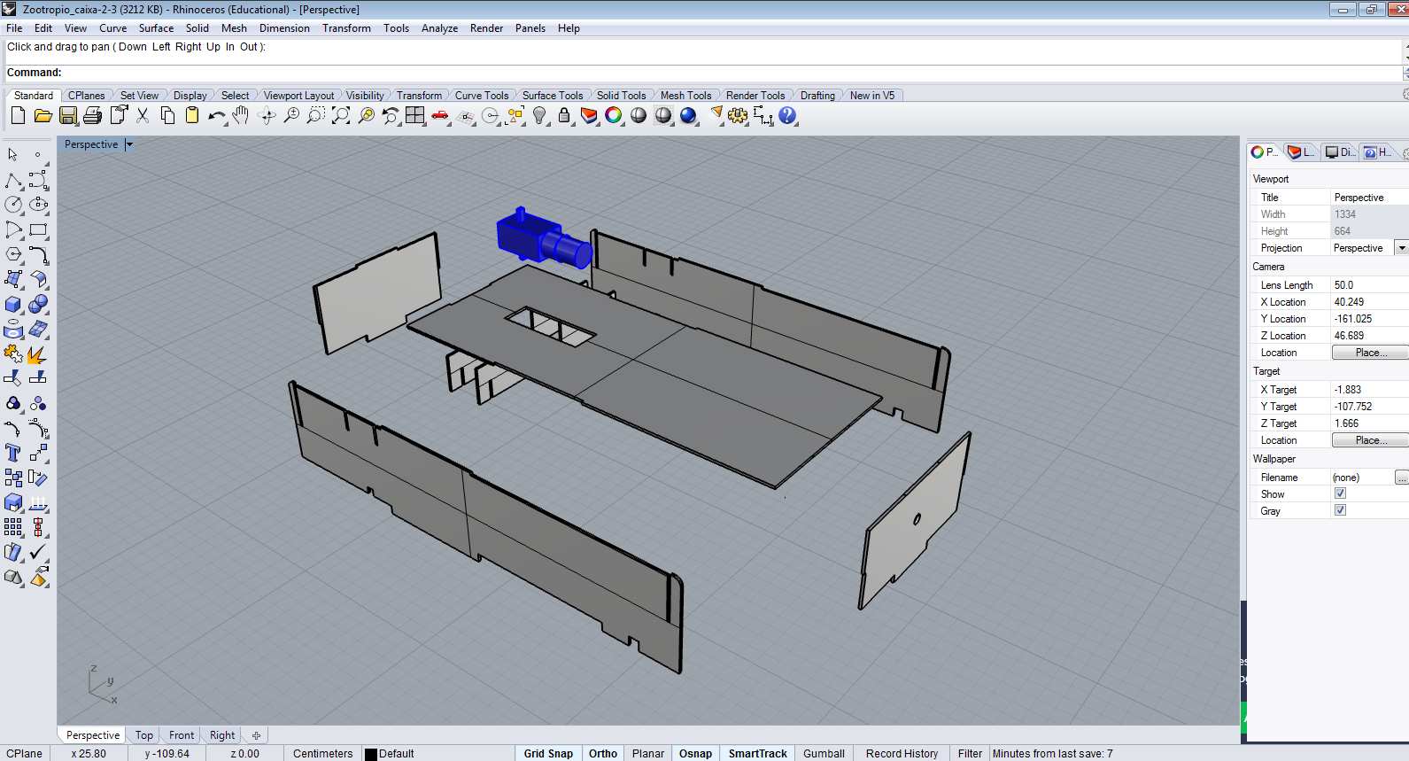
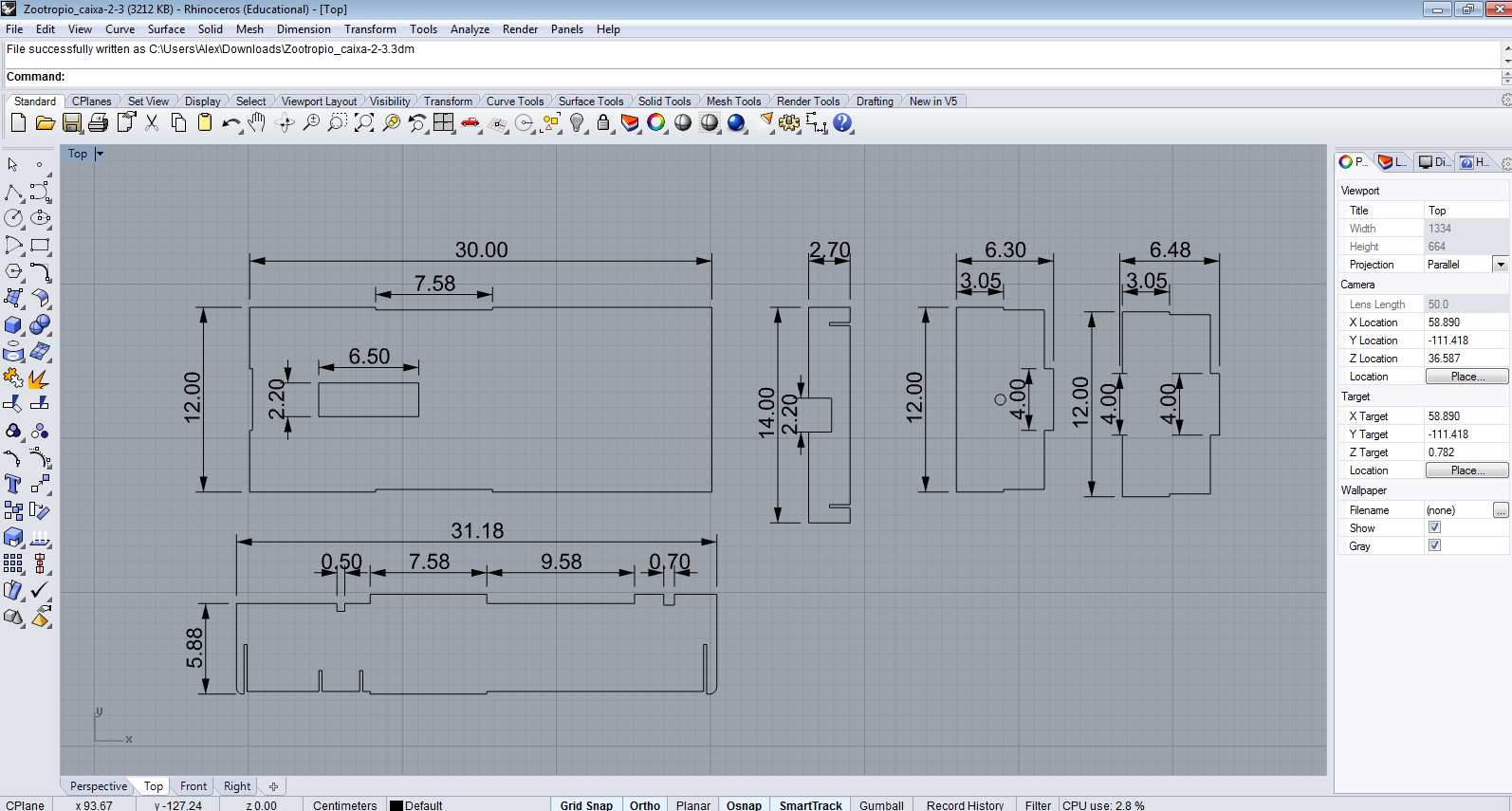
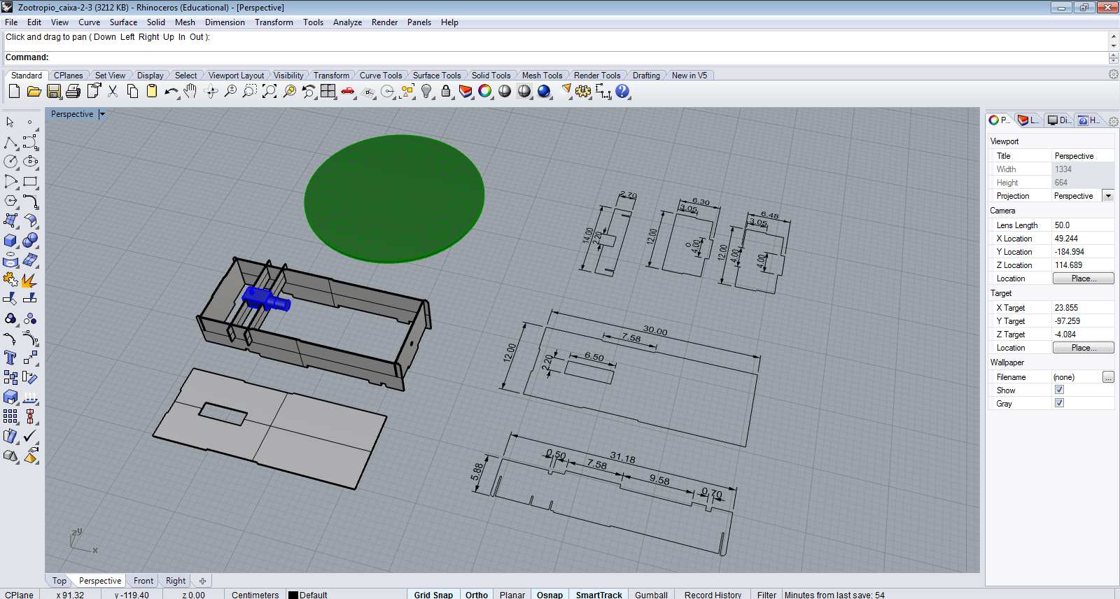
-Rhinoceros 3D and my final project
To final project with Juliana Henno, the Fab Zootrope, I designed the motor box proposal. I worked with Rhinoceros 3D. This software is very easy to use and render the 3D. Basically I used rectangles shapes, booleanas and extrude it.
- Conclusions
- Freecad as a Cad interface:It is easy to use?
FreeCad for me was at same time hard and very interesting because it was possible to program it, has lots of tutorials and is free. I feel that in order to code with Python and FreeCad the non programmers need patience and persistence.
Freecad, has a “harder” interface when compared to other CAD softwares (like the ones I used before: Rhinoceros and Autocad).
- Freecad and Openscad: CAD and coding
FreeCAD/Phyton and OpenSCAD differs itselves in many ways, FreeCAD open possibilities using Python, a well known language. The OpenSCAD uses its own codes and so, is very simple, fast and direct.
Maybe, Freecad could be able to do complex designs than Openscad, and one more vantage is that Freecad can be used without coding.
To to this drawing (block) using common CAD's softwares is very simple, because all the commands are automated, but to do it by code demands attention, knowledge of math and logical thinking. One moment I felt like I had to stop, hand draw and calculate before scripting, so I think the work with codes include more abilities than just “operate software commands”.
- Rhinoceros 3D CAD design
Rhino to me is a very friendly CAD, very easy to use but is a proprietary software and cannot be installed in Linux OS.