
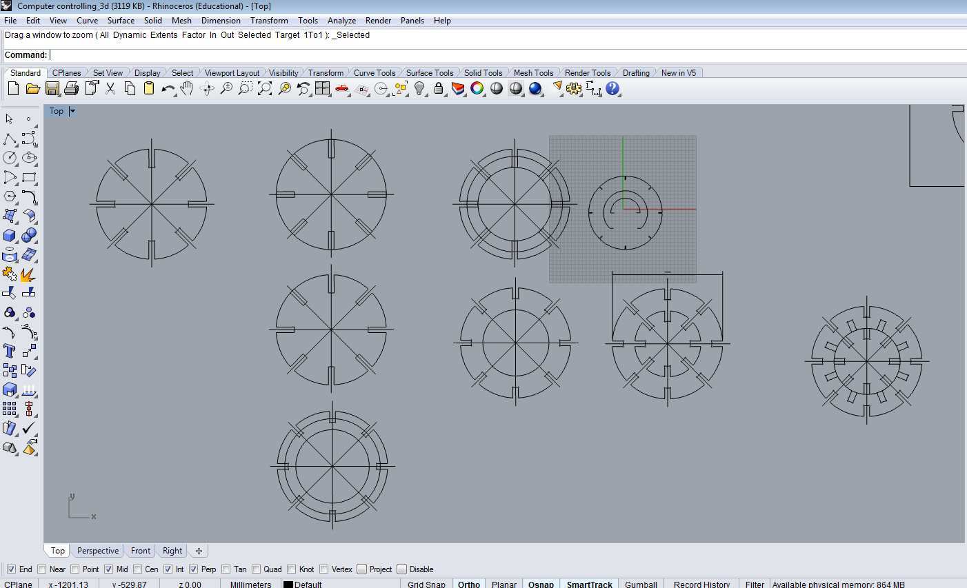
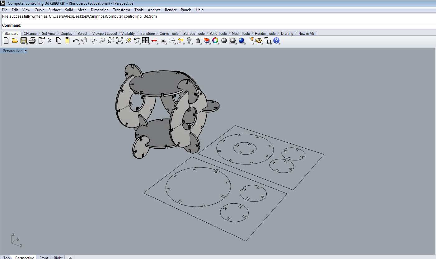
First I review my parametric Freecad design and to my surprise take me so much time and work to stabilize the design. Freecad is so interesting software and be able to work with complex designs as the Brazil´s Wiki house´s made by Yorik Freecad templates. but now to my academy and my little time, I had to choose go back to Rhinoceros 3D that I able to operate more fast.
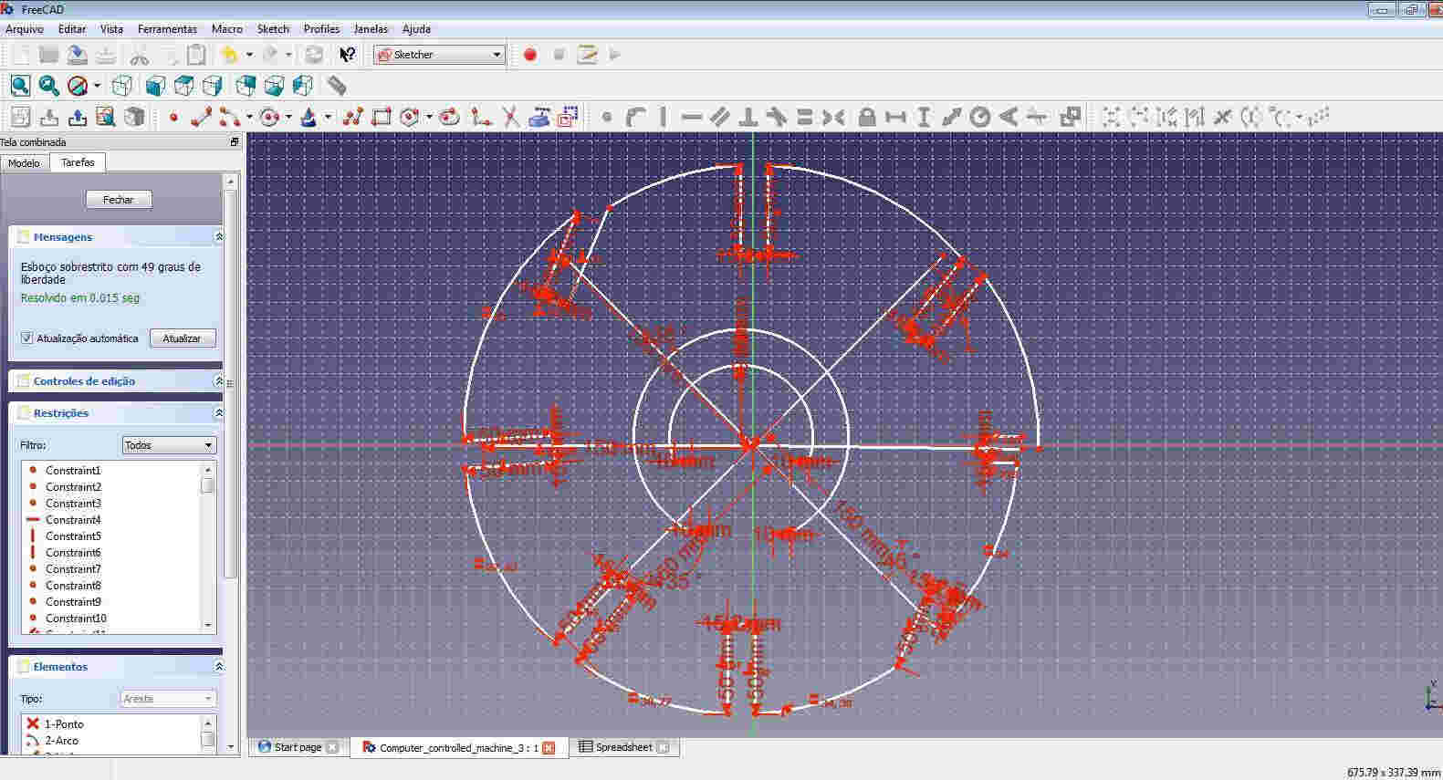
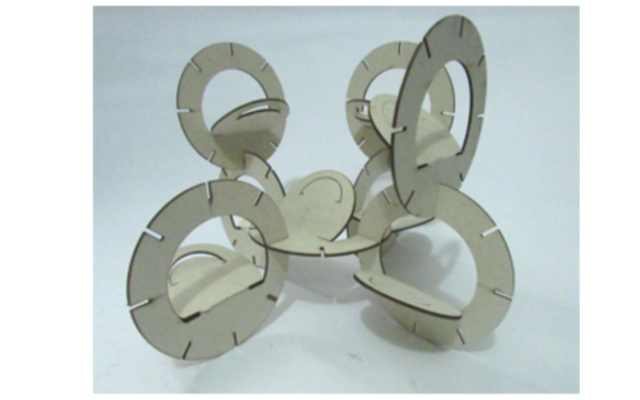
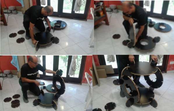
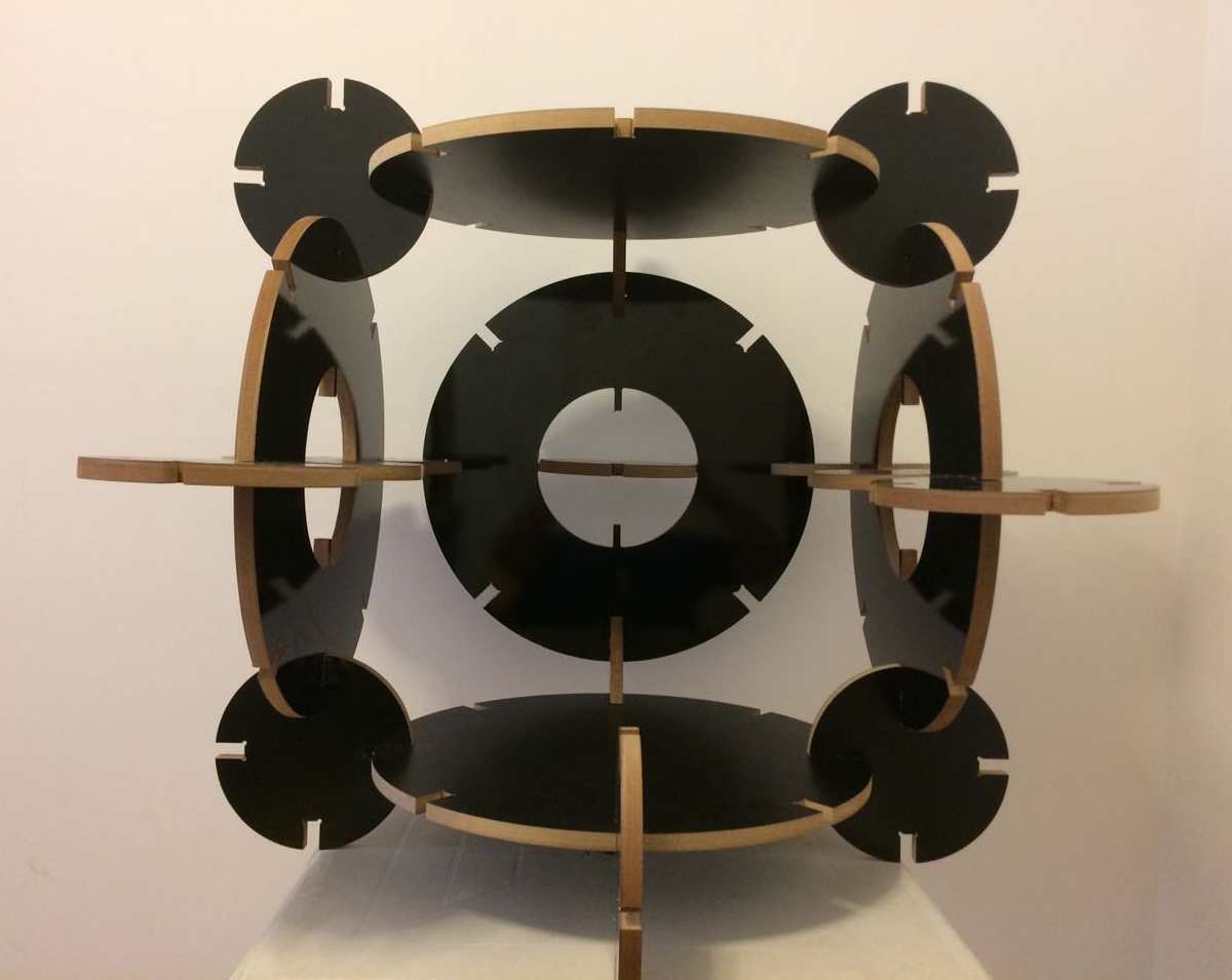
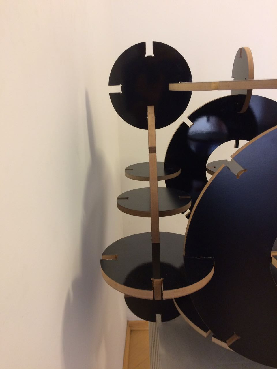
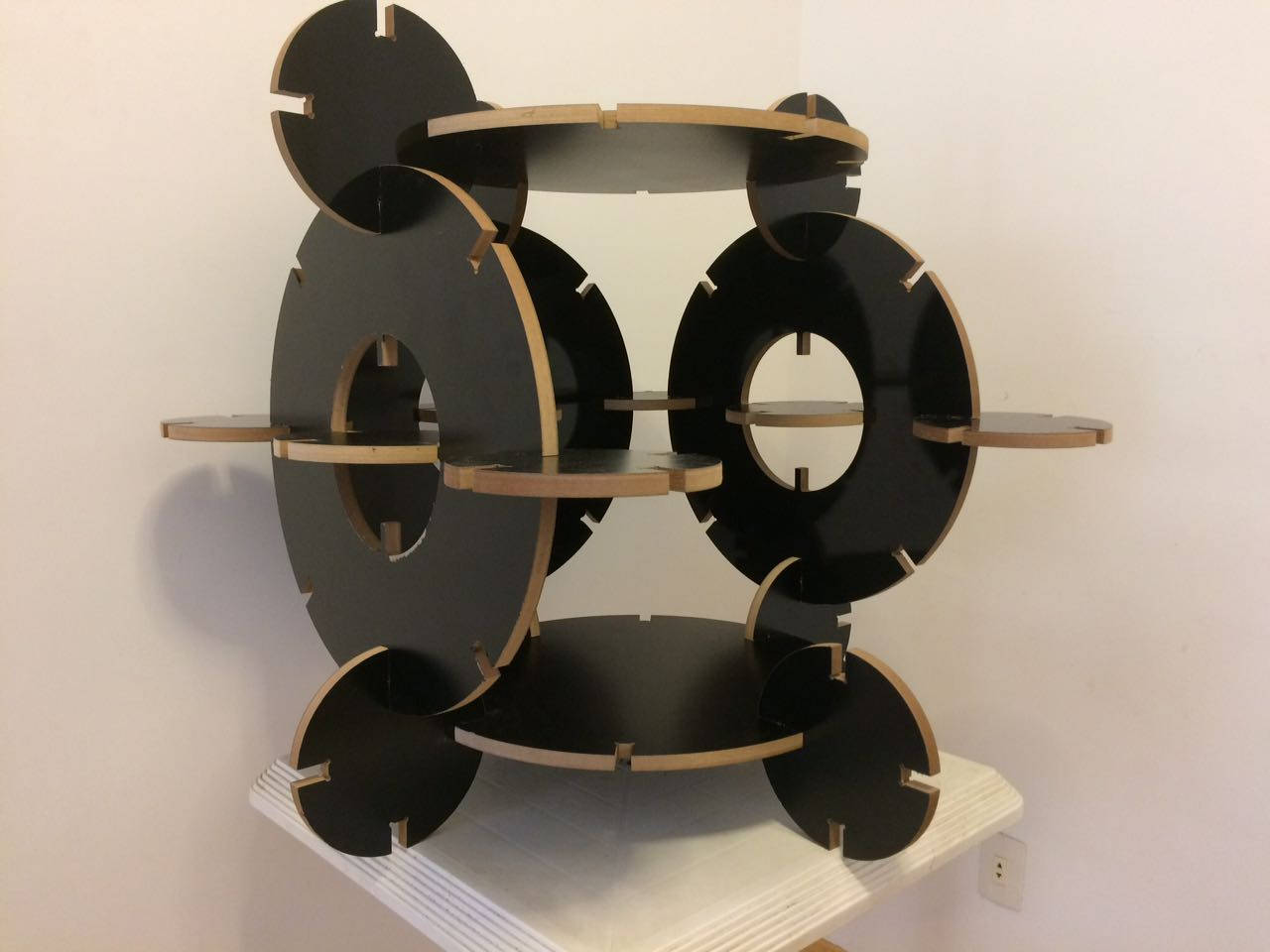
The assignment core is to redraw to do the same, or similar structure as I did in computer controlled cutting.
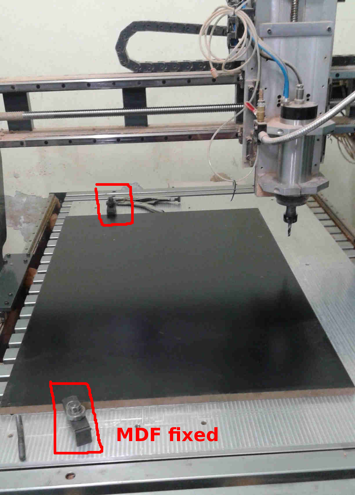
- The CNC Machine
I used a CNC milling machine (TFX CNC 1.200 x 700mm) from a Rede Fab Lab Brasil´s partner: CNC Montion company.

- The Material
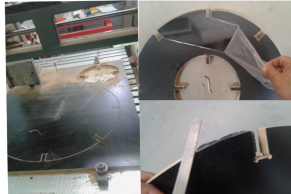
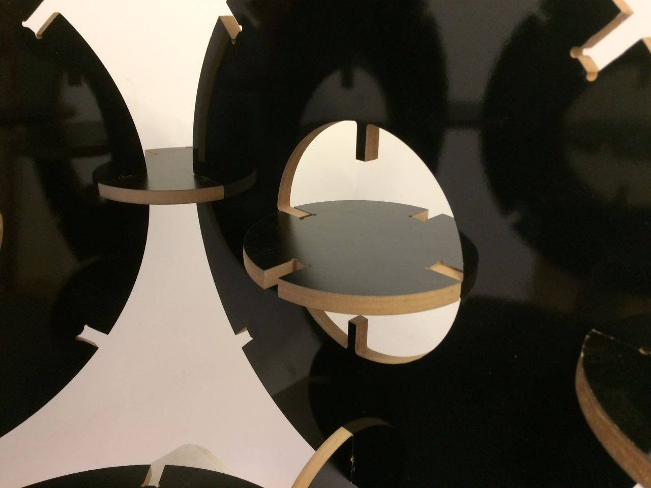
I chose MDF that is a easy material to work with CNC, but MDF "can be dangerous to use because it contains a substance called urea formaldehyde, which may be released from the material through cutting and sanding." More information see MDF
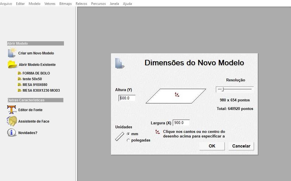
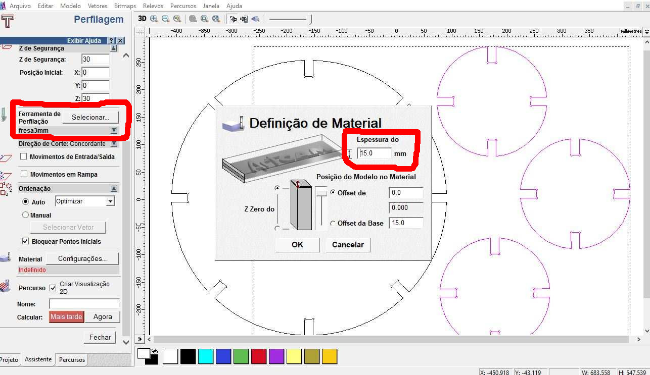
Material dimensions - 15 mm x 900 x 600 - Thickness x Length x Width (mm) Black MDF color.
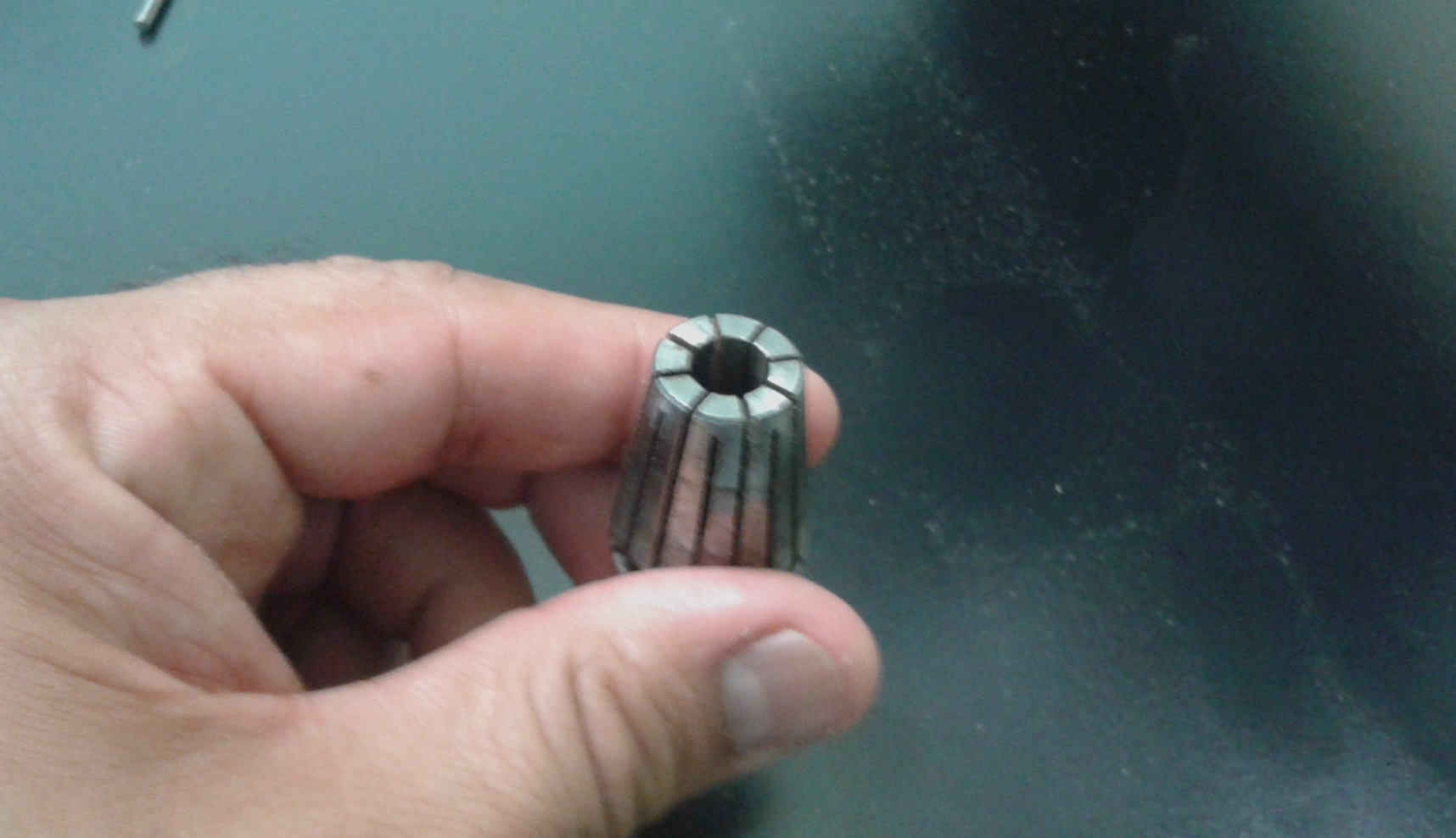
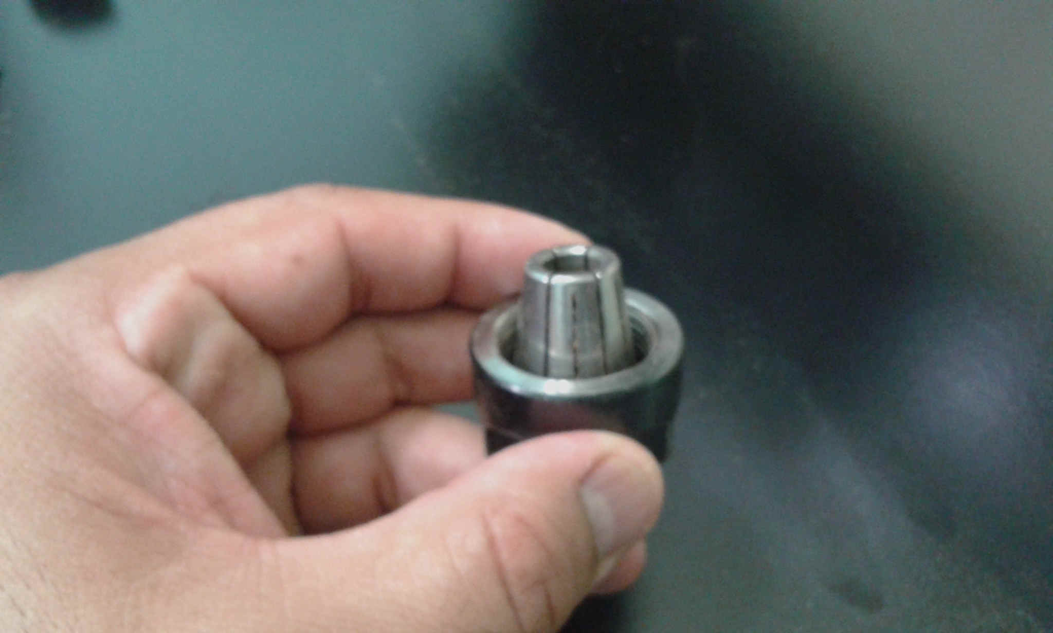
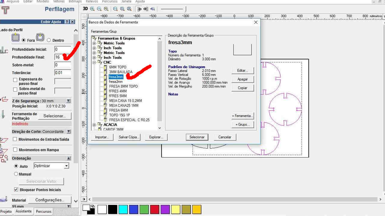
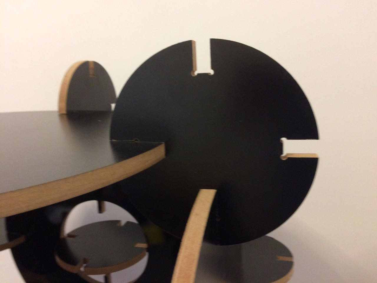
- The end mill
I used a 3mm diameter endmill.
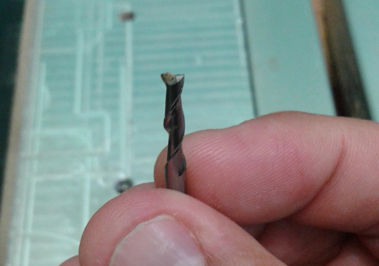
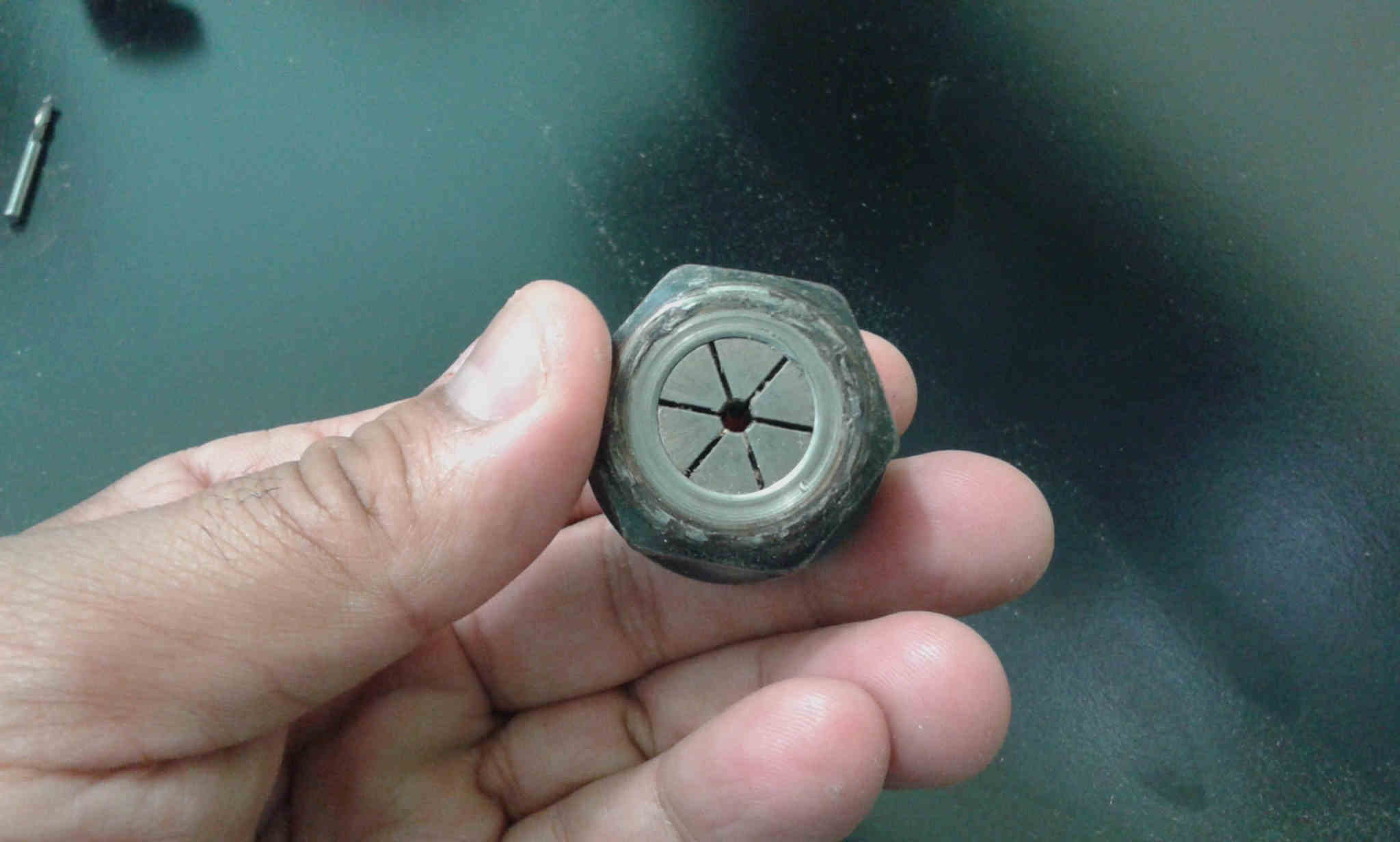
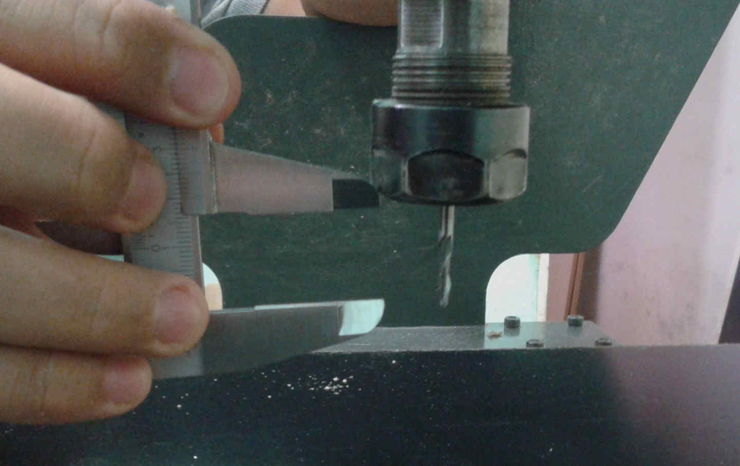
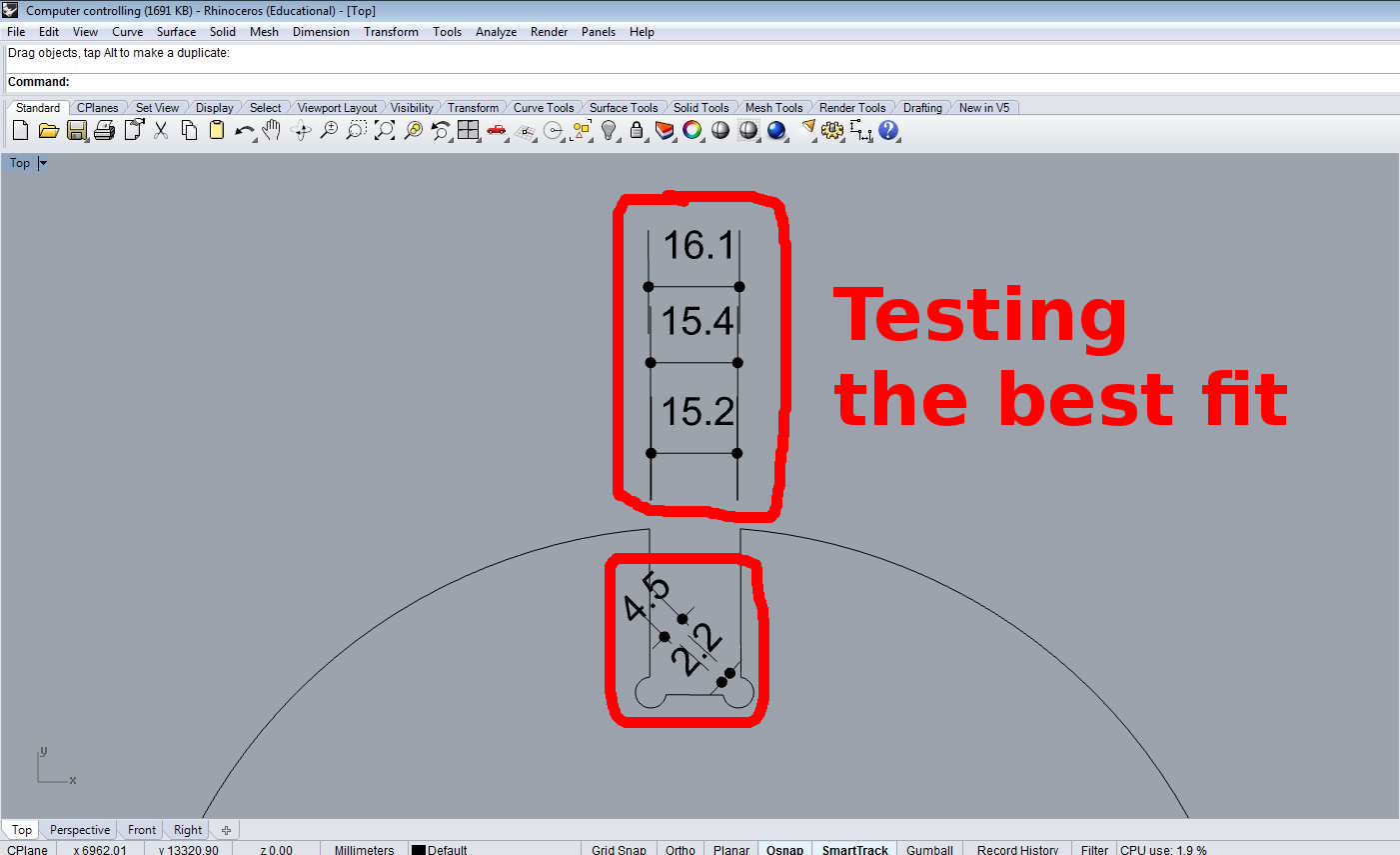
I adapted to the mill dimensions.
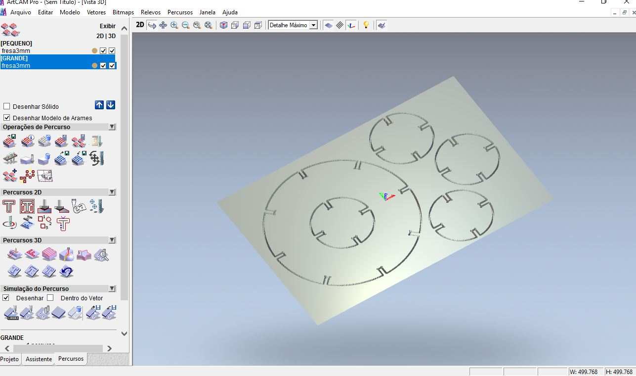
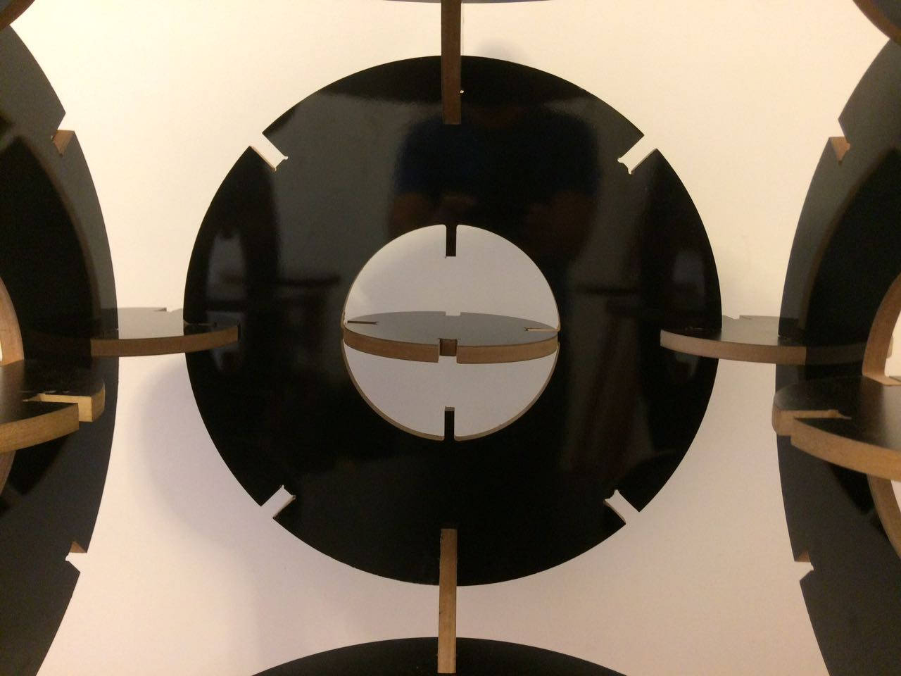
This fabricating workflow made me improve the CAM parameters as mill steps and the "dog bone" that will be explaned below.
- The workflow
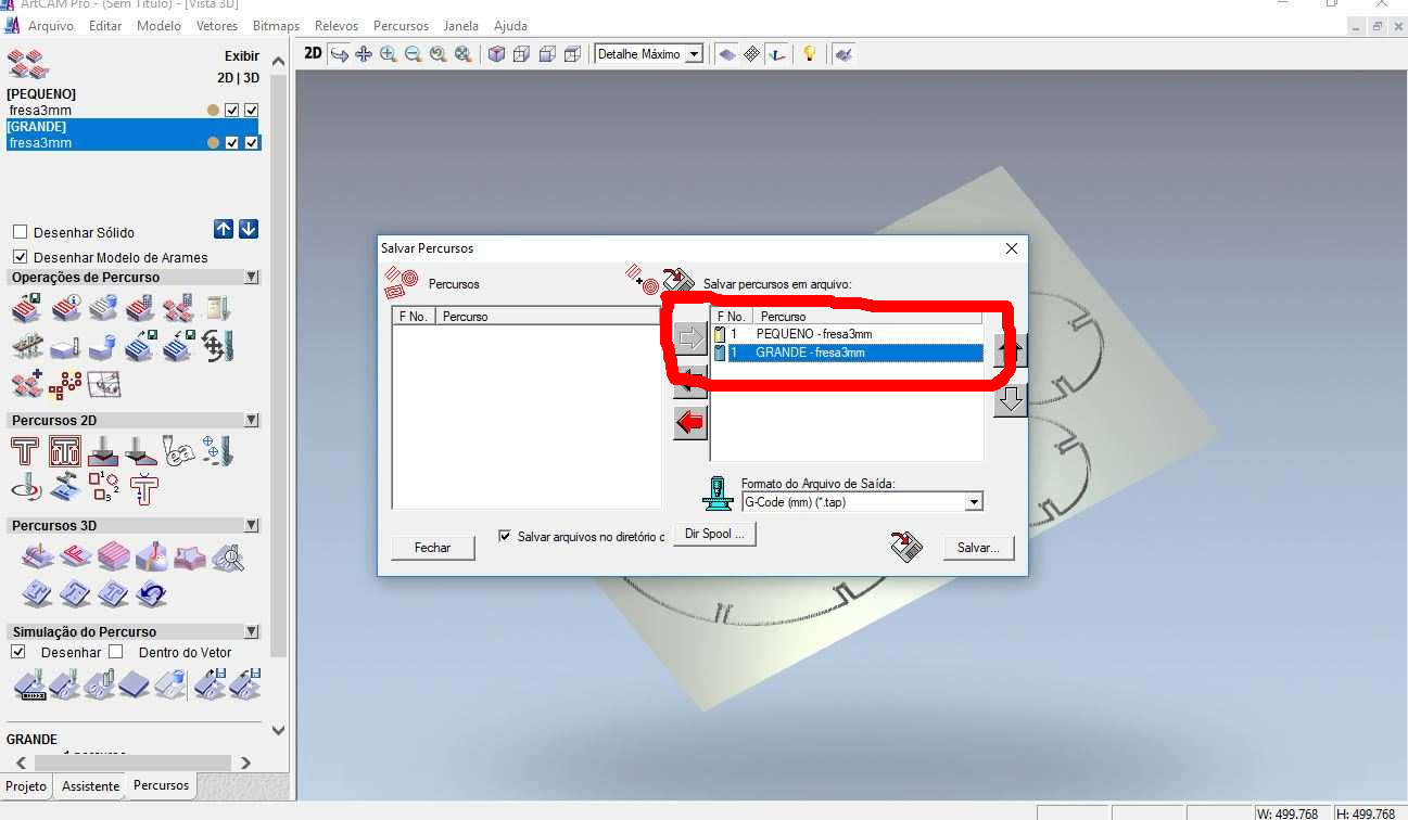
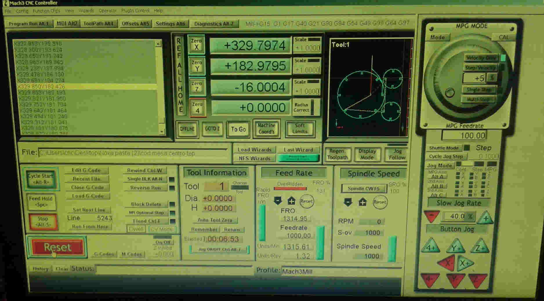
Softwares CAM: ARTCAM, MARCH 3 and CAD Rhinoceros 3D.
This assignment made me to reflect about the Laser and Milling machines. In both, the fabrication process should be thought since the CAD design. It´s obvious, but the main differenceis how the cutting happens. The CAD CAM Laser/Milling method can be similar, but the Laser can be worked with light materials and the Milling machine with more thickness/hard materials as wood. While Laser cut can be more "clean" in a way that it "burns" the material, the Milling machine produces more leavings in the process. One interesting use to Milling cutter is the z axis that is possible to sculp material as I will show below.
Softwares CAM: Vcarv , CUT 3D and MARCH 3 and CAD Rhinoceros 3D/Grasshopper.
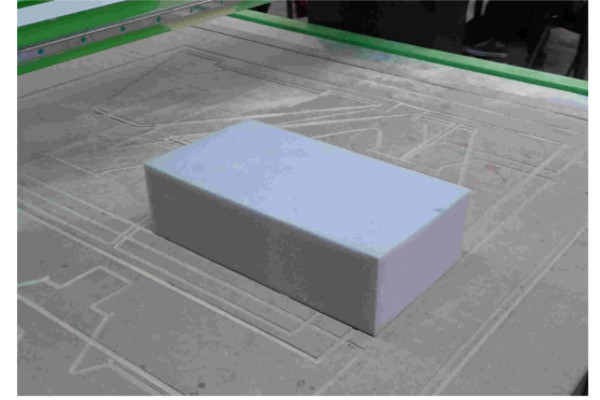
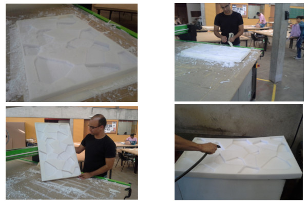
Inspiration:"Quave Inman – Molds For Slumping Glass" from Anna Kaziunas blogFor this assignment I worked with high density polyurethane foam and a milling machine. The foam I that used was D-46 specification in Brazil, that means the foam density. The material is visually similar as this image
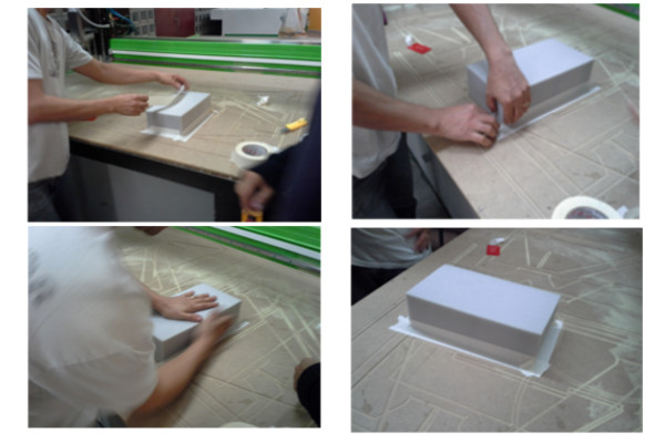
The materials used:
The result was not satisfactory when using the rounded milling cutter so
I changed it to a 6 mm diameter flat bottomed mill in order to do the
final piece.
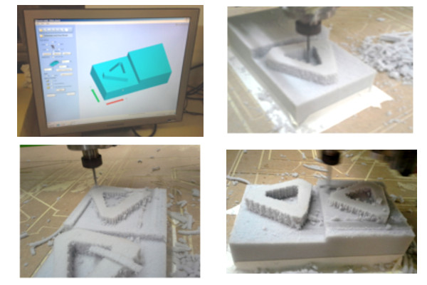
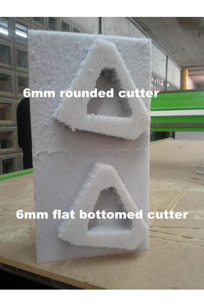
Here is a link that have further explains about the differences between the flat and rounded milling cutter.And here the is the foam milling video.
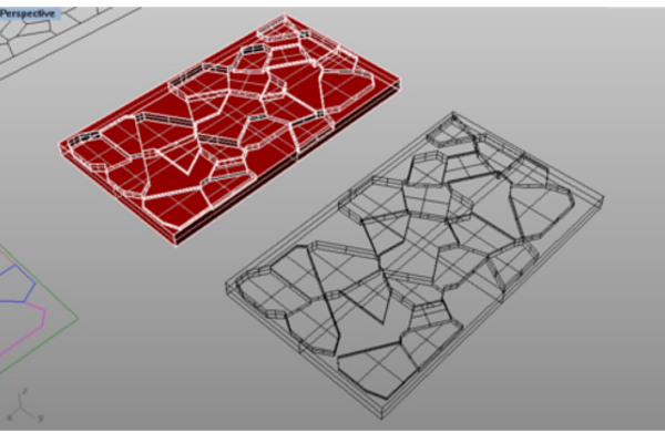
I drew a simple Voronoi pattern with Grasshopper and changed the heights
randomly to create a topography to be milled in a high density polyurethane
foam (875mmx500mmx45mm).
The materials for the second experiment:
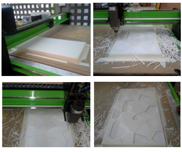
Video about the 3D topography being milled:
Assignment 08 Foam cutting from Alex Angelo on Vimeo.
One problem was when the material whirled around the milling cutter, I solved this problem by pressing a stick of wood against the material stuck on the milling cutter. So it´s important to keep the surface clean during the milling process.
Video:
Assignment 08 Foam twirl from Alex Angelo on Vimeo.
To achieve a better result I created a second GCode that informed the machine to mill only the inside edges of the topography shapes.
Videos:
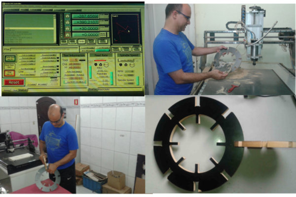
The result
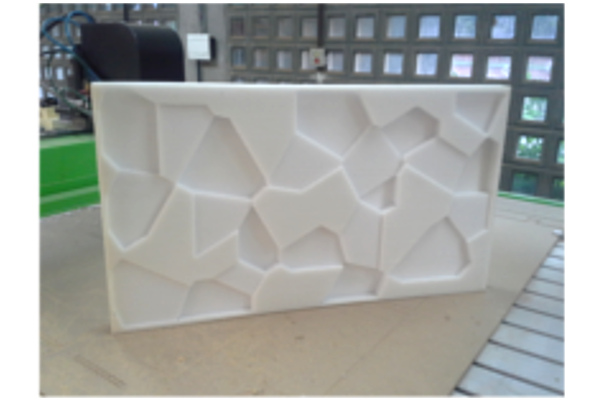
For this assignment I had the opportunity to test different materials in the CNC Milling machine. Because the high density polyurethane foam was never tested in our lab it took me some time to find a better mill to achieve a better finishing for my object. After finding the best mill among the ones we had in our lab I tested milling a new Gcode to refine the edges of the milled surface. I intend to work further in this idea of foam flooring mat in order to adapt this idea for a game in which the kids can explore the geometrical shapes and learn while train their motor skills . The experiment detailed above would work like a module that would be fitted in other modules in order to create a larger area to play.