
Task completed: design, produce, solder and test our microcontroller boards, [ see my Electronics_Design ] testing output device, [ see my Output_devices,] 3D modelling and print the objects to be rotated, [see my 3D_printing. ] laser cut and assemble the parts of the container. [ see my Computer-aided_Design and computer-controlled_cutting ]
Tasks remaining: refine the velocity of the rotation, testing other motors, placing extra LED array boards to increase the strobe effect, try the network/communications boards [see my network/communications ].
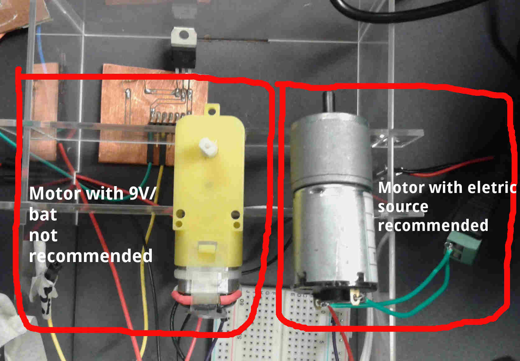
I have a problem with the motor and its regulation of the platform, we used some motors but not pay attentions to the current, we burn one motor ( 6V) and decided to use 9V Batteries with low current, the motor run but decrease rapidly. Then I changed the motor with eletric source: 5V/330 RPM
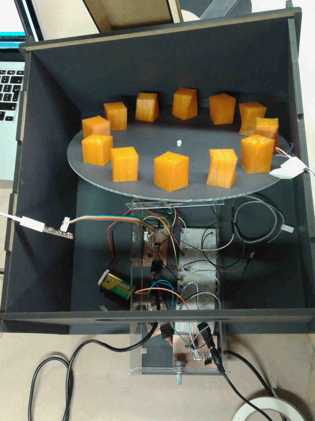
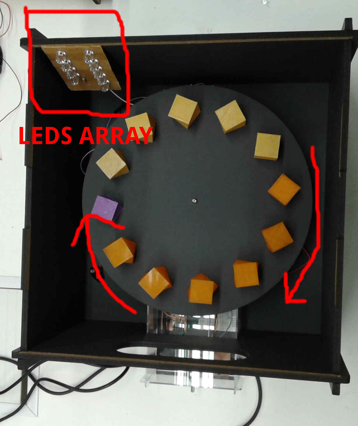
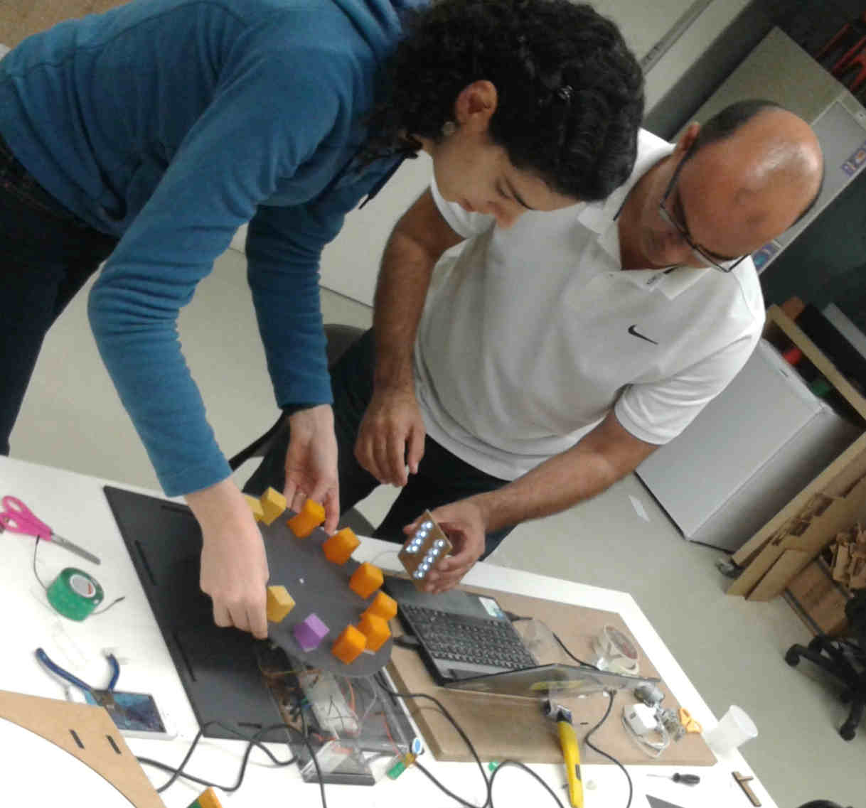
After assembling all parts of the container we noticed that only one LED array board wasn’t sufficient to give the effect that we expected of a strobe light.
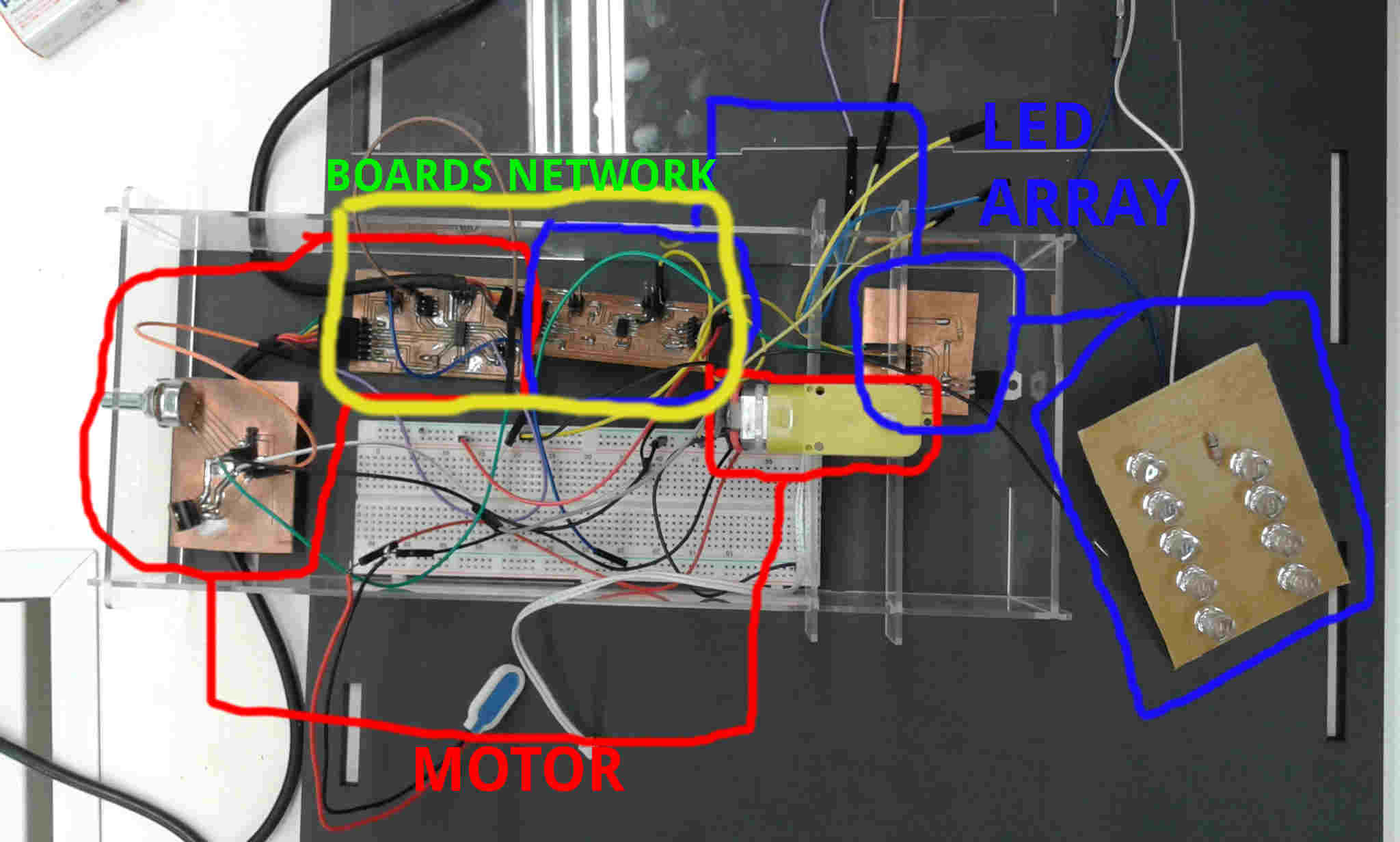
The network/communication between the controller boards (LED and Motor) to syncronize the base movement and the light effect, was not able to do. I need more technical expertise to understand the network/communication using Attiny 44A. I had difficulties with the Arduino IDE libraries as described in my network/communication assignment. This assignment I succeed in blink a led board as a slave, but not sync the motor and the LED array.
The main problem is synchronize the motor and the Leds to produce the Zootrope effect.
Now that the input and output devices are operating satisfactorily, we have to refine things like: sync the motor and the light and adding more light to the circuit.
what have you learned?
I learned lots of things applying the academy assignments in a prototype as output, input, digital fabrication to work simultaneously with mechanical visual effect.
Introduction
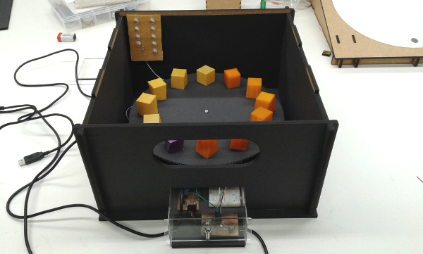
I did the Fab Zootrope with Juliana Henno and separated the tasks within the project. The idea of the 3D Zoetrope is that we could build a motorized platform that could be adjusted in relation of the blinking LED. The strobe effect generated by the blinking LEDs will cause an illusion of a camera shutter in which the flickering image(s) on the platform will give an idea of being in a constant motion without any breaks or intervals.
This project could be possible with ours assignments like:
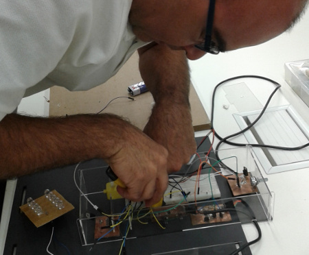
First I designed the OutPut/Input/NetWork project boards, the result was an board that can be programmed to control the motor with a potentiometer.See my documentation Output devices
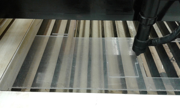
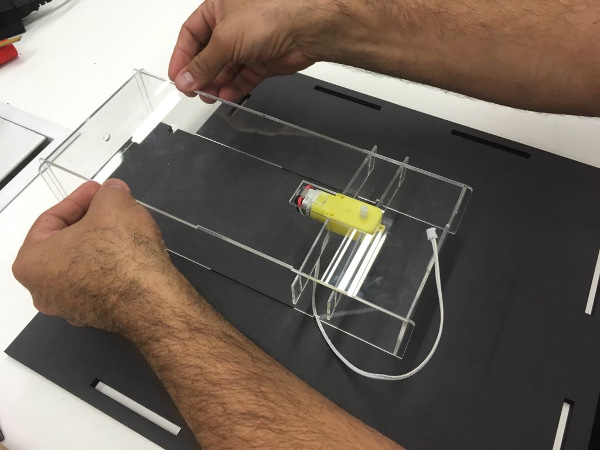
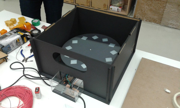
After that, I designed a box (material - Acrylic 2mm/thikness) to fix the motor and enclosure the boards and the platform to put the 3D models. I did with Rhinoceros software and cut with a laser cut see my process: Computer-controlled_cutting
Motor Potenciometer from Alex Angelo on Vimeo.
Testing the motor without the base inside the box.
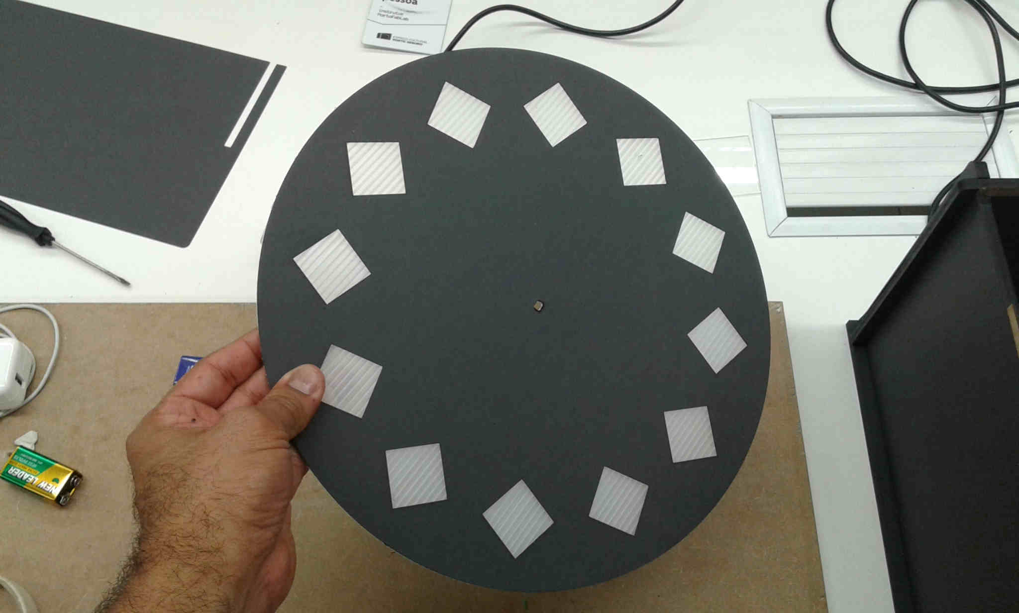
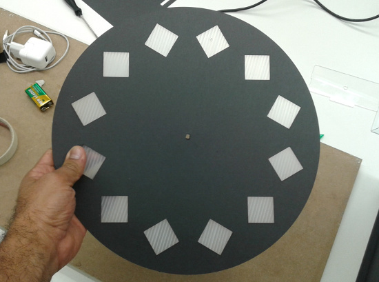
I fabricated with corrugated plastic (4mm/thickness) in a lasercut and covered it with paper (color black)
Testing the circuits all together
Motor problems from Alex Angelo on Vimeo.
First problems with the base and the motor.The temporary solution was to use a new battery that could rotate the motor for a few minutes.
3Dzoetrope1 from Juliana Henno on Vimeo.