Final Project - 3D Zoetrope
The final project that me and Alex Garcia (also a continuing student from FabAcademy 2013) chose to make is a 3D Zoetrope. This project was only possible to make because we separate the tasks within the project.
The idea of the 3D Zoetrope is that we could build a motorized platform that could be adjusted in relation of the blinking LED. The strobe effect generated by the blinking LEDs will cause an illusion of a camera shutter in which the flickering image(s) on the platform will give an idea of being in a constant motion without any breaks or intervals.
In order to amplify the contrast between darkness and light, the platform was projected to be enclosed inside of a container. This way, the light would be blocked from outside and the only brightness inside would be provided by the Strobe blinking effect.
Another reason we decided to go for this project is that it encompasses most of the assignments previously made in the course. As it will be clear in the topics below, assignments like Computer-Aided Design, Computer-controlled Cutting, Electronics Production, 3D Scanning and Printing, Electronics Design, Embedded Programming, Machine Design, Output Devices and Input Devices.
Why not using a phonograph player?
Before starting this assignment we did an extensive research to decide if our project would be a good choice (while concentrating all the knowledge we had gain) and at the same time be somewhat innovative. The closest idea that we found are the John Edmark platforms that are used to rotate the “Blooms”, that are 3D printed sculptures designed to be animated under a strobe light. The difference is that in Edmark’s Bloom, the idea is not to animate multiple 3D models but rather to give an impression of a “living” sculpture. Also in our project it was mandatory that a dark environment could be created by “hiding” the 3D models away from the light. If this choice will be successful it will be possible to check along this documentation!
Also in our research we found out that most of the 3D Zoetrope projects were made based on a phonograph player structure. There are two down parts on doing that, the first is that we wanted and we are supposed to really create something from scratch, and second is that the number of revolutions per minute (RPM) of the phonograph player was too low (78 RPM – originally defined to make the sounds audible), not allowing us to play efficiently with it’s relation to the strobe light. The RPM of John Edmark’s turntable platform for Bloom for example is 756 RPM synced with a strobe running at 33 flashes/second.
This synchronization of the rotation speed in relation to the strobe flashes is important to cause an illusion of natural movement. The way the sculpture was designed, following the logic of the phyllotaxy is responsible for this effect. According to Edmark “each petal on the bloom is placed at a unique distance from the top-center of the form”.
The idea of using an engine with more revolutions per second and able to be controlled by a potentiometer gives us a broader field to analyze the relations between the strobe light and velocity of the spinning in real time.
Building our own microcontroller board
Me and Alex Garcia designed our own microcontroller boards aiming to access both the LEDs and the motor of the 3D Zoetrope. The microcontroller board developed to work with the LED boards was documented in my “Output Devices” assignment and the microcontroller board dedicated to the motor board was documented in Alex Garcia assignment page.
Alex Garcia - Microcontroller Board - Motor:
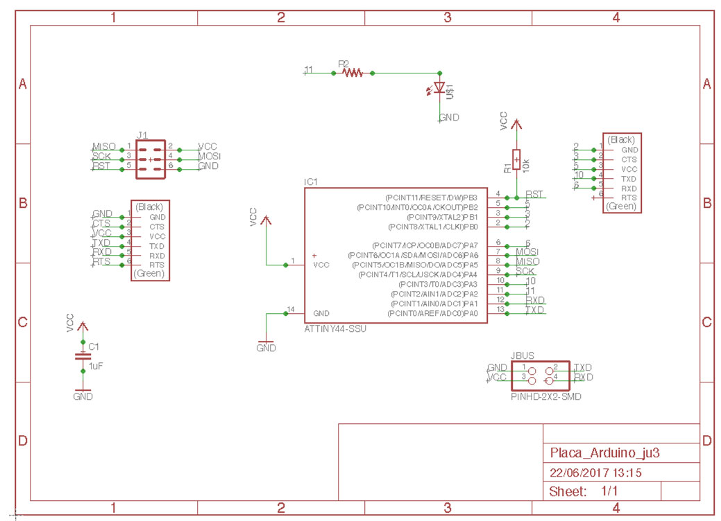
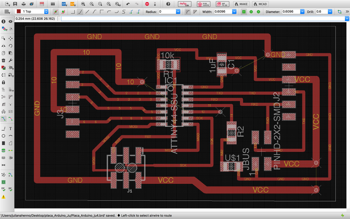
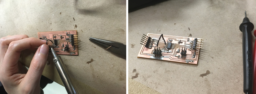
Juliana Henno - Microcontroller Board - LED:

Engine Circuit – Alex Garcia
The complete documentation for the driver board can be seen in this link
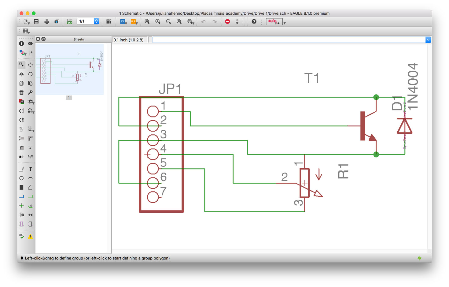
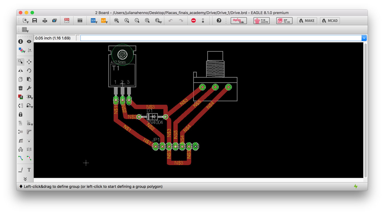


The circuit that Alex designed is able to control a 240RPM motor rotation with the help of a potentiometer. The potentiometer will control the amount of resistance of the current in the circuit. This mean that the person who would interact with the 3D Zoetrope could, from outside the container, control the platform speed affecting the way the animation could be perceived.
This board contain a potentiometer, a TIP 122 transistor (DIP component), that has a base, a coletor and an emissor.
Engine rotating from Juliana Henno on Vimeo.
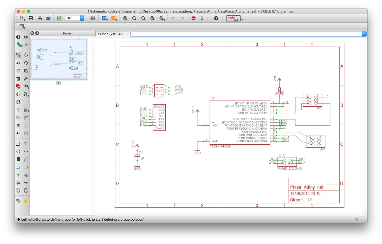
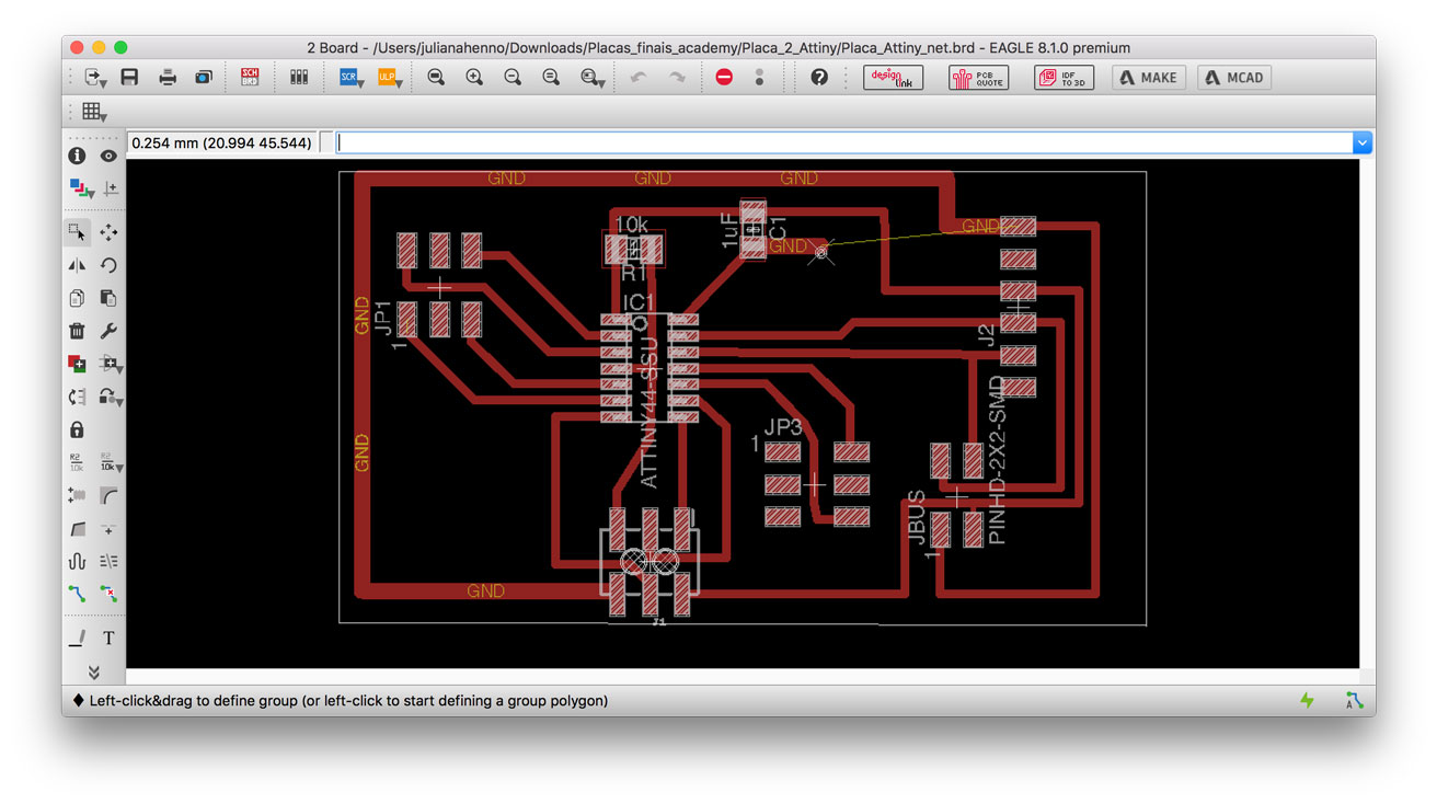
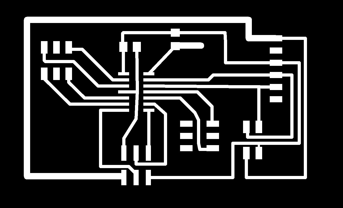
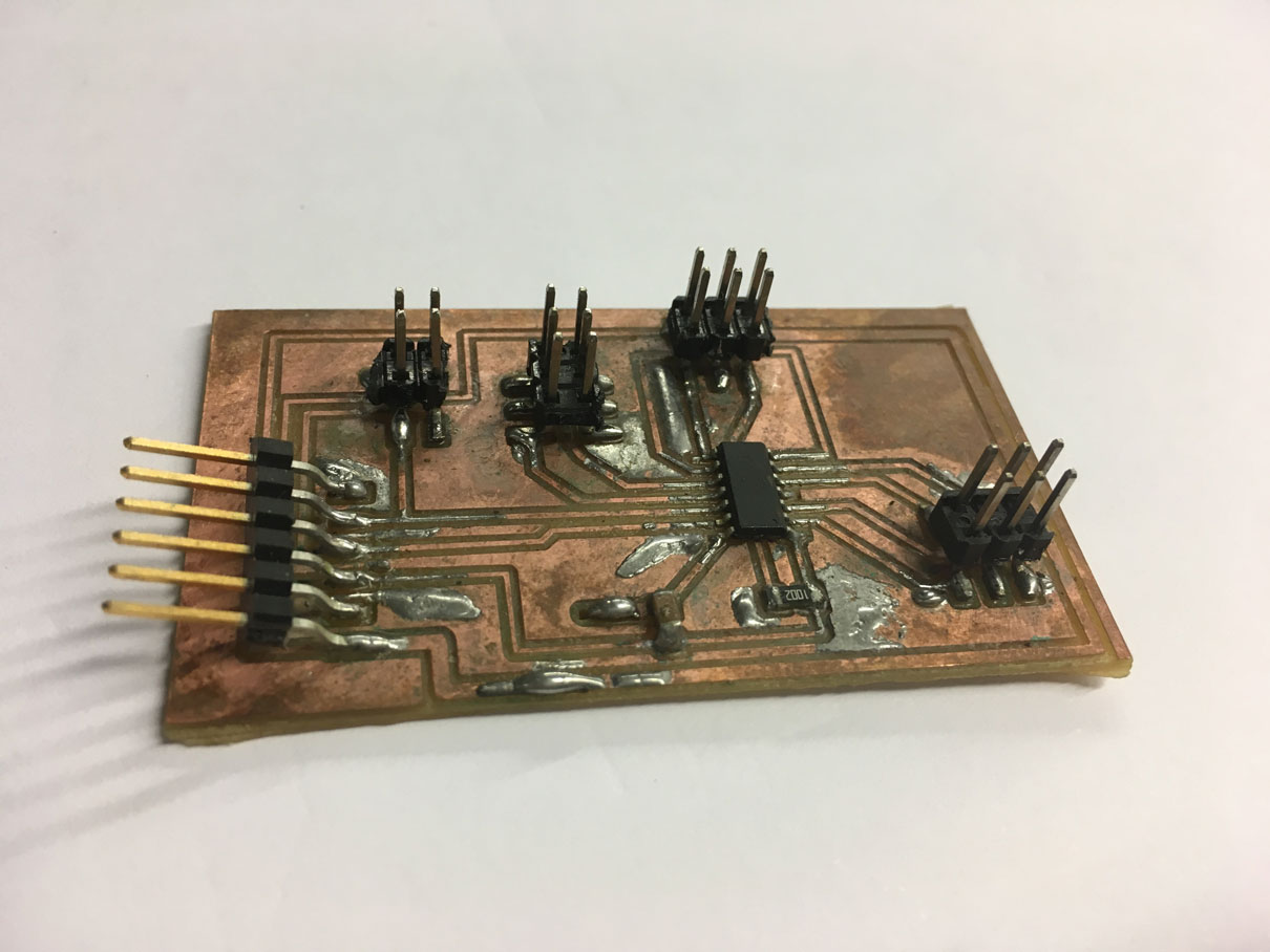
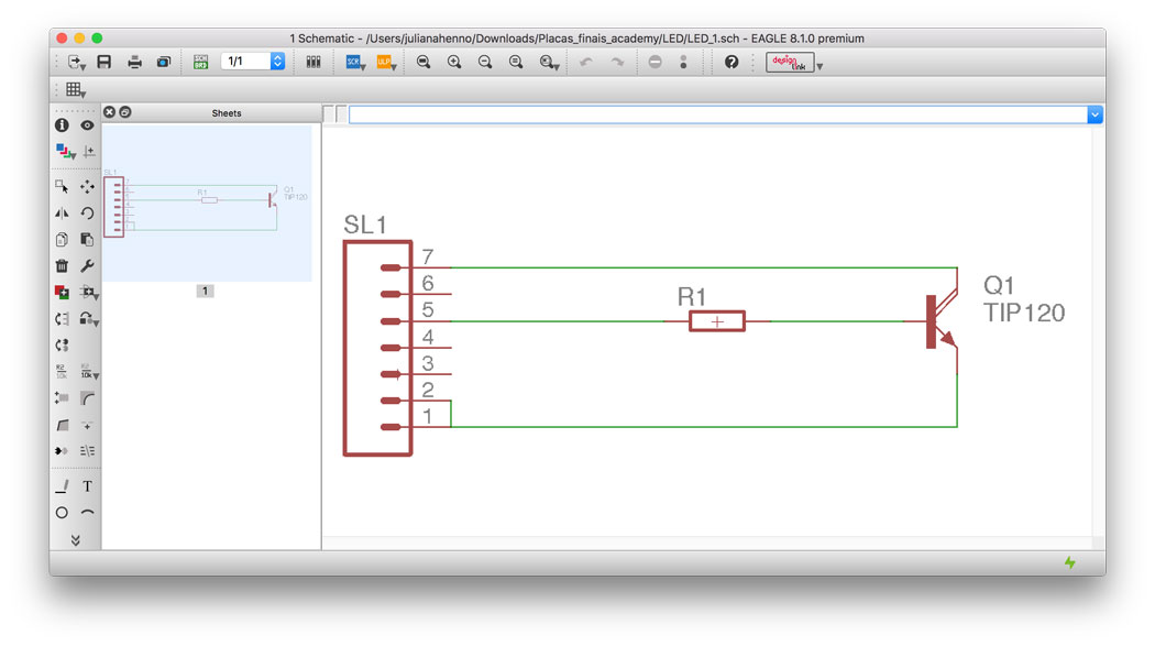
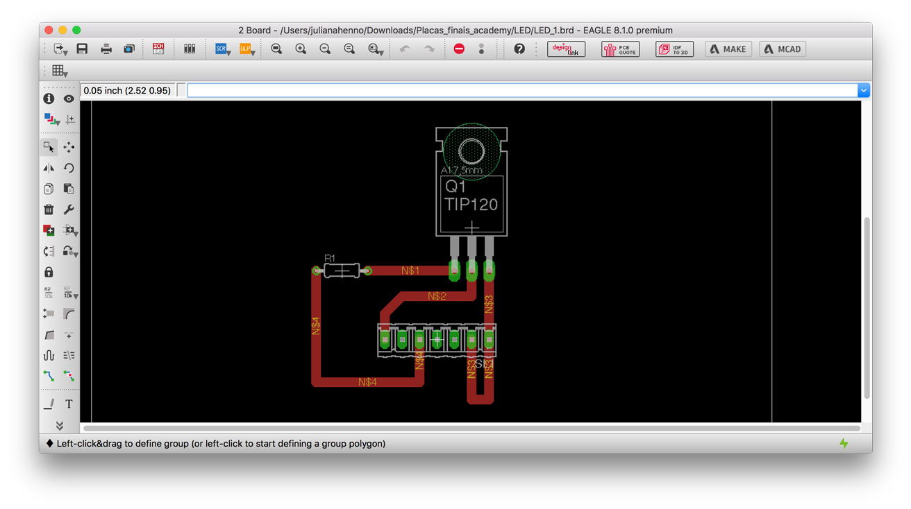
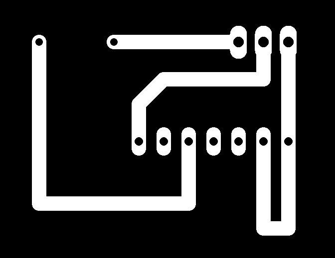
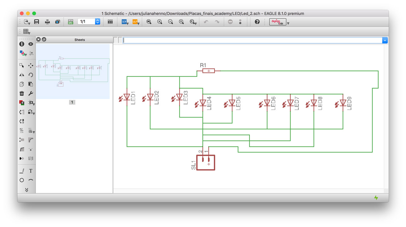
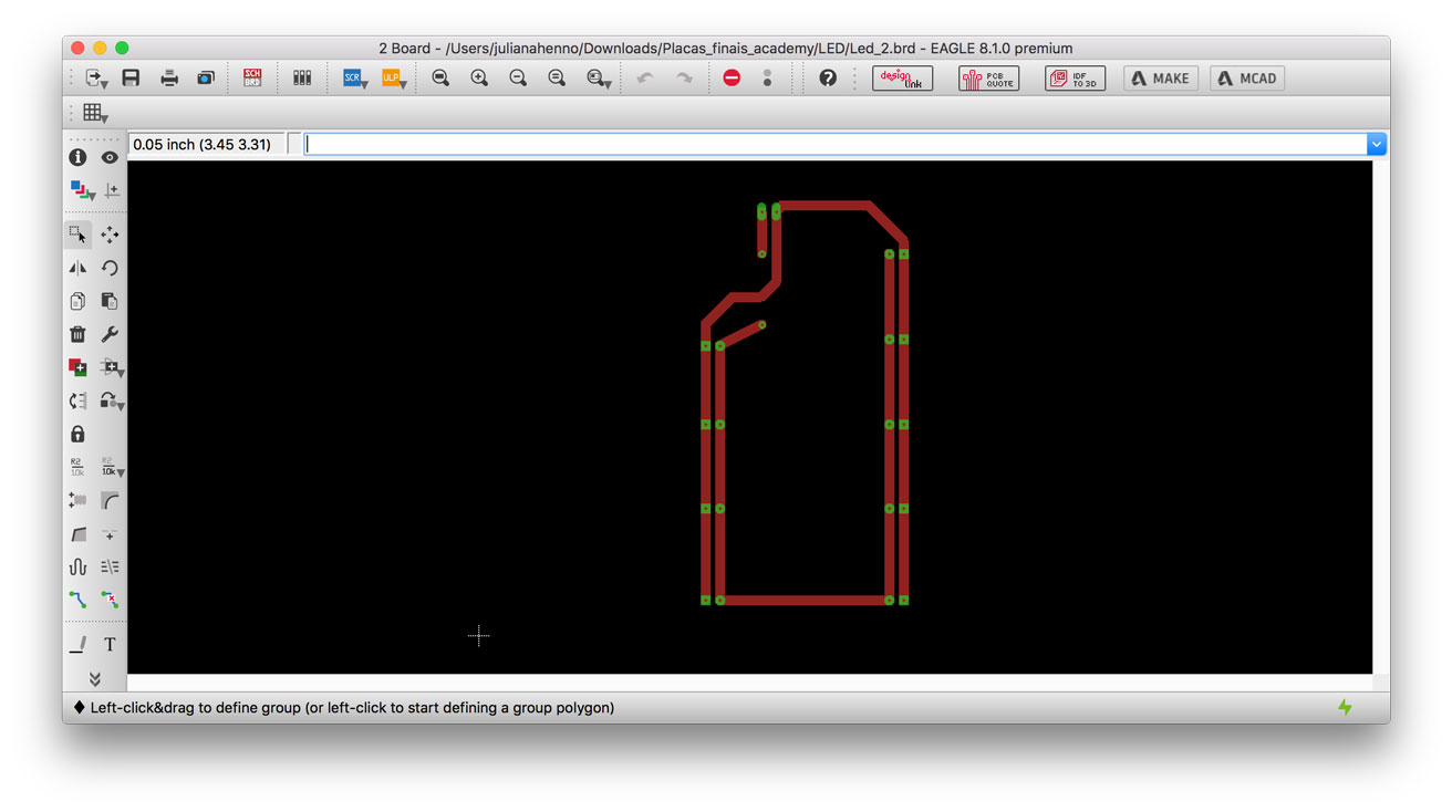
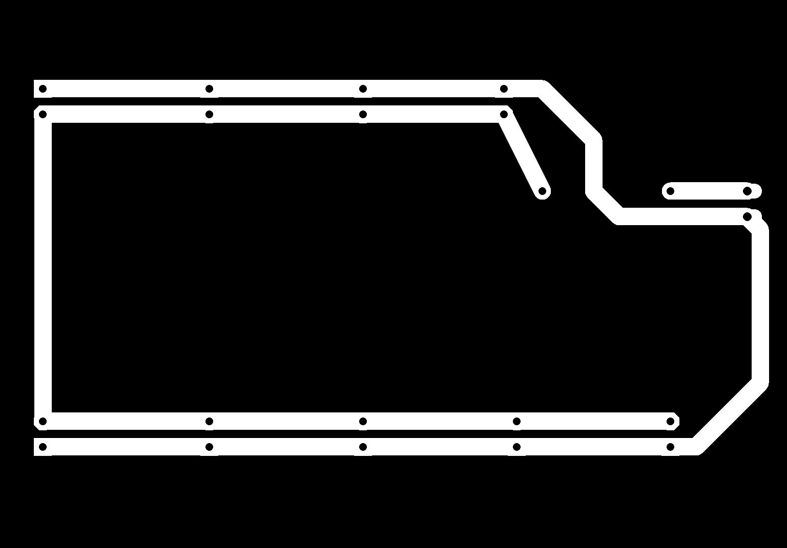
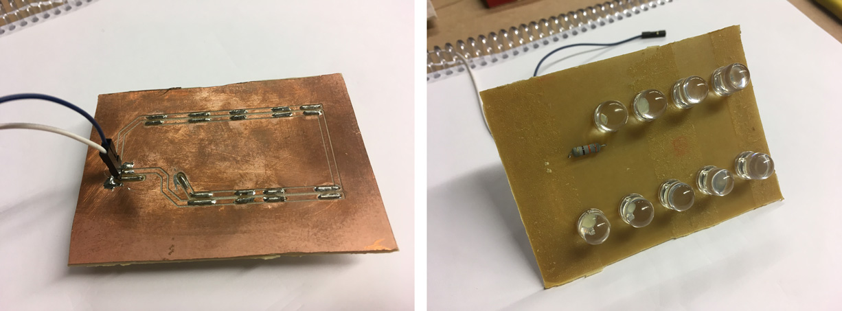
LED strobe circuit – Juliana Henno
The complete documentation for both LED boards can be seen in this link
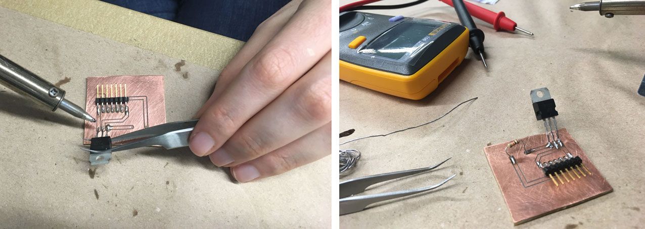
LED blinking from Juliana Henno on Vimeo.
The circuit to control the strobe light LED was fragmented in two different boards(PCB). The reason why we decide it was that the board with the LEDs should be positioned in a specified distance from the platform and at the same time connected to the main board that would be grounded and receive the current.
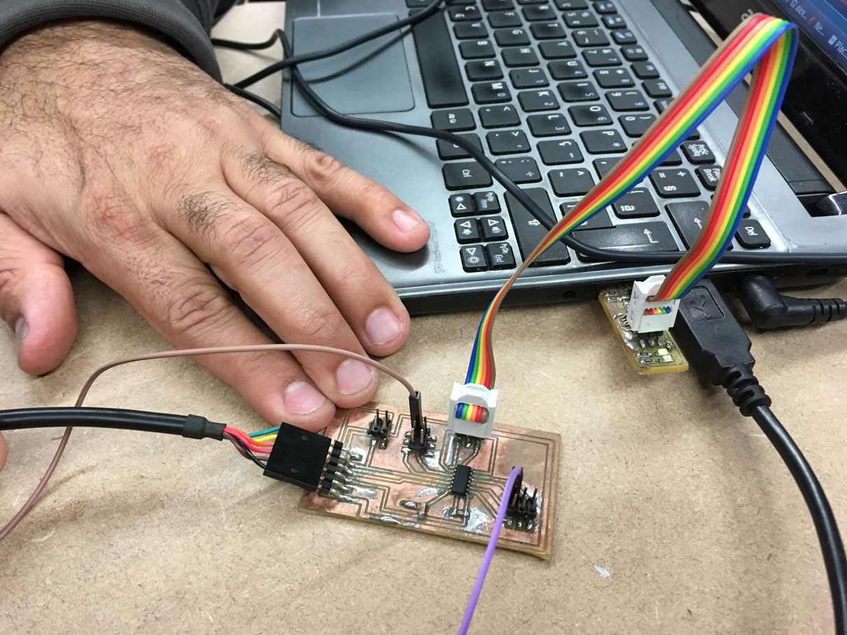
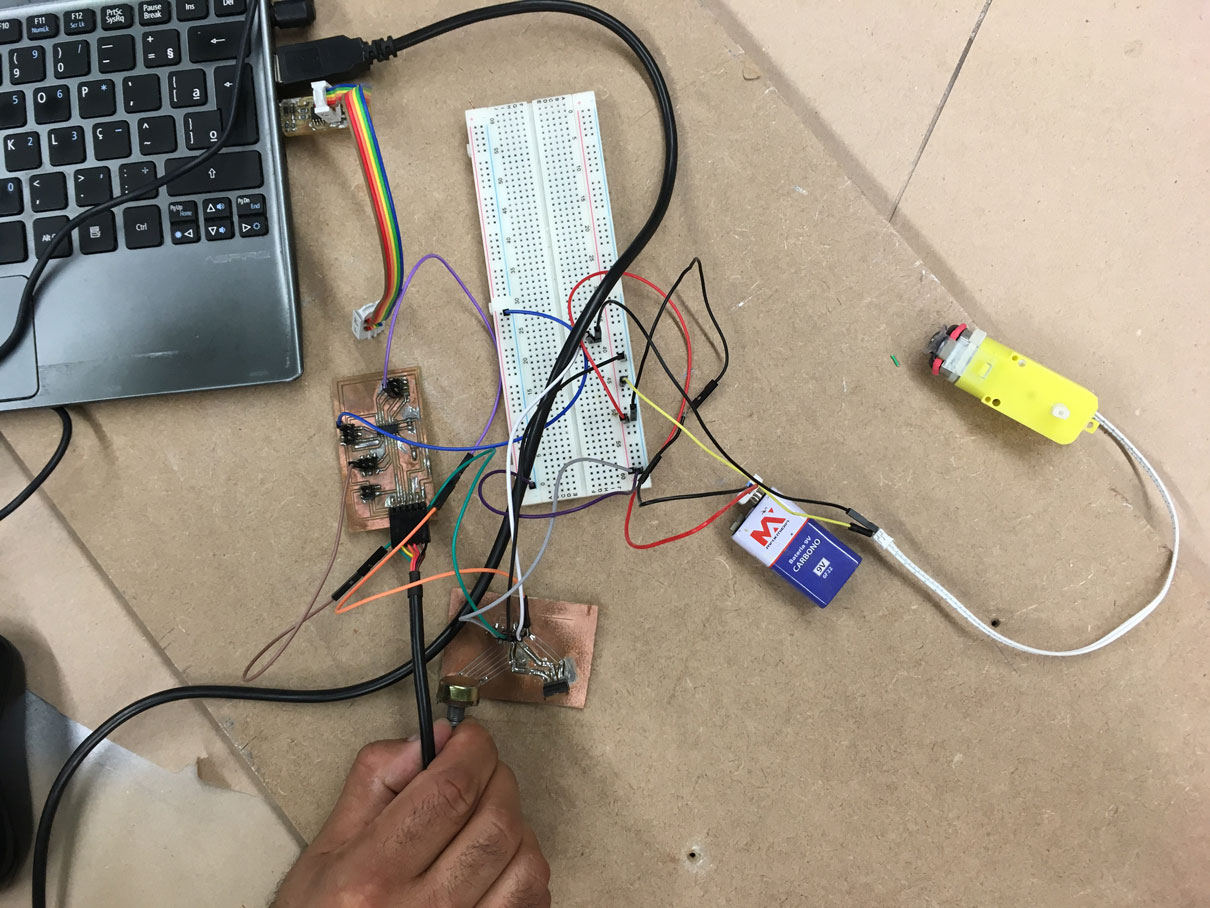
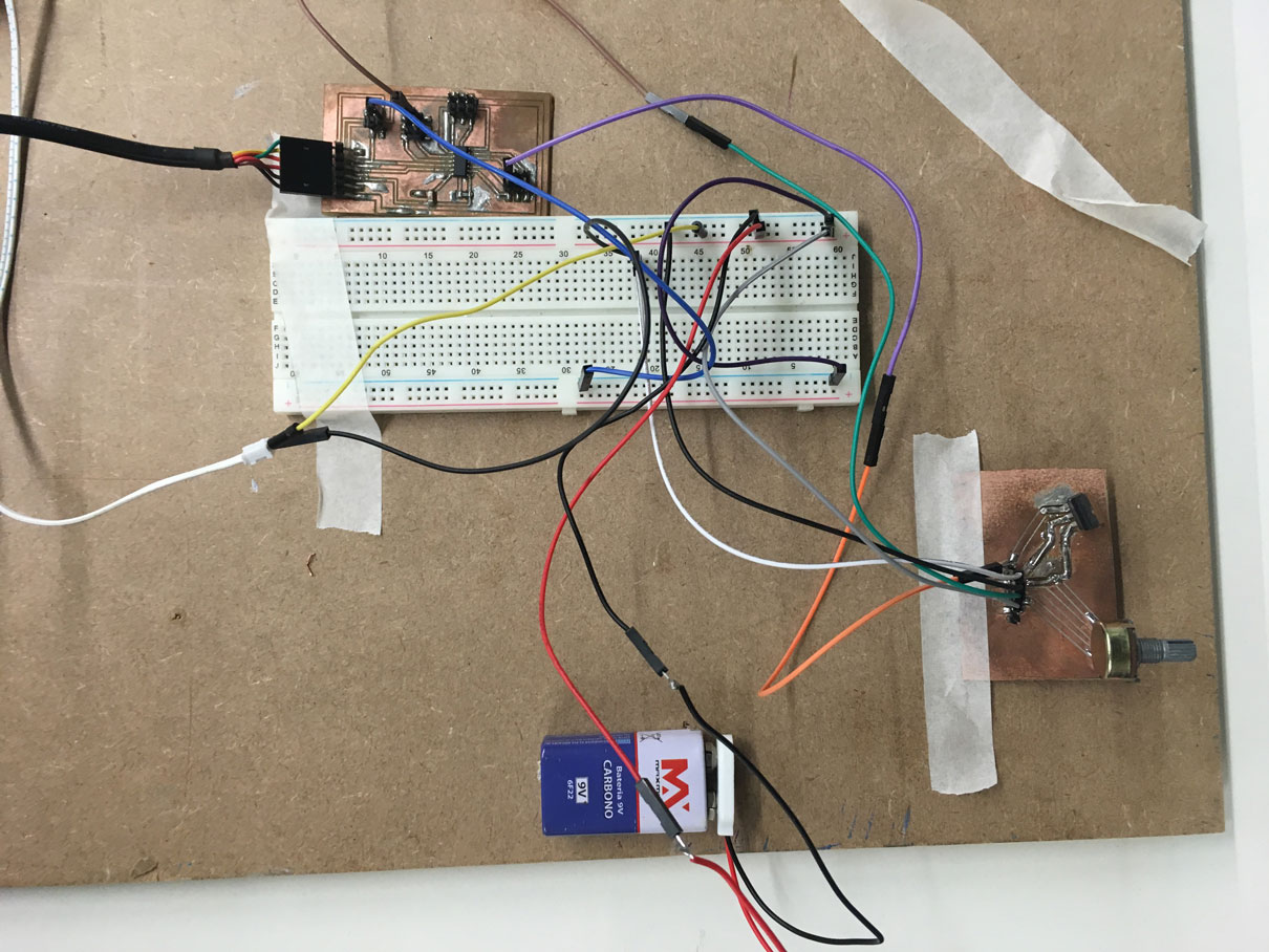
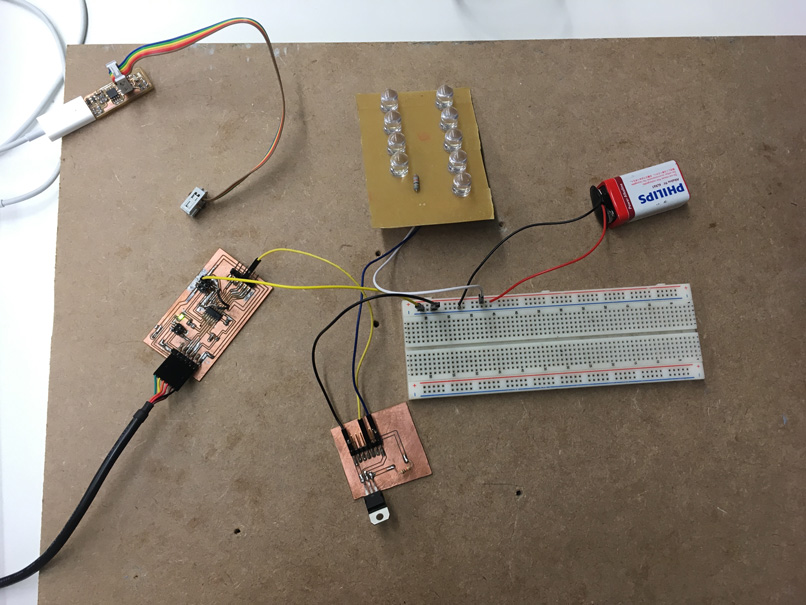
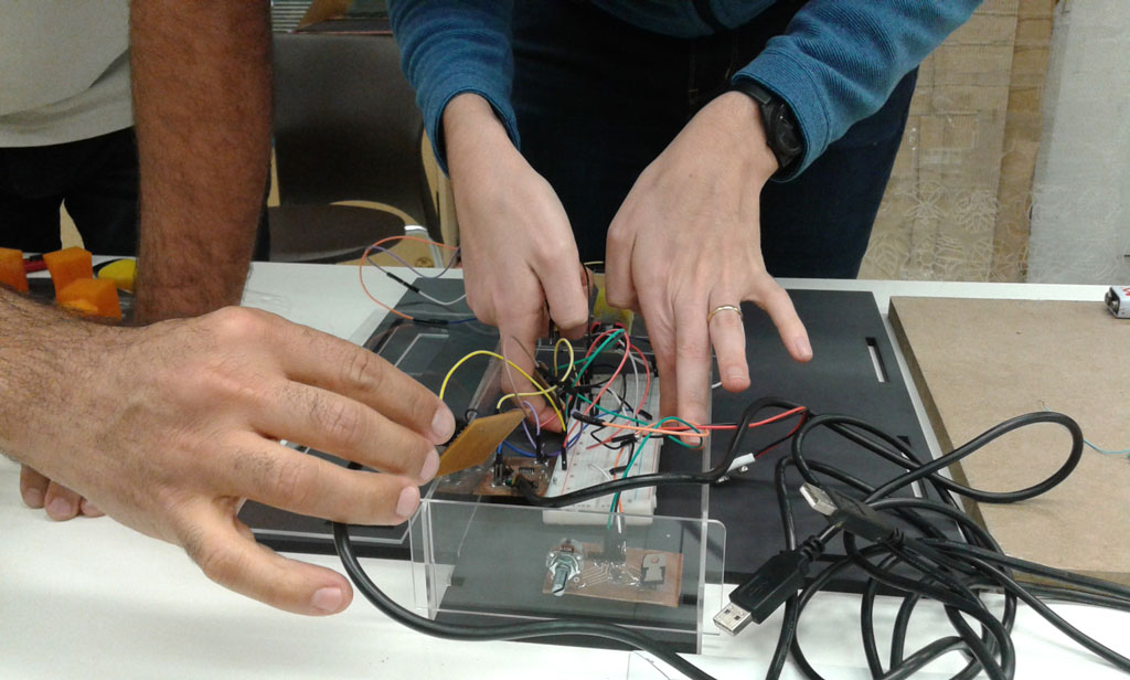
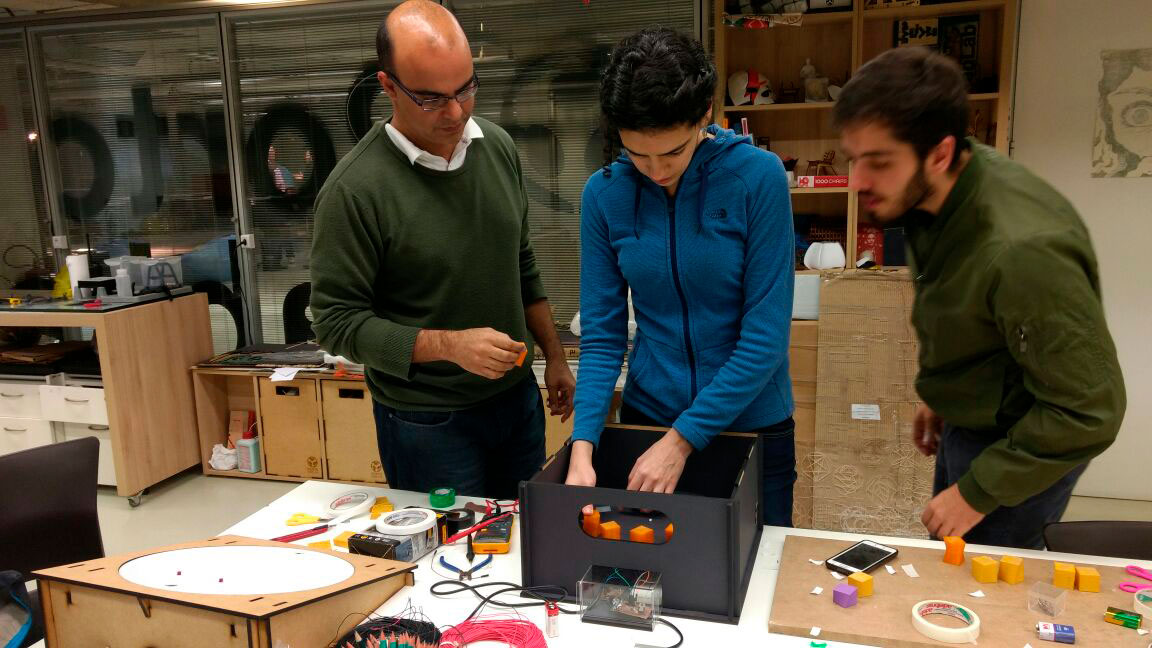
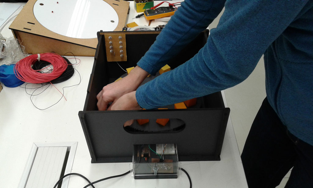
Putting together the circuits
After me and Alex succeeded on building our own circuits, we put them together to check it’s size before starting the adjustments in the container that I was going to design and the acrylic box to hide the circuits that Alex was going to design.
Engine plus LED working from Juliana Henno on Vimeo.
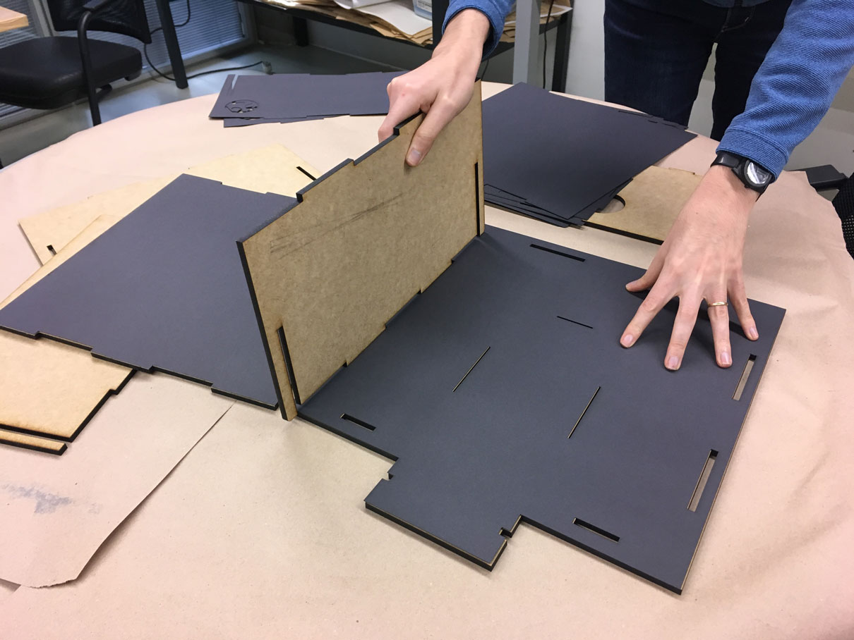
Container for the 3D Zoetrope - Juliana Henno:
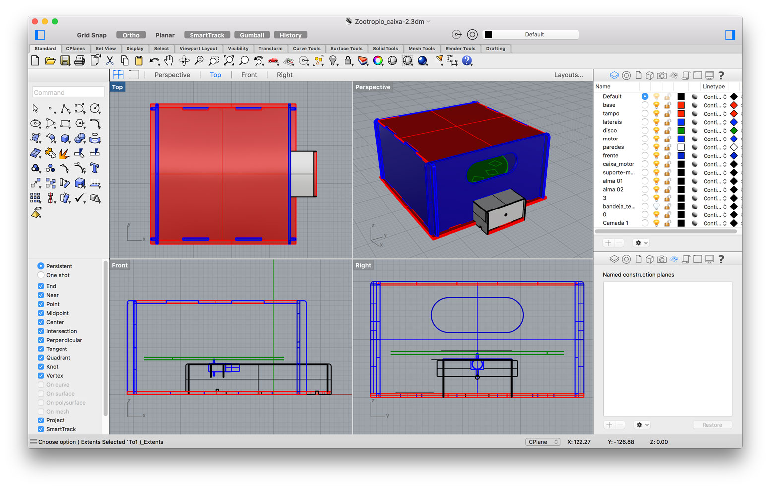
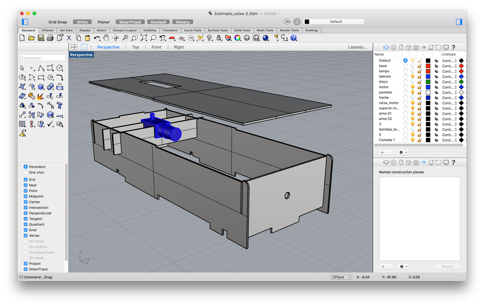
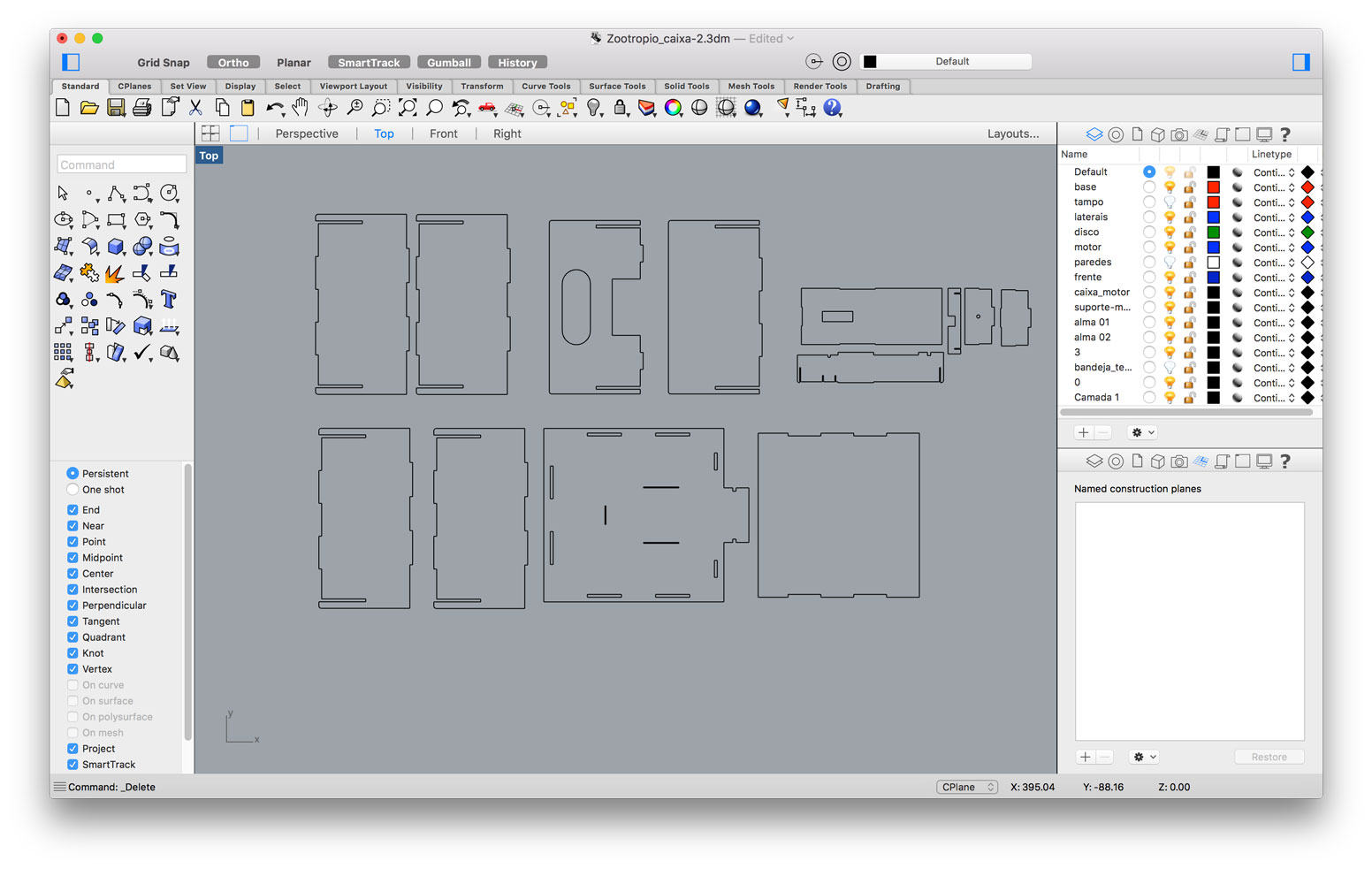
The container for the strobe was first envisioned by me in this earlier assignment in witch I had no idea yet how me and Alex would distribute and organize the electronics, I only had a proposition of the mechanics and overall look of it. All of the parts of the container were designed to be press fit without the necessity of glue. The design of the container also predict that the front face could be easily removed by sliding it, the main reason for it is to eventually be able to change the 3D models over the platform. All the parts of the container were designed using Rhino 3D.
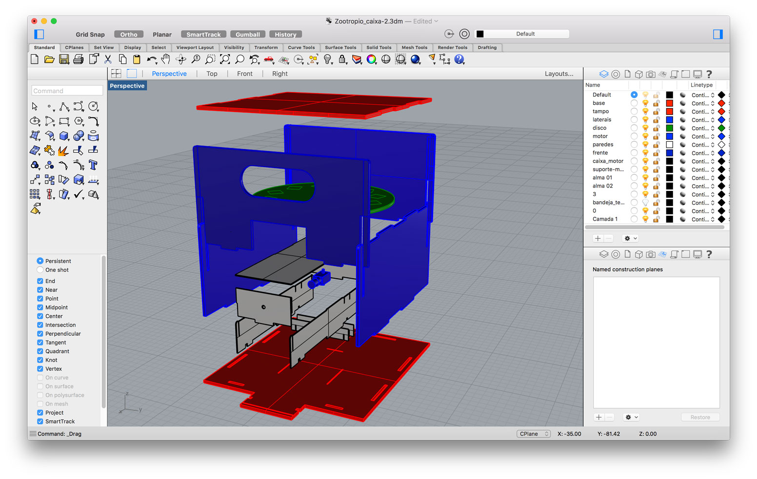
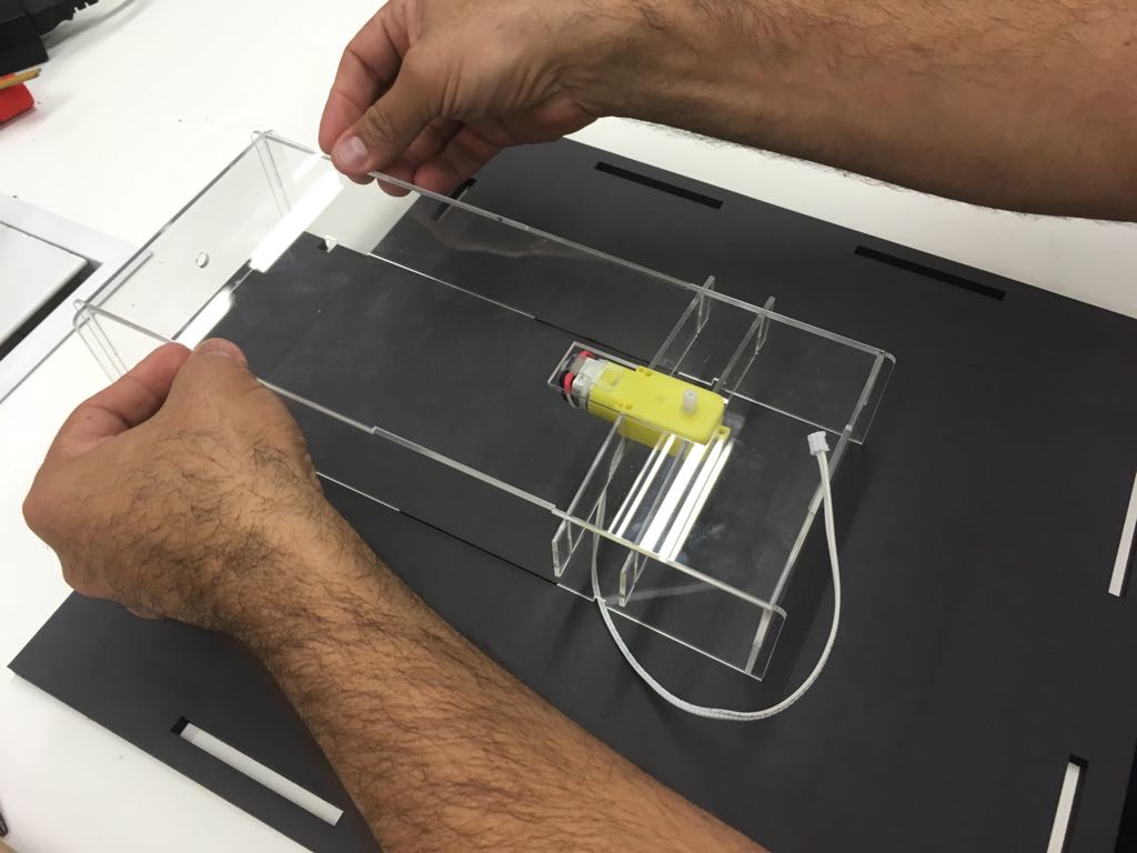
Rotating Platform and engine holder - Alex Garcia:
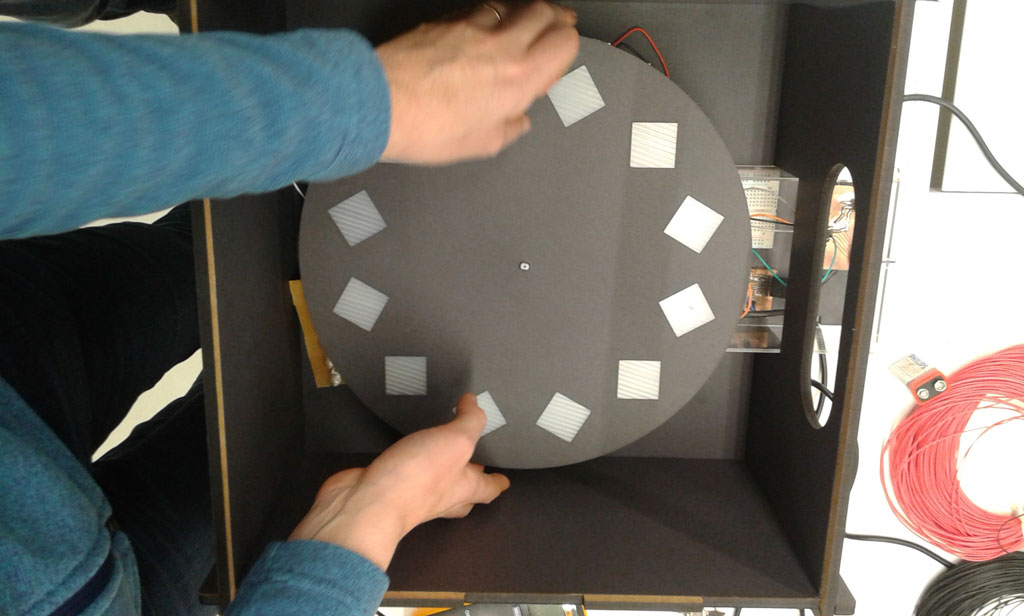
The 30cm diameter platform that Alex Garcia designed will rotate along its center attached by the motor shaft. The material he chose for the platform is corrugated plastic. The reason for that is that the performance of the motor would be reduced in case the weight of the platform would be too heavy. Because the corrugated plastic is a flexible material he decided to connect the motor shaft direct into the platform. For that he had to calculate the kerf once the corrugated plastic edges deforms when being cut by the laser.
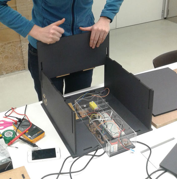
To secure the engine in place while it would be working Alex Garcia designed a support that would be the cover of a box containing all the electronics. This structure was made in acrylic and it places the engine in place avoiding it to shake and destabilize the set of the platform. The support as all the parts of the container were all designed in Rhino 3D.
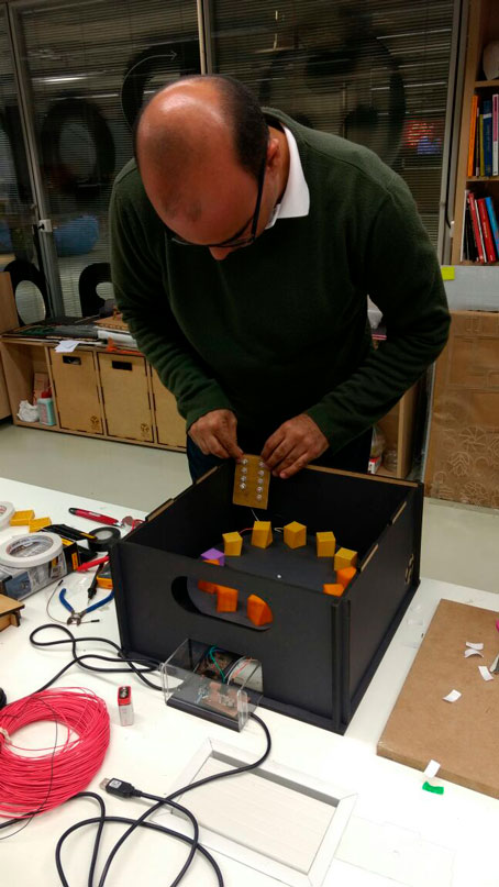
All the circuits will be placed in an acrylic box below the platform. This box is narrow and will project itself outside of the container in order to place the potentiometer at hand so the interactor could access while watching the animation through the slit. From this acrylic box will also be coming out the 2 FTDI cables that should be connected to stablish the circuit. The only circuit board that would be outside this box is the PCB with the LED array, in this case, we’ll have to position it somewhere the flashes could brighten up the models.
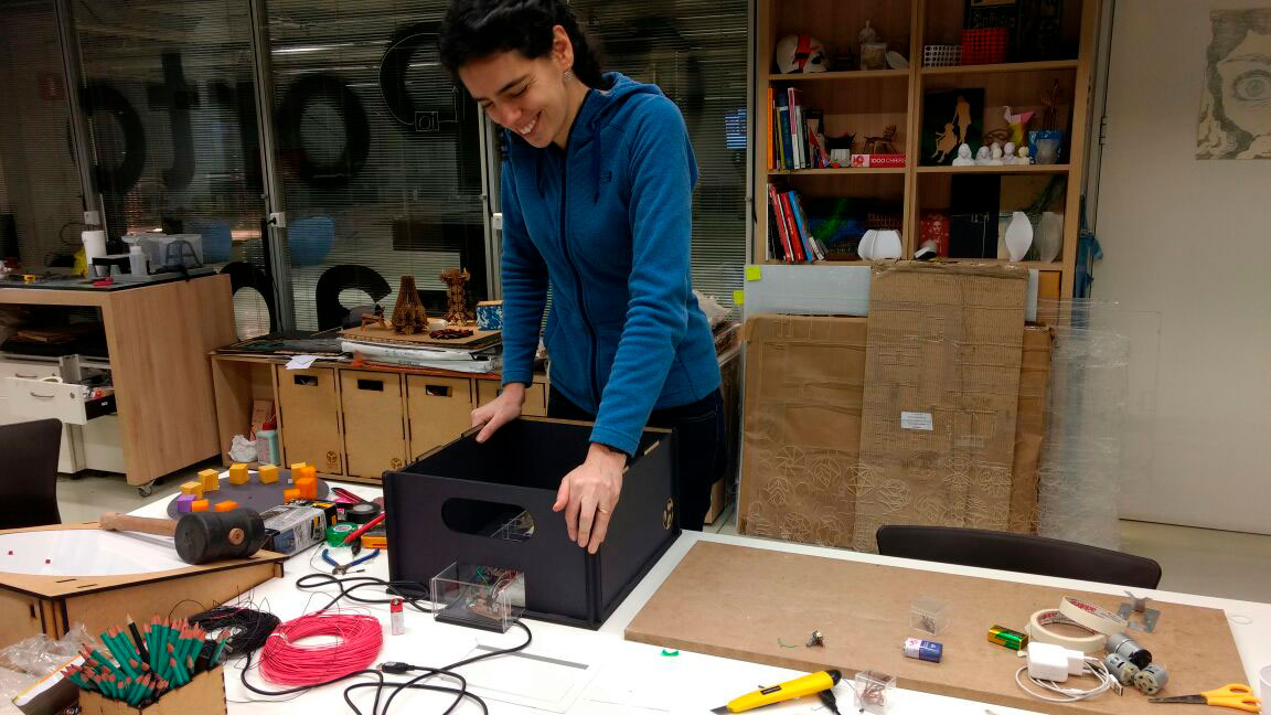
Covering the parts of the container
In order to keep a dark environment inside the box, all the inner walls were covered with black paper. For doing that we used the laser-cutter and a double sided tape.
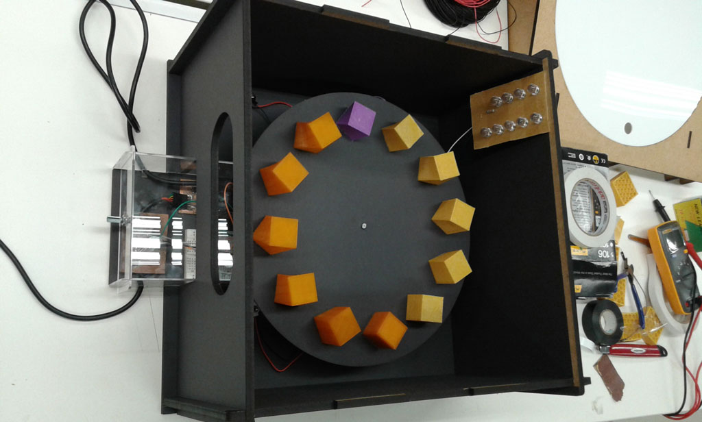
Models in the platform - Juliana Henno:
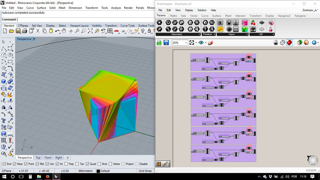
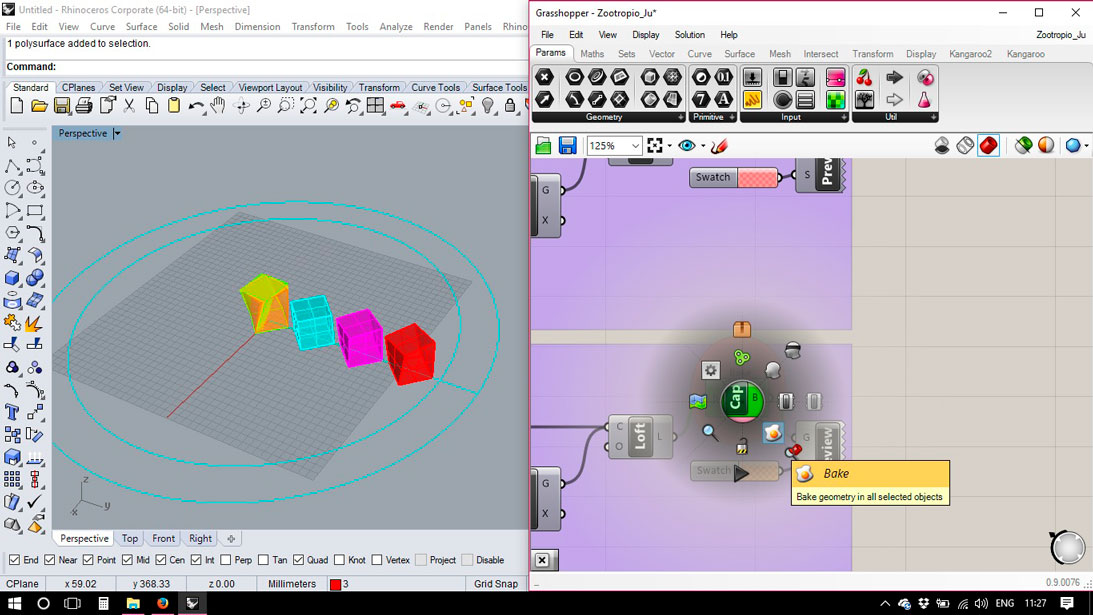
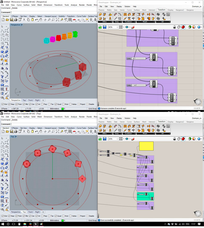
For the design of the models I recalled the 2013 assignment “Computer Controlled Cutting” where I experiment to give an idea of movement out of a series of squares that were dislocated from their centers separated by several layers. By that time I experimented with Grasshopper (www.grasshopper3d.com) to create a “loft” between two squares (each one in a different position) and subtract the result from a block of material that would be later on sliced in a number of layers.
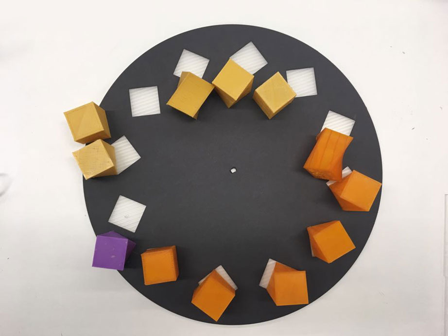
For the final project the 3D model we should define an object that should change slightly while repeating 12 times. From the first to the last the shape should come back to its original shape in order to create an endless loop. So we defined that the first 6 steps should demonstrate a transformation and the last 6 steps it should show the distorted shape coming back to its original in a reverse way.
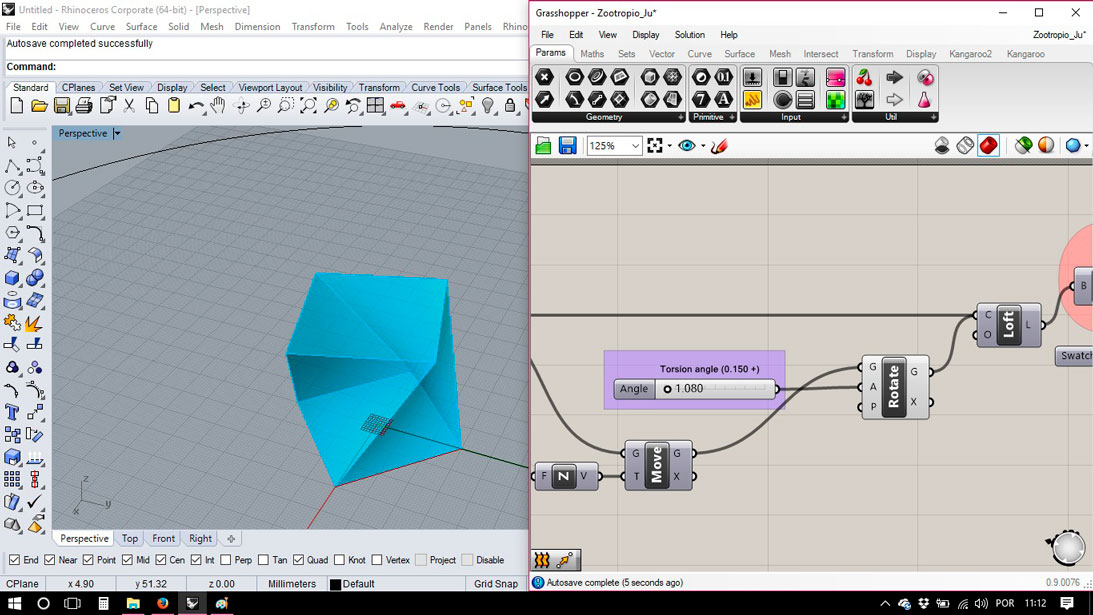
The model resembles the assignment of the square distortion (mentioned earlier) while the model related to the first step is a perfect cube that is the result of the extrusion of a square. The models that follow until the 6th step are the result of a loft departing from the original square to another square slightly rotate in its central angle.
Final Assemblage:
Final Project from Juliana Henno on Vimeo.
Softwares used:
- Rhino3D
- RD Works V8
Machines used:
- Laser cutter
Files: