Output Devices
For this assignment I designed a microcontroller board connected to a LED output that could be useful in my final project. This LED output is a stroboscope, a device that produces regular flashes of light in a programmed time. In my final project the flashing light should work like a shutter creating an illusion of an animated movement into a series of slightly different 3D models placed in a rotatory platform.
Microcontroller board

The microcontroller board that I designed is an adaptation of Echo hello-world board. This board was originally designed to accommodate a microcontroller that would be part of a circuit to light a LED by just pressing or holding a push button (depending on the instructions programmed).
Components (microcontroller board):
- 1 Resistor 10K
- 1 Resistor 499
- 2 header FTDI 6 pins
- 1 Capacitor 1 uF
- 1 ATtiny 44A
- 1 header 6 pin
- 1 header 4 pin
- 1 LED
Eagle:
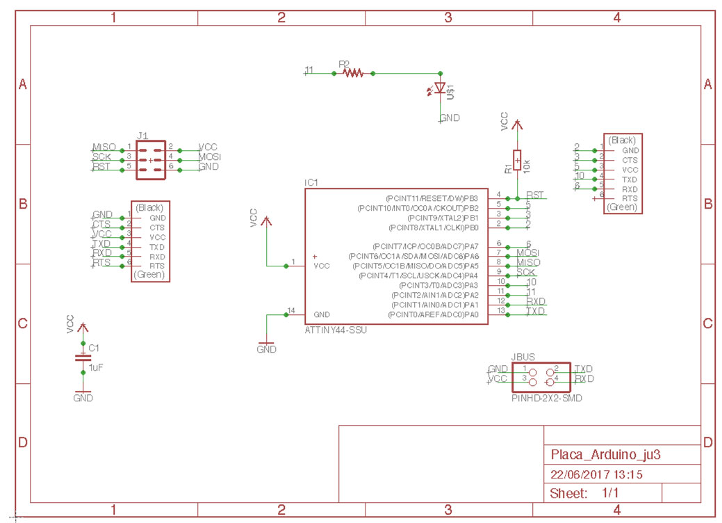
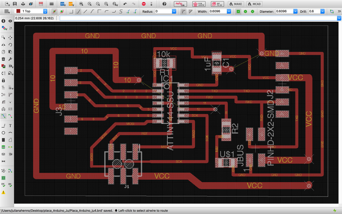
I designed the microcontroller board to have a ATtiny 44, a built in LED + resistor, a 6 pin for communication with my FabTinyISP, a 10k resistor and a 1uF capacitor, a 6 pin for the FTDI connection with the computer and a 9 pin to other ports of the microcontroller. I was not able to design the circuit without the help of 3 jumpers, the first connects the VCC, the second connects the GND and the third connects the port 10 from the microcontroller to the pin head. This microcontroller board will receive once instructions through the FabTinyISP so it could be able to operate solely in the communication with the LED boards.
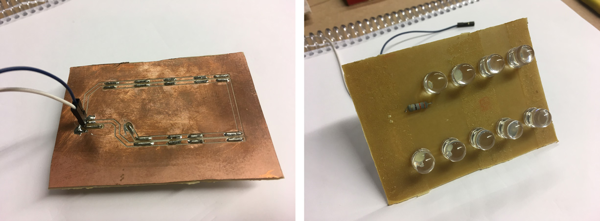
Output: Strobe Light
Envisioning the final use of this output device, the Strobe light array should be placed somewhere inside a container of the 3D Zoetrope. To better accommodate this light array I decided to build two different boards connected to each other by a connector. Doing that I could place the main board hidden bellow the platform together with the other electronics and the LED array board near to the platform.
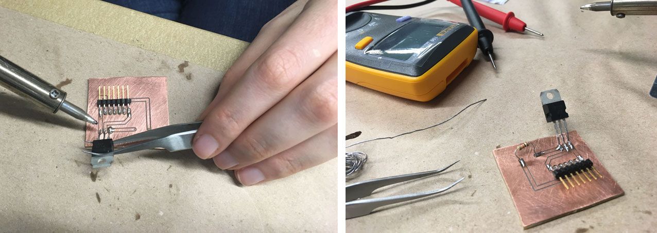
Components (main board):
- 1 header 6 pin
- 1 10k resistor
- 1 transistor TIP 120
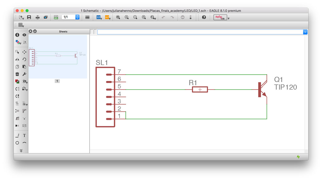
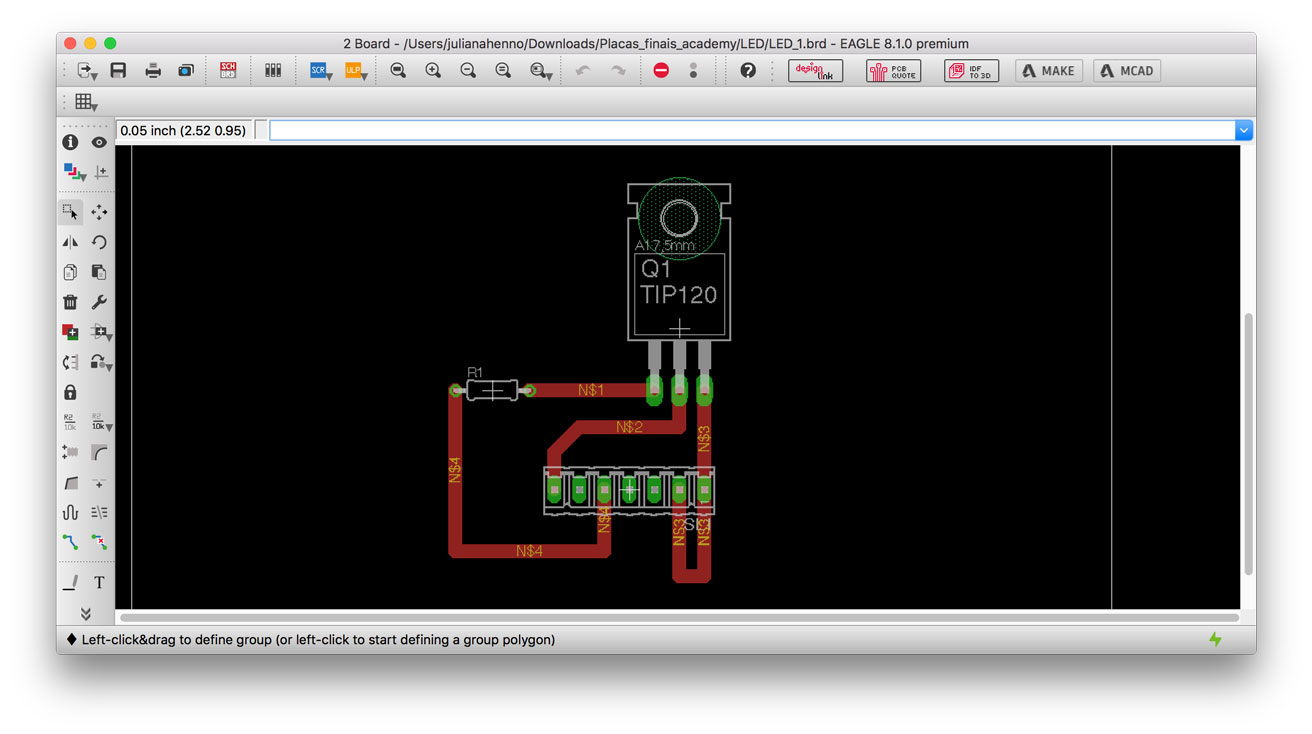
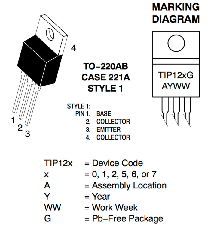
The main board has a TIP 122 transistor that has a base, a coletor and an emissor. Its function is to direct the information of the blinking, that comes from the microcontroller, to the LED array board. The base end of the transistor is linked through a resistor to a pin that I connected to the pin 5 (PB2) of the microcontroller board. The coletor end of the transistor is linked to the negative side of the LED array board. The emissor end of the transistor is connected to the GND(ground) that I positioned in a breadboard.
Components (LED array board):
- 9 White LED
- 1 resistor
Eagle (main board):
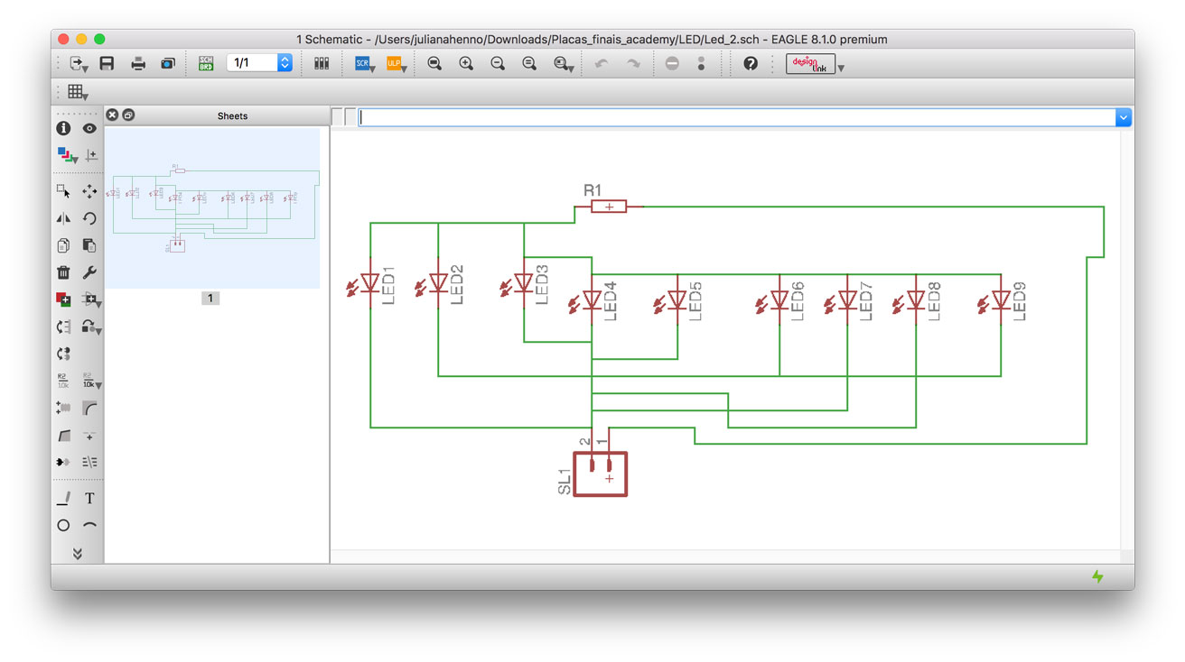
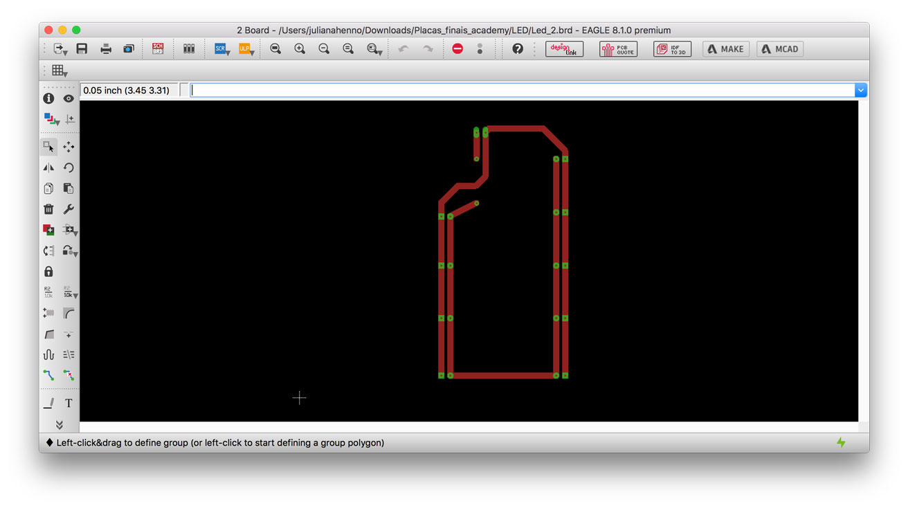
The LED array board has a simple circuit that distributes 9 LEDs having them secured by a resistor. It receives the information from the main board about the delay of the LED when blinking. The negative end of the circuit is connected to the transistor collector (as mentioned before) and the positive side is placed at the breadboard.
Milling – Roland MDX 40A (Insper FabLab)
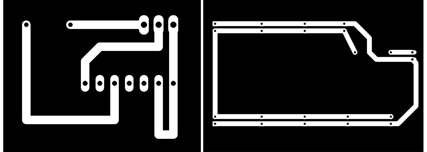
In order to set the machine I generated the .RML files of the .PNG boards using FabModules (fabmodules.org):
- Input File: chose image (.PNG) and uploaded it;
- Output Format: chose “Roland Mill (.RML)” – Process “PCB traces (1/64)”;
- Machine Settings: set the machine as “MDX-40” and change the following parameters: cut depth (0.1mm), tool diameter (0.1mm), number of offsets (8), offset overlap (40%).
- Hit calculate and save.
- Eagle
- Adobe Photoshop
- Fab Modules / VCarve
- Arduino 1.8.2 IDE
- Roland MDX 40-A
- Table Drilling Machine
The milling can be started from FabModules if your computer is connected to the machine. In my case I exported the .RML before going to the lab, so I send the files straight from Roland VPanel software. In this software I also defined the XY origin and detected the Z origin with the help of a sensor.
Note that this .RML configuration is set only for carving the circuit traces. It’s also necessary to generate a .RML file for cutting the exterior of the board. The configuration in this case will change to “PCB outline (1/32)”, the cut depth (0.3mm), tool diameter (0.9mm), offset overlap (40%).
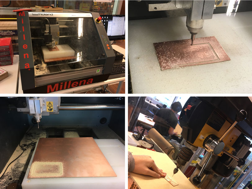
The holes for the jumpers were made by me manually using a table drilling machine.
Soldered boards:
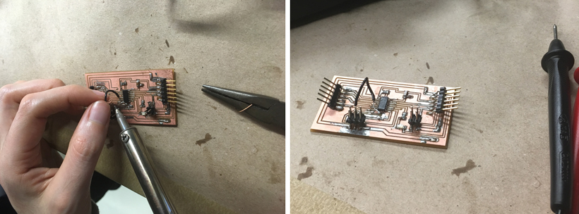
Soldering the boards was a straightforward process. I had only issues when I soldered the microcontroller board because the filler was out of the edge being the trails too narrow and close to each other. It took me a while cleaning the filler excess and to restore the circuit. In the end I performed a continuity test with a multimeter to test if all the trails were connected to the correct point and the result was satisfactory!
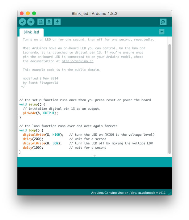
Programming:
To program the microcontroller board for it to instruct the LED boards to blink I used an Arduino IDE with a programming sketch that is very basic. The sketch, that is in public domain and was developed by Scott Fitzgerald. I made some adaptations to the program defining the pin 8 as an output and I declared that the pin 8, in this case the LED array, should be on for a period of 200 milliseconds and stay off for 100 milliseconds in a constant loop.
When using Arduino IDE I should use the pin named accordingly the pins of a Arduino. In order to know exactly what is the correct pin I should refer when programming Attiny I used the following diagram:
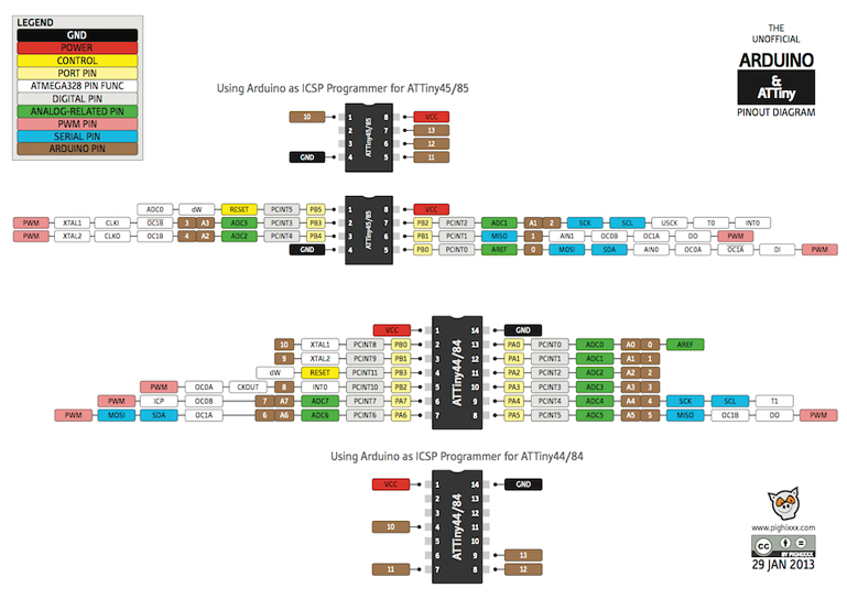
So according to the graphic the port 5 (PB2), that I originally planned to connect the LED array, is compatible to the pin 8 of the Arduino. That’s why I refer to pin 8 in the Arduino Sketch.
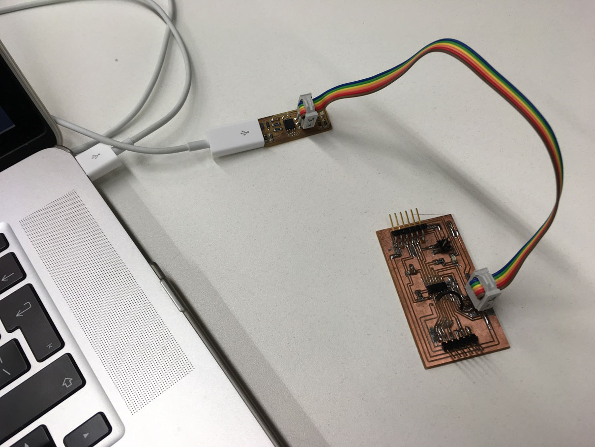
To transfer the sketch to the microcontroller I used my FabTinyISP that is an in-system programmer (built on assignment 4) that will allow me to program my microcontroller board using a 6 pin ribbon cable.
It’s important to note that before uploading the definitions to the microcontroller I should adjust the tool configurations of the board:
Board: board ATtiny 24/44/84
Processor: ATtiny 44
Clock: clock external 20MHz
Programmer: USBtinyISP
Being it set up I run “Burn Bootloader” and “Verify” if I get no error message back I upload it to the microcontroller board.
Testing the output boards:
After the microcontroller board was programmed I disconnected it from the FabTinyISP and let only the FTDI cable connected.
I started connecting the wires between the boards just like I mentioned earlier and used a breadboard to help me in this process. I added a 9V battery to give enough current to the entire circuit made of two boards + microcontroller.
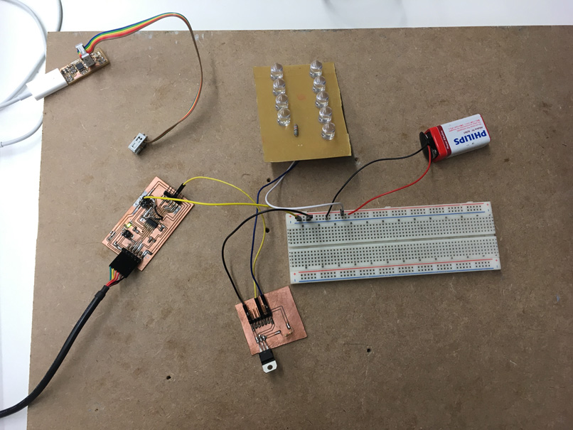
When I connected all the cables and plugged the 9V battery to the breadboard the LED array board started to blink in a constant loop as expected. I tested doing some minor modifications on the code based on the result of the blinking LED in order to change the delay time of the LED trying to make it faster or slower. This also went fine!
It’s important to notice that for every time that I changed the code I had to plug again the FabtinyISP to the microcontroller board and define again the presets in Arduino IDE tools in order to reprogram the board.
LED blinking from Juliana Henno on Vimeo.
Softwares used:
Machines used:
Files: