Computer-Aided Design
For this assignment I had to design a possible final project while learning about different design tools.
Zoetrope box
I’ve been working with 2D vector for about 15 years by now and the software that I use the most is Adobe Illustrator, although I could also use similar vector graphics softwares like Corel Draw and Inkscape.
My first approach to 3D simulation in a computer was using Cinema 4D and when I did FabAcademy back in 2013 I was introduced to Rhino 3D, a software that I’m using since then, each time with more familiarity.
Something that helped me a lot at the beginning was when I found out that I could export freeform 2D vector from Illustrator to Rhino 3D without any problem. This was helpful and I continue to do this combined use of the two softwares when I need to extrude some complex and delicate free form.
To do that I must import a PDF vector file into Rhino 3D so that the shape will become a curve that can be extruded, scaled and deformed to any size that I decide.
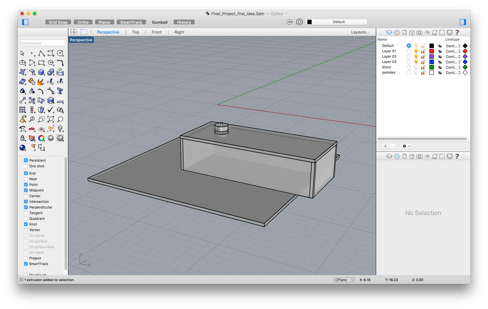
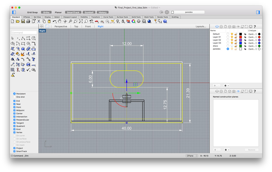
I decided that for represent my final project I should use Rhino 3D. The idea of how the 3D zoetrope would look like isn’t very clear but I could represent the basic functionality having in mind that this model could be totally changed due to possible improvements of the project.
So here is the first sketch I did before transcribing it to Rhino:
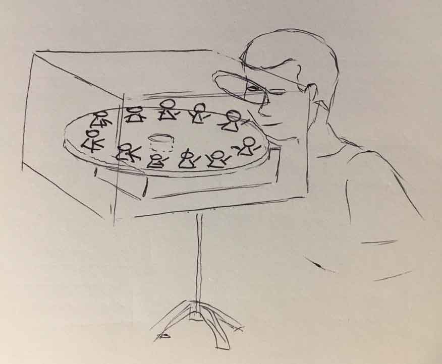
The 3D Zoetrope that I intend to build is a gyratory platform containing a series of 3D figures distributed alongside the peripheral margin of the circular base. Each figure display a sequence of a movement and depending on the velocity that the platform is rotating, our eyes will see a continuous motion coming from the figures. Keeping the whole structure in the dark will contribute to bring the receptor “closer” to the action, eliminating all possible interference out of the eye sight. I might also design a tripod or some type of holder to support the Zoetrope and keep it at an ideal distance from the receptor eyes.
It’s important to point out that while transcribing the project to the 3D software I defined that the main body of the 3D Zoetrope was going to be made with 6mm MDF. Although not visible in the simulation I plan to interlock the walls with press fit joints alongside the corner edges. I haven’t done that yet because I’m well aware that this design may change and should serve as a reference rather than a final file. But I’ll anyway demonstrate this idea of creating the interlocked walls by using another software called SketchUp by the end of this assignment.
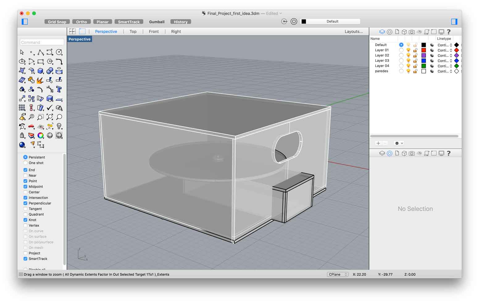
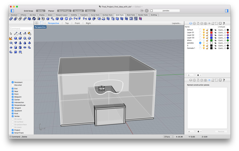
External container
I envisioned some kind of container, like a simple box whose functionality would be to hold the 3D Zoetrope and at the same time block the entry of light inside where the animation would be happening. The box would have a slit big enough to position comfortably the eyes. I probably will try out different shapes for this aperture in order to get an ergonomic design for not hurting or letting the light pass through it. There will also be a smaller box at the bottom of the container that I will call “controller” and that I’ll talk about later on.
Circular platform
Inside this box there will be a circular platform connected to a motor shaft in its middle. I’ll probably need to design some kind of accessory to better connect the motor shaft to the platform.
The main idea is that the shaft will transfer a rotational movement of the motor to the platform. The movement that will ignite the shaft is connected in some non-specified engine that will be hidden inside of a box below the platform.
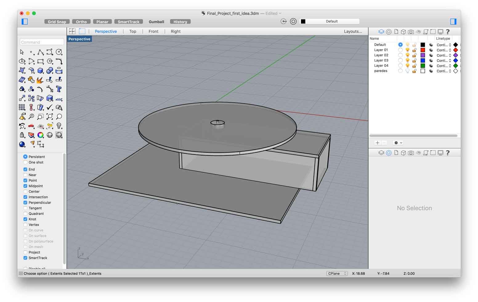
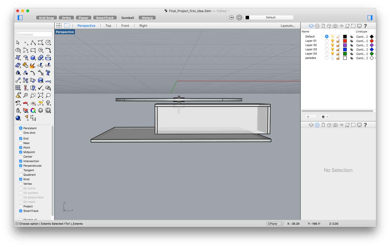
Engine/PCB container
This so called “controller” is basically a box that will keep an engine running to rotate the circular platform. The velocity of the rotation must be dimerized and not predetermined. I also envision some kind of light control inside the box. All these specificities will be registered in the PCB that I intend to build. I also extended the box outside the Zoetrope main container. This is because my intention is that the viewer will be able to control things like lightning and velocity, changing the way the 3D models will be noticed.
All this logic is yet to be done, but making this exercise of envisioning my final project helped me to better comprehend and keep in mind adjustments for all the set.
Experiment using SketchUp to build interlocked walls edges
I tend to use Sketch up when I have to create interlocked edges. This process is also possible to be completed using Rhino, but as a matter of an experiment I’ll show the steps on how to do it using SketchUp.
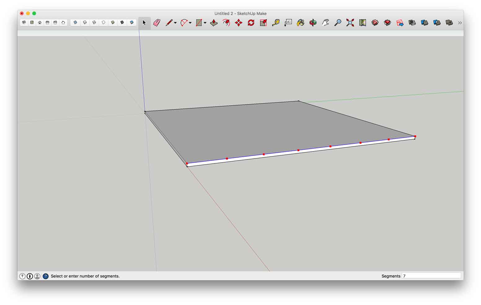
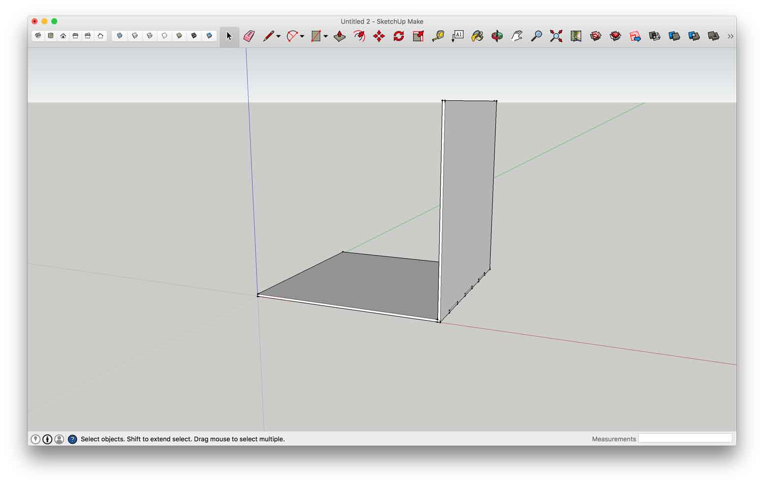
- First thing I created a random sized square and extruded it to the thickness of the 6mm MDF that I intend to use in the final project.
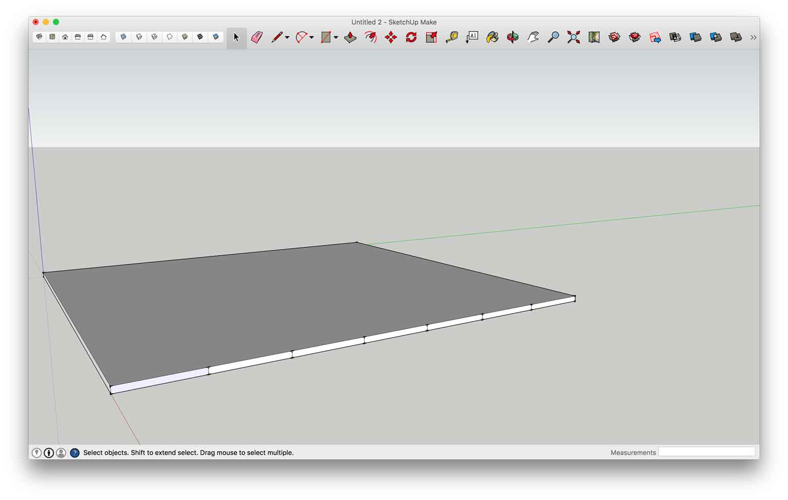
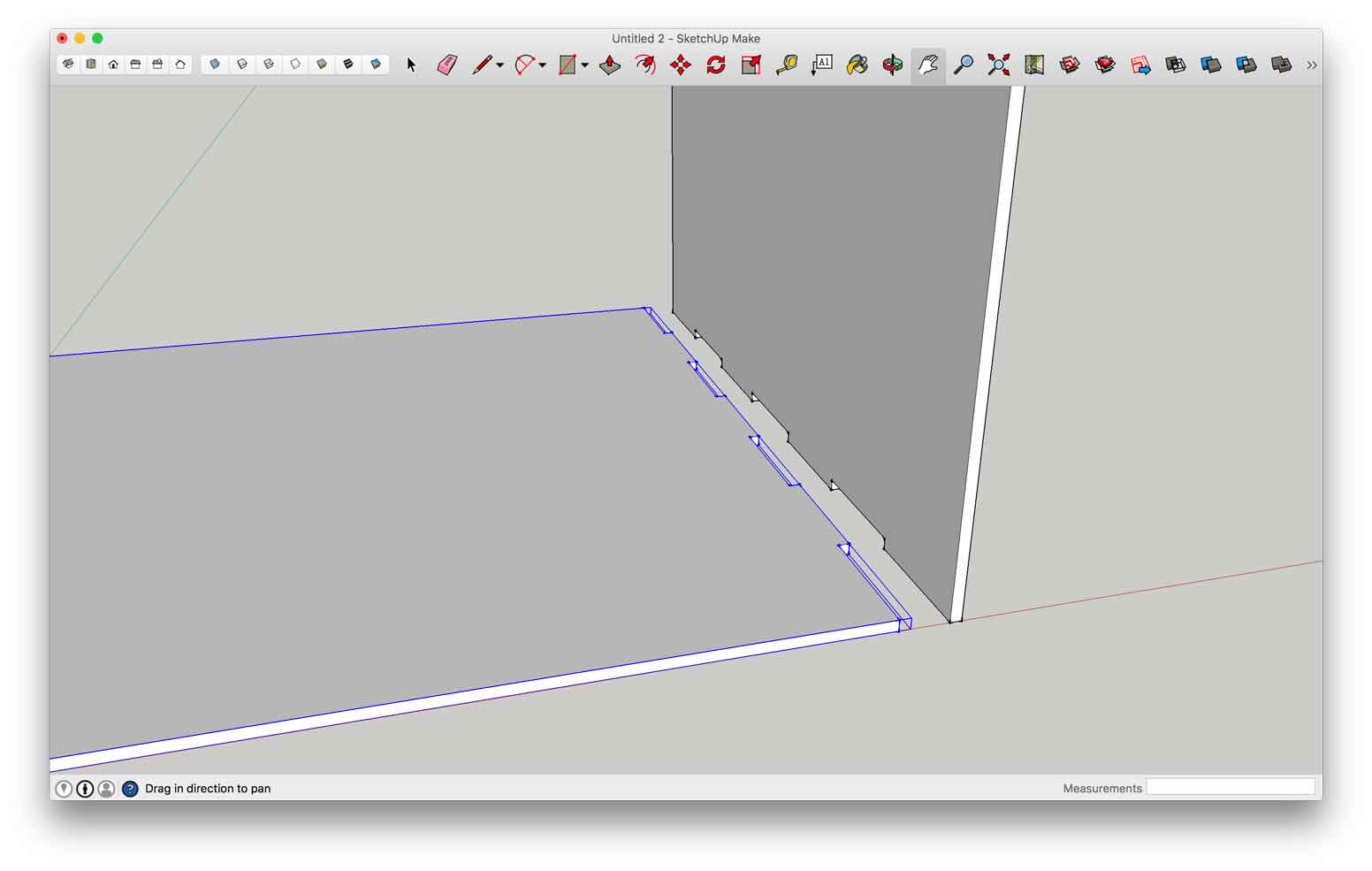
- I selected the edge of the shape I wanted to create the slots and right-clicked the mouse to select the “divide” option. This tool allowed me to divide the line in 7 segments, giving me information about the spacing between them.
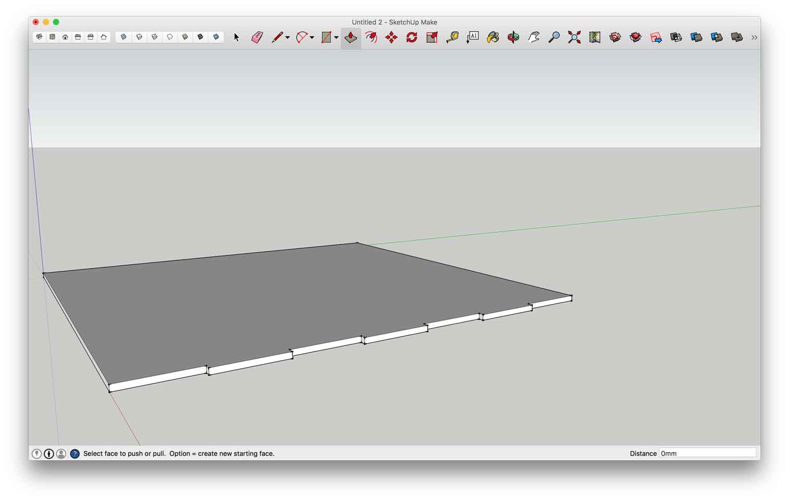
- With the “line” tool I created lines starting from the segment points crossing the material thickness. I intended to separate the face that should be interlocked according to the right measures acquired in the divide point step.
- Having all the lines done and the face separated in 7 parts I selected the “extrude” tool and created 6mm deep slots.
- I created another square and extruded it to the same thickness of the first and moved it to the final position where both should interlock to each other at a 90 degree angle.
- Having the two surfaces correctly positioned and superimposed it was time to use the “trim” tool. Doing that I automatically created the slots trimming out what was not necessary in the second surface.
Experiment using 2D vector
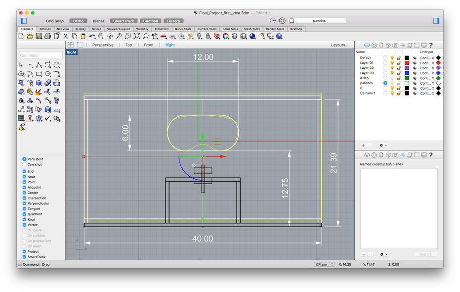
In order to demonstrate the integration between a 2D software to a 3D software I decided that the slot to place the eyes should be designed separately using Adobe Illustrator. First thing I took the measures from the Rhino drawing related to the front side of the container. Where I wanted to create the slot:
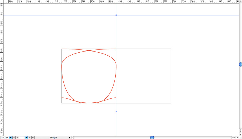
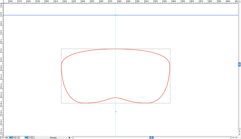
In Illustrator I used the Bezier tool to design the one half of the slot. I did this because the slot should be symmetrical and once having one side designed it’s easy to select it and mirroring it through the vertical axis:

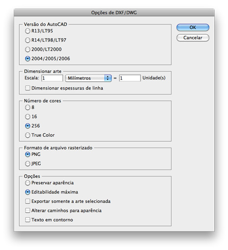
After designing the slot I exported the vector as a .DXF (Drawing Exchange Format) file:
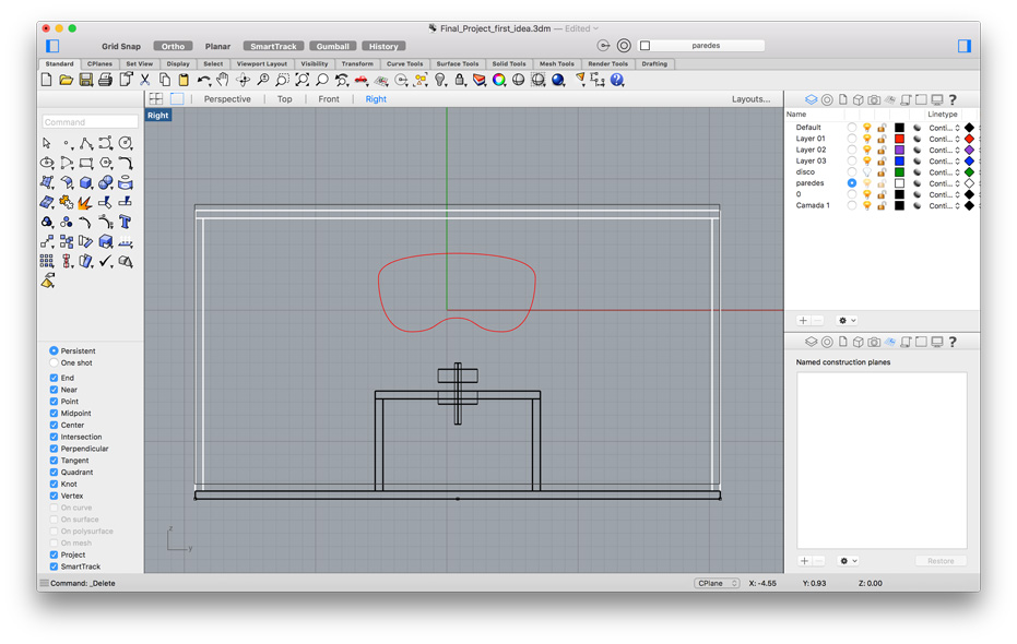
Back in Rhino I imported the .DXF file into the original file I was working on. I had no control over which view the vector would appear. But it was a matter of rotating it in order to place it in the front view aligned to the old slot:
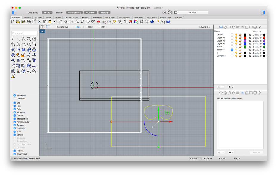
After both slots were aligned I deleted the old one as well as all the measurement references that were in the file.
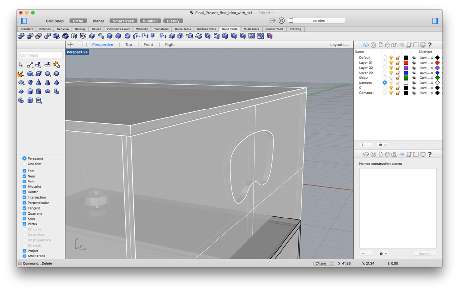
I used the “Wire Cut” file to cut through the face and create a hole with the shape that I originally designed in Adobe Illustrator:
Softwares used:
- Rhino3D
- SketchUp
- Adobe Illustrator
Files: