
Week 3. Computer-controlled cutting
During this week, I have utilized the vinyl cutter to decorate a t-shirt for my son and I have used the laser cutter to create a press-fit construction kit.

Tasks
- Make laser cutter tests parts using different settings and slots dimension (Group work)
- Cut something with the vinyl cutter
- Create a parametric press-fit construction kit
Process explanation
Using the vinyl cutter to decorate a t-shirt
My son is a big fan of pokemon, so I thought it would be a good idea to make a surprise for him to heat press a pokemon trainer's t-shirt. I utilized the vinyl cutter to cut the adequate shape in the head press vinyl. I utilized a heat press to imprint the shape in the fabric.
Understanding and setting up the vinyl cutter
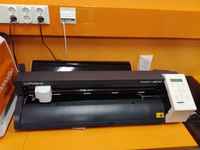
Before starting cutting anything I wanted to understand well the process and get acquaintance with the machine. Vinyl cutter operates similarly to a printer, but it has a blade which make cuts in the material instead of depositing ink on it. The material to be cut, must be provide to the machine firmware as vector graphics (I have used svg format). Vinyl cutters are widely used in the field of advertisement and in organization of big events. The vinyl cutter in our Fab Lab is a Roland GS24.
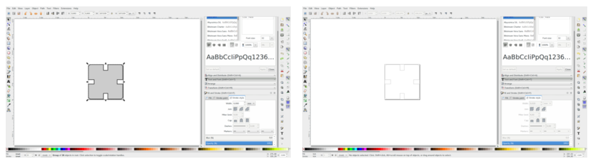
In collaboration with the other Fabacademy students we made some initial tests in order to learn how to use the machine and configure the settings. At the same time, we wanted to know how the width of the lines in the svg file affects the cut.
We created in >Inkscape three different stars with three different widths: 0.05 pt, 0.5 pt and 25 pt. All the stars where aligned at the bottom using Inkscape alignment tool (See Figure 2).

We follow the next steps to print the stars:
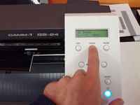
- Place and adjust the vinyl cutter roll using the lever at the left side of the machine. Be sure that the blade force (an analog slider located at the right side of the machine). We set it up to 0.
- Select the type of vinyl you are using: piece (when you are not using a roll), roll or edge (similar to roll, but you cannot adjust the origin up and down). You set the type by pressing ENTER
- Set up the origin of coordinates using the arrow buttons located at the right side of the machine. When the blade is in the right position keep pressed the origin button to store the origin.
- Prepare the svg file to be printed. The origin of coordinates should be at the bottom-left corner
- Press the print button in your software (Inkscape in our case). Open the Printing preferences choose: Cutting area > Get from machine. Change the height to the svgfile height. If you keep 1600 (the one obtained by the cutter), it will try to to move the roll 1.6 m out.
- Press Accept and print.
We learnt that when the width of the border lines are bigger than the blade, the vinyl cutter utilize a the border middle line to do the cutting.
Creating the model for the t-shirt and printing test in vinyl
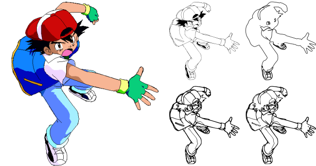
I designed the image to be imprinted in the t-shirt in a paper. The idea was to have the silhouette of Ash (the main character of the Pokemon cartoon throwing a pokeball. At the bottom should read the text: "Entrenador Pokemon", that is, Pokemon trainer in Spanish.I first search for an image of Ash throwing a ball using Google Image search engine. I chose the one shown at Figure 4, left. It was a gif file, so I had to convert it to vector graphics. To do that I opened in Inkscape and used the Path>Trace bitmap option to extract the path. I played with the different settings until i got the correct one. I just wanted the outer silhouette, so I did not need too much detail. Figure 4 shows 4 different settings. Top-left: Brighness-cutoff=0.9; Top-right: Brightness-cutoff=0.1; Bottom-left: Edge detection=0.9; Bottom-right: Edge detection = 0.1; I finally selected the one with less details (top-right).
After that, I had to remove the rest of inner details in order to extract the silhouette. To that end, I used the Edit path nodes tool. Since, the image had too many nodes (Figure 5, left. I utilized the Path>Simplify option to reduce the number of points. The result is shown on Figure 5, right. Next, I removed manually the inner paths (selecting the nodes composing the path and pressing the Delete button. I activated the Show path outline option, from the Edit path tool-bars. When this option is activated, a red line shows the paths.

When I managed to remove all the inner paths, and got the silhouette, I decided to create the Pokeball myself. The process is shown in Figure 6. The process is at follows:
- I created a semicircle using the Create circle, ellipses and arc tool. Then with the Switch to segment button at the top toolbar selected I draw a 180 degree figure.
- I created a circle, much smaller than the previous one
- I centered the circle with the semicircle horizontally: Align and distribute>Center horizontally. In the right bar I activated the Enable snapping ,
bounding boxes and snap midpoints of bounding box edges and snap center of objects. When all this is activated, it permits placing the center of the small box in the center of the semicircle. - After that, I duplicated the semicircle, rotated it 90 degrees, and mirrored it vertically. With the cursor I moved the upper figure up and the bottom figure down a pair of mm. After that I got the image at the Figure 6 centered.
- Using the Path>Difference and
Path>Exclusion operations I removed the small circle and other unnecessary lines. - After adding background color to both figures (Fill option activated in Fill and stroke menu), to visualize better the output I got the image at the Figure 6 right.
- I added the text at the bottom. I wanted that the font is the closest possible to the one using in the cartoons, so I downloaded and installed the Ketchum font.

After a few small position adjustments I got the results shown in Figure 7

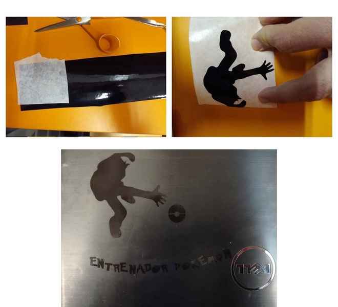
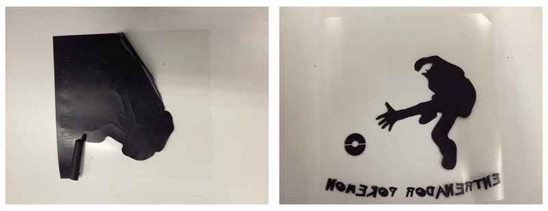
Before cutting the final version with the heat press vinyl I wanted to check that everything was correct. So, I utilized first normal black vinyl. I followed the same instruction as in the previous section. Removing the vinyl from its support material is not an easy task. I utilized a tweezer and transfer paper. I attached the transfer paper firmly against the vinyl. Push hard with my hand, and after a while I removed it slowly. In some cases, I had to use the tweezer to unstuck some parts that where not attached to the transfer paper. Once I got it out i sticked it in my laptop. The process is shown in Figure 8
Cutting and Heat press to the t-shirt
Finally, everything was ready for the heat press. I first MIRRORED THE IMAGE so it looks correctly when it is imprinted. This is specially important for the text, otherwise it would look up side down. I did that using Inkscape Flip horizontal option. When I got the correct file, I load the heat press vinyl in the machine. It has two different sides, the matte side and the glossy side. The matte part should be the part to be cut (it is the part that sticks in the t-shirt). The glossy part is used as a protector while applying the heat.
The first cutting attempt was a failure. I did not check before hand and the blade did not have enough force to cut the material. Hence, I had to retry the printing, applying a little bit more force (using the analog slider on the right of the vinyl cutter). The second attempt was successful. I only had to weed the leftover material and the result is shown in Figure 9
The final step is to put the t-shirt on the heat press. The heat press vinyl on top of it (with the glossy part facing up), set the temperature of the machine to 160 degrees and a time of 20 seconds, and apply the heat. I checked that it was correctly attached to the fabric, and removed the glossy layer. Tachan!!! a nice and unique Pokemon t-shirt

Model, create and design a parametric press fit kit
Simple model using Freecad
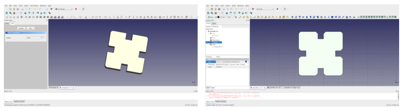
After trying different configuration settings with my colleagues I decided to build a simple parametric press fit piece to be laser cut out of a 4 mm acrylic. I chose Freecad as a modeling tool. The final result are shown in Figure 11. They are quite similar but the one on the right has a chamfer in the slots borders.
The process I followed to create this pieces with Freecad is as follows:
- I opened the sketch workbench and create a new sketch
- I used the polilyne tool to build the sketch of my model. I did not worry that much of the measures and the constrains (Figure 12 left
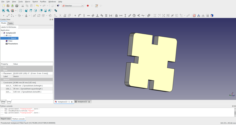
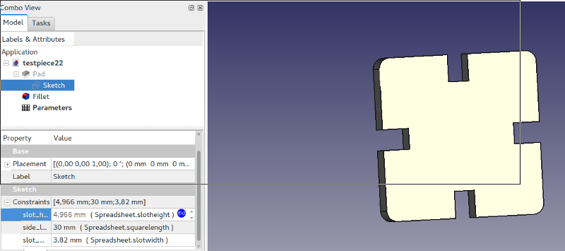
- Once the figure is built, I just provide three different measures: the side length of the square (30 mm), the slot width (4mm => material thickness) and slot heigth (6mm). Selecting those constraints from the Constraints box I set a name to identify these three measurements. They are going to be part of my parameters.
- After given the measurements I applied the equality constraints to the corresponding measurements. That is: the 4 slots had the same width and height and the 4 sides of the square had the same length. The result is shown in Figure 12 right
- Next, I closed the sketch, changed to the Part design workbench and utilized the Pad tool in order to extrude the sketch 4mm.
- Next I applied a fillet of 1mm to the four corners of the square (Figure13)

We wanted a parametric piece. Parameters that I decided to can be modified are: Material thickness, Kerf, square size and slot height. The slot width would be the thickness of the material - kerf. I created a Spreadsheet to define the values of the parameters using the Spreadsheet workbench. The first column shows the name of the parameters while the second column contains the values. Next, in order to refer to these parameters in the constraints, I had to create aliases for the corresponding spreadsheet cells. (Figure 14).
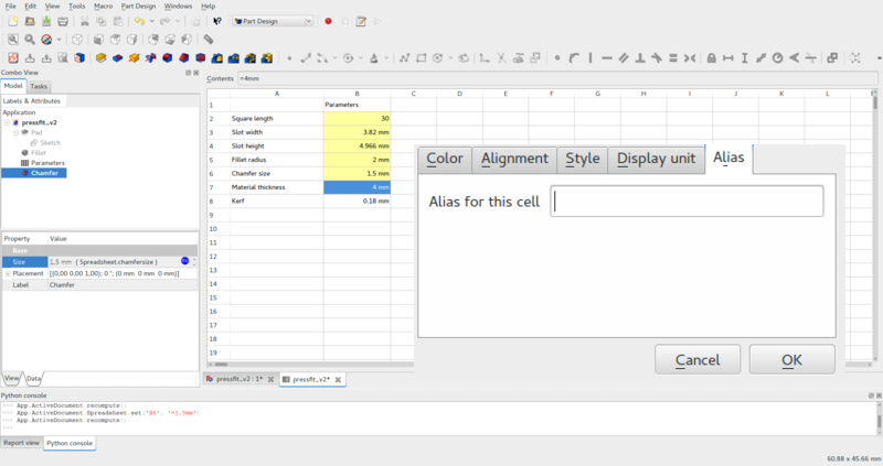
Next, it is necessary to link the constraints with the parameters values. I went back to the sketch view, and in the model window>Data>Sketch constraints are solved. I selected each constraint, pressed the fx symbol and wrote there the alias of the parameter: Spreadsheet.alias (Figure 15 ). Now the geometry is fully parametrized.
During the following step, I exported the geometry to svg format. I followed two different methods:
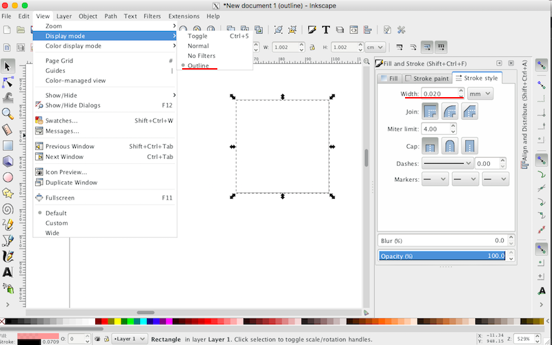
- Utilizing the Drawing workbench, I selected the top face of the object, pressed the Insert new drawing button and then insert an orthographic projection viewed from the z plane.Finally, from the main Menu select export as flattened svg (Figure 16). After that, I had to use Inkscape to remove fillings and apply adequate line width (0.02mm). The problem of this solution is that, at least in my case, drew three times the same line, one over another, so the laser cutter went 3 times through it.
- The second option was using the Create 2D views on selected objects from the Draft workbench. It just created a projection of the object on the base plane. Just select the projection and export as svg. This option turned out to be much simpler and quicker than the previous one. It needs some adjustments in Inkscape, though (Figure 17).

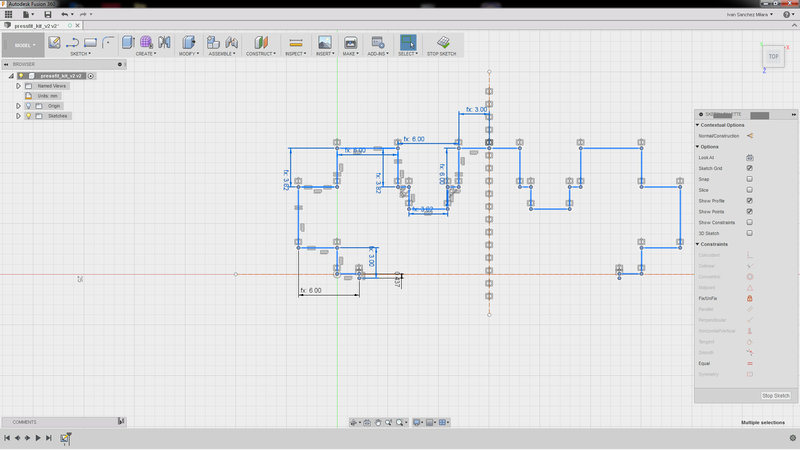
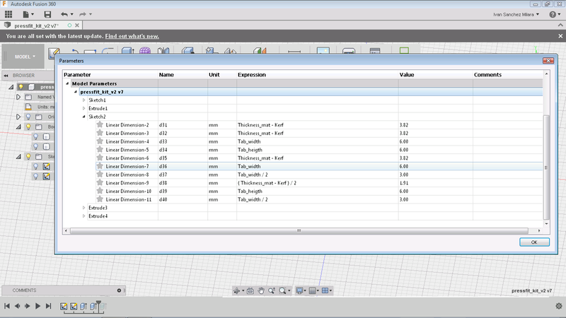
More complex version utilizing Fusion 360
I designed a piece in two pieces can fit together either in vertical or horizontal position. No time to explain but here are the screen shots of the process. I will document with much more detail later.


Cutting and testing the press fit kits
Here are the results after cutting the 3 pieces. Note that the initial kerf that I used (1.85 mm) was not enough. I had to increase the kerf til 0.21 mm in order to ensure good fitting.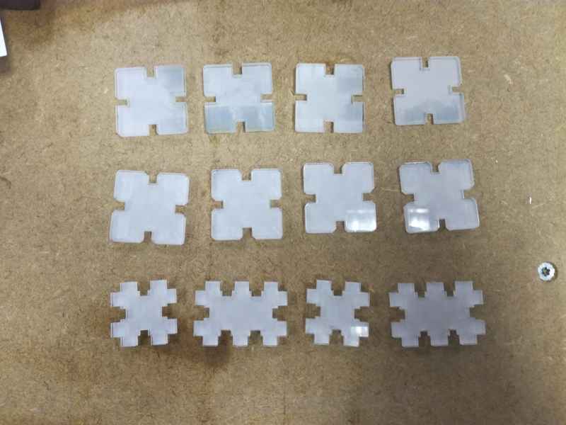

Create test parts for the laser cutter (group)
My colleagues at the lab should have all related information. We have been working with different laser cutter configuration settings and checking the kerf. For instance, Nataliya Shevchuk's description of week 3 includes a detailed description of our group work. It is difficult to specify who was doing what since Jari Pakarinen, Natalia Shevchuk and me worked together to accomplish the task.
Basically, the goal of the group work was to calculate the kerf of our laser cutter (a Epilog Engraver WinX64 Fusion). Roughly speaking the kerf is the groove or slit created when the laser cuts any material. When the laser cuts some part of the material desintegrates somehow (e.g. transforming it into powder). This makes the pieces are a little bit smaller than the original design. In the group work we had to define the kerf of the machine and how different settings affect the material. The kerf is important when working with press fit solutions. If you do not consider the kerf the tabs are not big enough, so they do not adjust correctly and the piece do not fit correctly.
In order to calculate the kerf, we created in Inkscape a 10 mm square. After that we cut in a 3mm green acrylic stock utilizing the laser cutter. We modified the cutting parameters to understand how different parameters affect the cutting. Finally, we measured the size of the cut square. The difference between the original size (10mm) and the cut piece would be the kerf.
NOTE on 10.06.2017: After reviewing the documentation I realized that we did one thing wrong. For measuring the kerf we should have measured the size of the cut squarers and the size of the hole left in the material. The kerf is then calculated as follows:
(Size of the square - size of the hole)/2
Fortunately, we have still the original pieces that we used for cutting, so I will update the documentation at the end.
The process to measure the kerf was as follows:
- Create a 10mm square in inkscape.
- Transform the svg file into pdf
- Put the stock in the laser cutter. In this case, it was a 3mm acrylic.
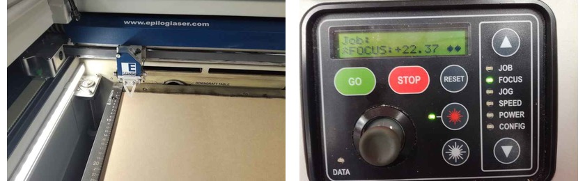
- Calibrate the focus. The laser must be to certain distance of the stock in order to be able to apply adequate power in order to cut. There is a manual calibrator that you place on the laser head (Figure 29 left). Then using the cutter's UI interface, you select FOCUS using the up and down arrow (Figure 29 right). After that using the jostyck you move the stock material up and down. The material must be in contact with the tip of the calibrator. When this happens press the joystick down in order to save the calibration.
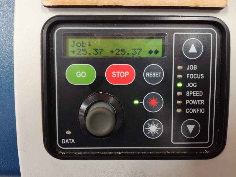
- Settings the origin. It determines which is the upper left corner of your cutting model. Using again the cutter's UI, you select JOG from the UI utilizing the up and down arrow. Then you can use the joystick to move the laser head and place in the origin. You might want to press the red button on the UI so a visible laser light is shown on the stock marking the current origin.
- Send the previous generated pdf to print. Press settings in order to open laser's cutter driver.
- In the computer's laser cutter driver set adequate settings:
There are three values that can be modified:
- Speed: How quick the laser moves through the material. Slower speeds makes deeper cuts on the material. Too slow lasers might burn the stock.
- Power: The power of the laser beam. More power means it cuts deeper in the material. Too much power might burn the stock.
- Frequency: The frequency of the laser pulses.
As a base for the settings we utilized the one recommended by the laser cutter manufacturer:
 Figure 31. Recommended settings for acrylic
 - Accept the settings and set to cut. In the laser cutter press the GO button

We modified the speed from 5% till 15% (recommended value was 9%). We did not modify the power or the frequency. The following table presents he measure of the squares (and after the documentation update also the measures of the holes)
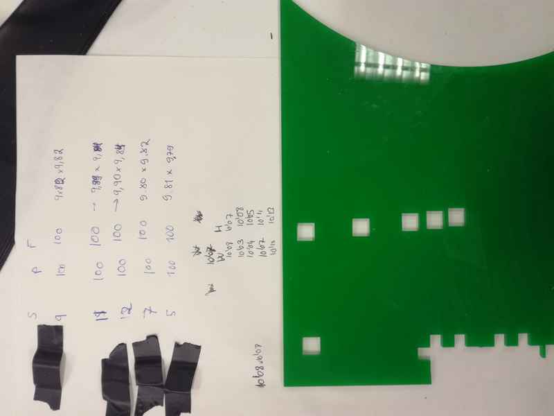
| Speed | Power | Frequency | Square Measures (mm) | Hole measurements(mm) | kerf |
|---|---|---|---|---|---|
| 5 | 100 | 100 | 9.81 x 9.79 | 10.13 x 10.13 | 0.16 - 0.17 |
| 7 | 100 | 100 | 9.80 x 9.82 | 10.07 x 10.11 | 0.13 - 0.15 |
| 9 | 100 | 100 | 9.80 x 9.82 | 10.08 x 10.07 | 0.13 - 0.14 |
| 11 | 100 | 100 | 9.89 x 9.84 | 10.03 x 10.08 | 0.07 - 0.12 |
| 12 | 100 | 100 | 9.90 x 9.84 | 10.04 x 10.05 | 0.7 - 0.10 |
| 13 | 100 | 100 | Not cut | Not cut | Not cut |
| 15 | 100 | 100 | Not cut | Not cut | Not cut |
From these settings we know that the maximum speed in order to cut the acrylyc would be 12%. Upper values wont cut the material. In addition based on the initial calculations we got that the kerf was between 0.15mm and 0.10 for this material. Note that we used a digital caliper to measure the size of the square, so errors might rise.
Mikko Toivonen worked in another method to calculate the kerf. Basically, he built several comb like models, in order to fit one with another and check which is the combination that fits better. The advantage of this method is that we avoid the errors added by the measures themselves.
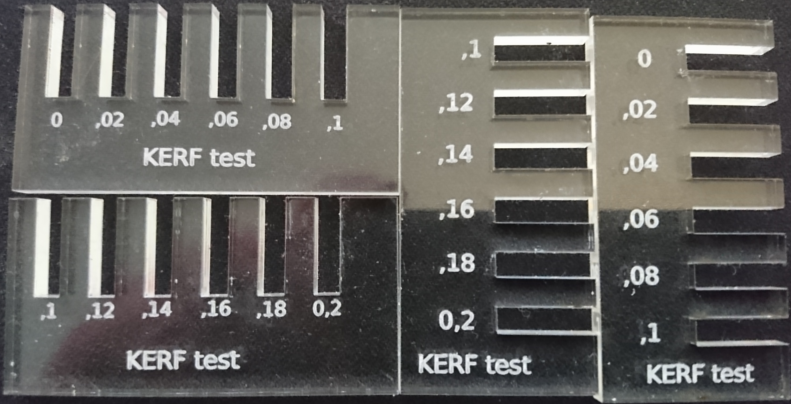
Based on his model, we got that the kerf for this material and this laser was 0.18 mm
NOTE on 10.06.2017: I added the size of the holes in the previous table and make a new calculation of the kerf. We made a mistake while measuring the kerf and we did not considered the size of the holes. With this new method the kerf was between 0.16 and 0.07 mm. We noticed also that as we increase the speed, the kerf was reduced. So, KERF depends on speed. Anyhow, when I created the press-fit I had to use a kerf of 0.21, so it is important to always measure the kerf with the current settings and material that you are using.
Resources utilized
- Inscape: a multi-platform open-source vector graphics suite. I created the model for the vynil cutter with it.
- Roland GS24: Our Fab Lab's vinyl cutter
- Heat press: To imprint the heat press vinyl in the t-shirt.
- Epilog Engraver WinX64 Fusion: Our Fab Lab's laser cutter
- Freecad: a parametric 3D modeling tool
- Fusion 360: a cloud based parametric 3D modeling tool
Reflection
Summary
During this week I learnt how to use the vynil cutter and the laser cutter. I learnt also how to make press fit pieces that fits without need of glue.
Main difficulties
For the press fit is crutial to calculate correctly the kerf, otherwise the pieces won't fit. It took me a few cuttings attempt to make the pieces fit correctly together.
Inkscape and our vynil cutter did not understand really well each other. If you did not use the correct settings, the vynil cutter made strange things, for instance, rotating the models 90 degrees. I had to repeat a few times the cutting until I got the right settings.
Main learnings
Laser cutter is by far the most utilized machine in our Fab Lab. Some times we had problem to find slot available to make our tasks. Hence, it is important to reserve the machines well beforehand if you wannt be sure that you can finish your work on time.
Test the vinyl and laser cutter settings using some simple small models (e.g a small square) before cutting, is really important in order not to waste material.
Models files
- Vinyl cutter design:svg format
- First design in Freecad: fcstd and svg format
- Second design in Freecad: fcstd and svg format
- Third design in Fusion 360: f3d and big piece in dxfformat and the small piece in dxfformat