
Week 13. Input devices.
During this week i have fabricated a simple board which is able to read data from a Ultrasonic Sensor Module
Tasks
- Add a sensor to a microcontroller board that you have designed and read it
Process explanation
Overview
Sensors
Ultrasonic Sensor Module
Ultrasonic Sensor Module design and fabrication
The PCB should work as follows:
- A user sets a threshold (from 10 cm to 4 m) using a knob (potentiometer)
- The Ultrasonic module starts measuring distance to the nearest obstacle
- When the distance is less than the threshold the LED start blinking/turns on and a buzzer start beeping. It stops if the distance is again bigger than the threshold
- An FTDI serial connection is used to debug the code. The values read from the sensor and the current value of the threshold is sent periodically through the serial port.
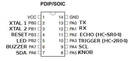
Let's analyze the needs for my circuit from the microprocessor point of view. I am using a ATTiny 44 microcontroller. The HC-SR04 ultrasonic sensor module needs two different inputs: one digital output and one digital input. The buzzer / LED needs a PWM output, while the knob (potentiometer) needs one analog input .The FTDI cable needs one digital input and one digital output. Finally, if possible I would like to have the two I2C pins of the ATTiny 44 (SCL and SCA) available so it can be connected to other modules in the future. Figure 2 shows the pinout of the ATTiny44
Bill of materials
- ATTiny 44 microcontroller
- Red Power LED
- Orange LED
- Buzzer
- HC-SR04 (ultrasonic sensor module)
- One potentiometer (trimmer or knob) E
- Pin headers for the SPI (6) and FTDI (6)
- Batteries
- Resistors and capacitors
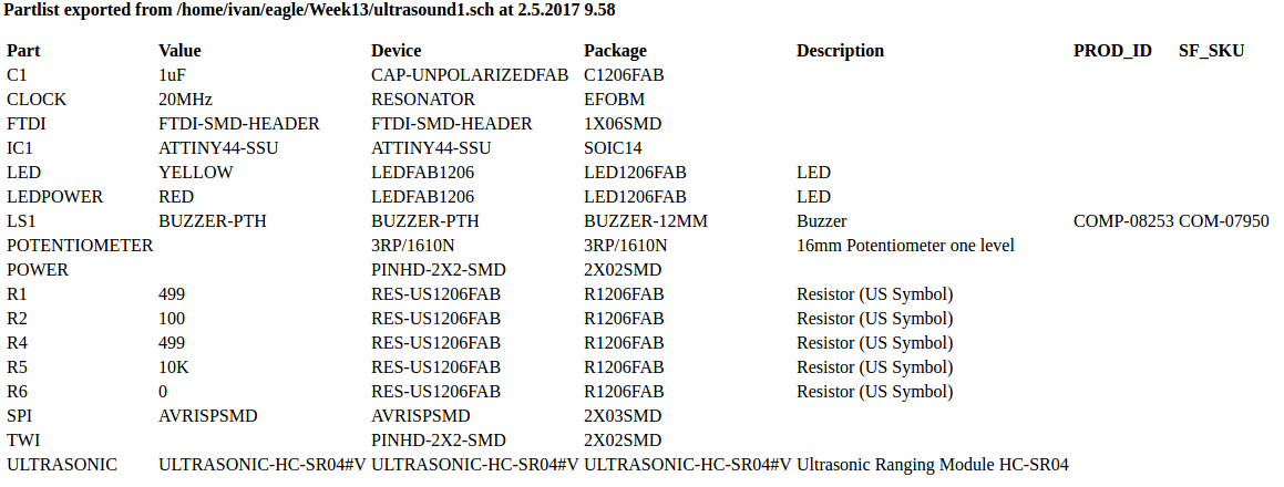
Complete Bill Of Materials is shown in the following figure
Eagle design and fabrication
Schematics were built using Autodesk Eagle 8.1.1. I utilized a similar approach as in Week 6.I had to download some libraries for some eagle components:
- DIY modules for HC-SR04
- Sparkfun libraries (Electromechanical.lbr) for Buzzer (CEM-1203)
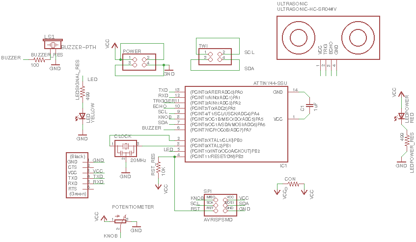
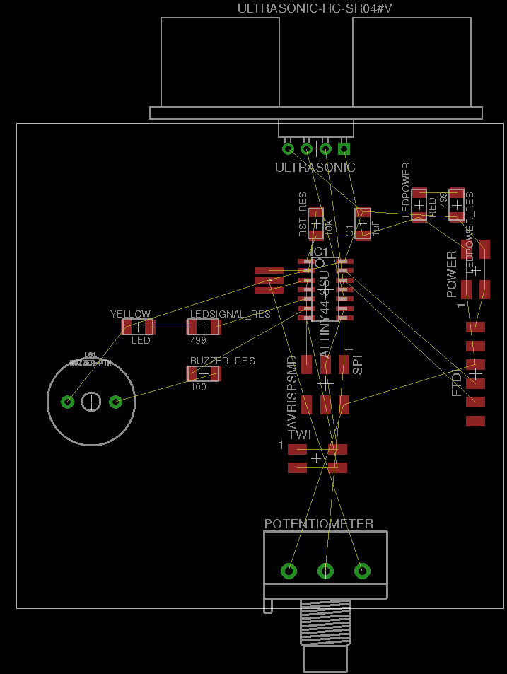
In addition I used the Pot library coming in Eagle to draw the 16mm Potentiometer one level, (that is the knob). Figure 04 shows the schematics diagram.
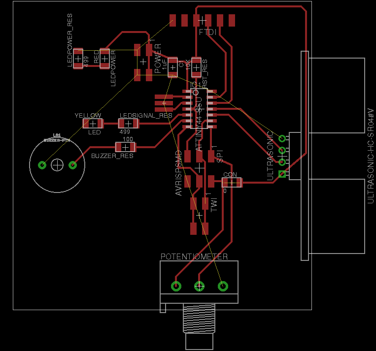
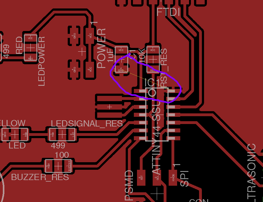
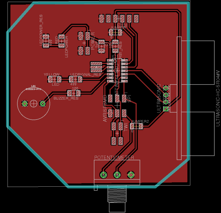
I build the board file using the same procedure as in Week 6. In addition, I created a Ground plane as explained in Week 10. All the track widths are 0.016 inches. I utilized a grid size of 0.025 inches and a Alt resolution of 0.005 inches. . I had to adjust the dimensions (adjusting the sizes of the lines from the Dimension layer) of the board so the ultrasonic module, the FTDI headers and the knob are placed at the border of the board. Figure 5 to 10 shows the whole process. I had to made some modifications in the position of the components during the design. The most remarkable ones are the position of the FTDI header and the position of the Ultrasonic module, so the tracks does not cross each other. In addition, as shown in Figure 7 I had to add a new jumper (0 Ohm resistor) to connect two ground planes disconnected. I had also to increase the size of the ground plane to include the VCC track at the top right of the figure (See Figure 8)
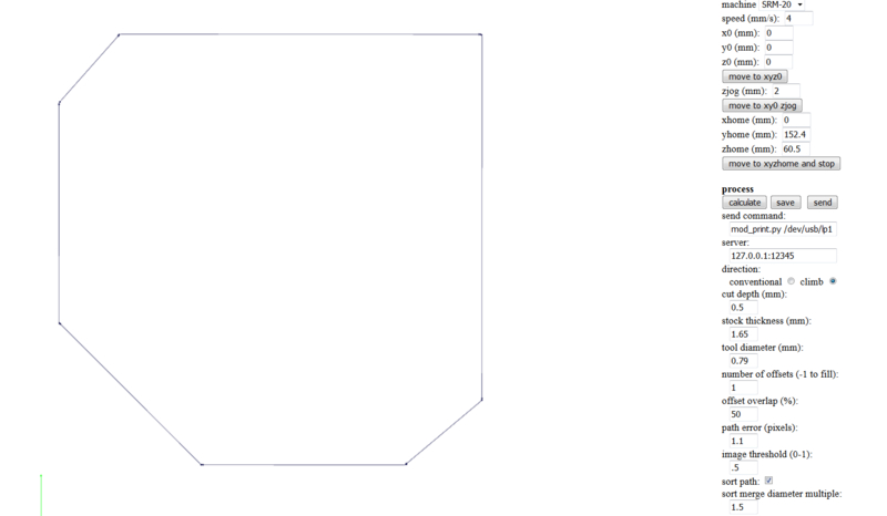
The outer border for cutout was drawn with 0.04 inches lines in the layer 46: Milling.
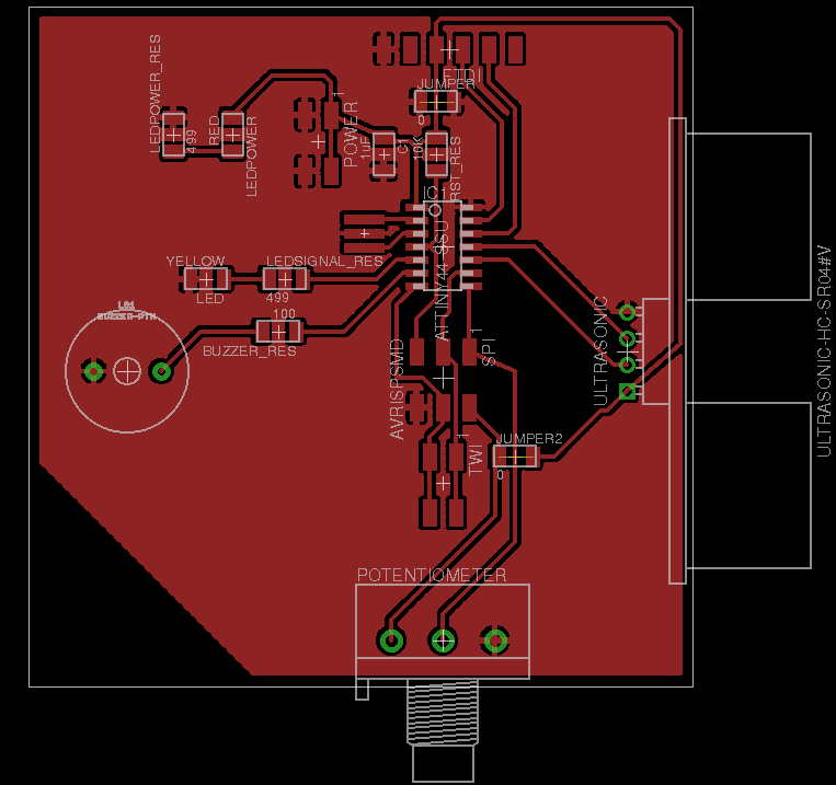
Final version of the board is shown in Figure 09
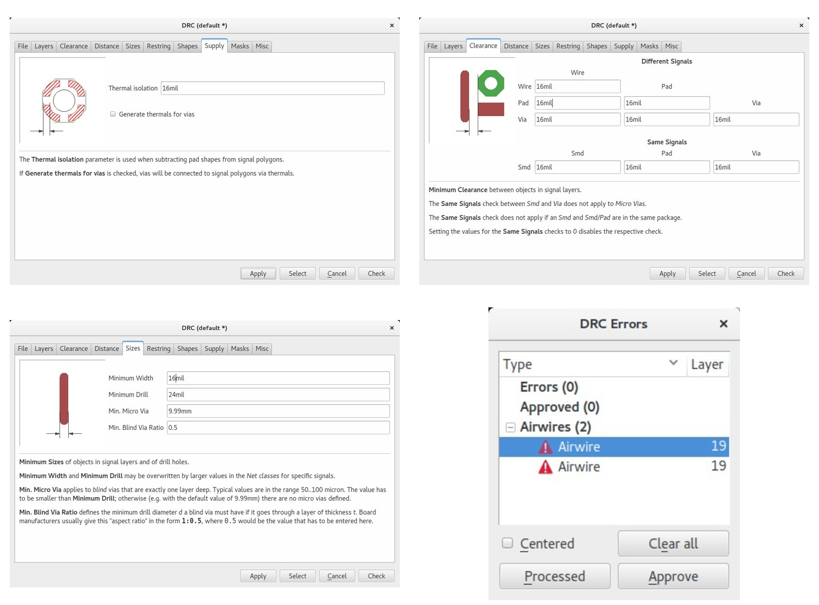
Then I run the DRC with the settings shown in Figure 10. The test run OK (see result on Figure 10 bottom-right). Note that the Air Wire errors comes from the jumpers (0 Ohm) placed to connect Ground and VCC
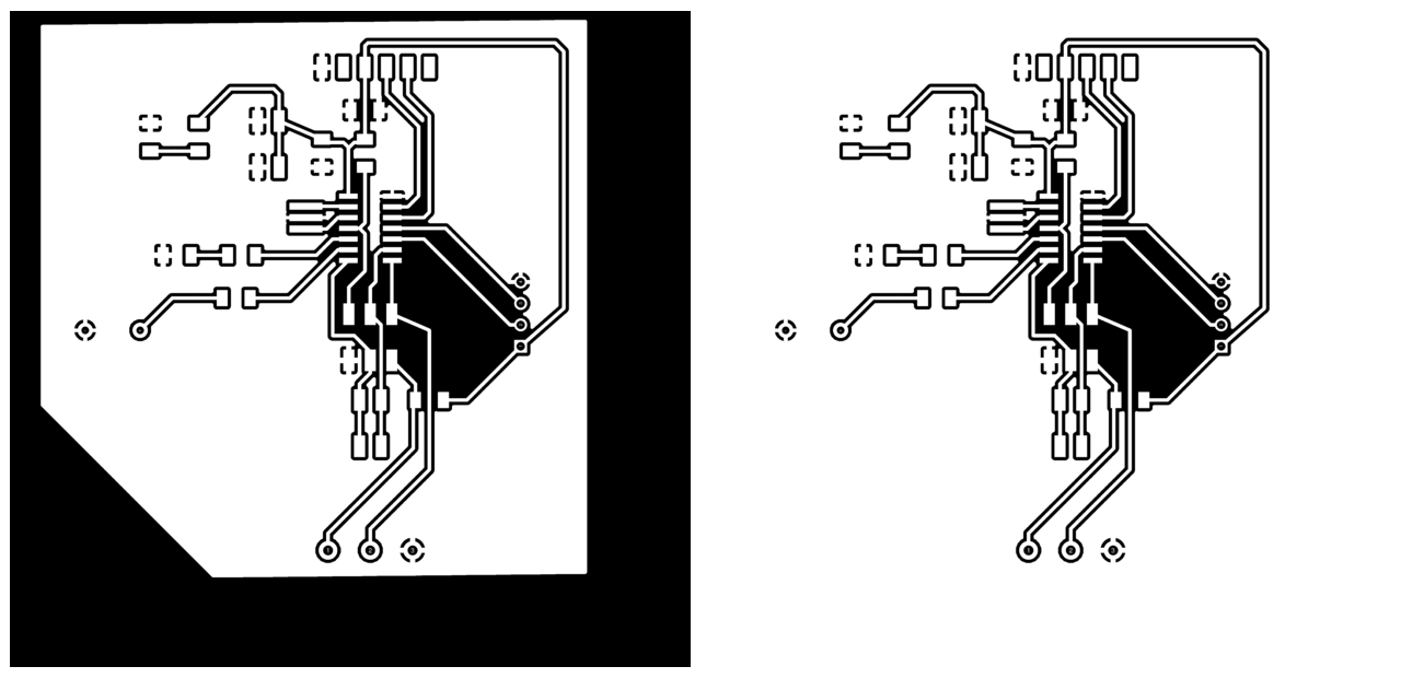
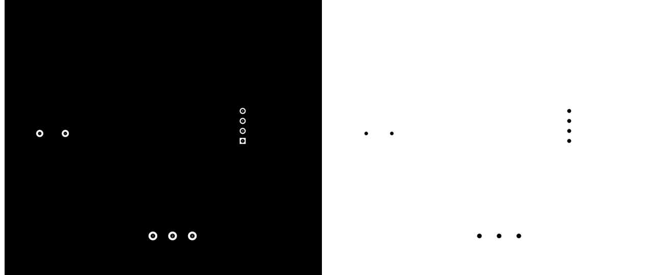
When creating the .png file to be sent to FabModules it is important to remember certain aspects. For example, since I have some hole mounting pieces, the traces file should include layers Top: 1 and Pads: 17. The .png file was exported with a resolution of 1500 dpi to monochrerome using a black background. On the other hand, the outline (layer 46: Milling) was exported with with a white background. The holes, we exported using a black background and using only (layer 17: Pads).
Finally, I had to use GIMP's fill tool to provide proper background color to the pictures borders. I had also to remove some text appearing on some of the holes with the same tool.

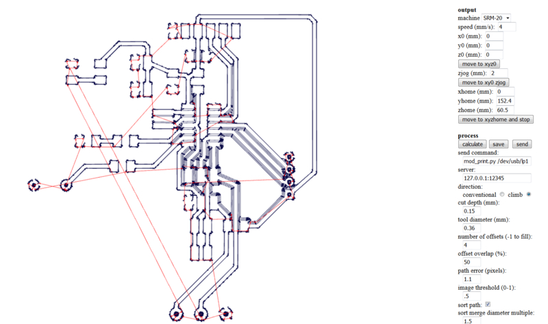
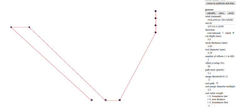
After that I used Fabmodules to transform the .png file into Roland .rml format, that is, to get the toolpath. The settings and procedure is the same as the one explained in Week 4. Following figures shows the settings for the three different .rml files: traces, holes and outline. While doing the traces I had to change the tool diameter from 0.4 mmto 0.36 mm, otherwise some of the paths could not be drawn. This might be due to the fact that I used too small track width (0.016 inches). A width of 0.024 or even 0.038 would have been much better for this purpose.
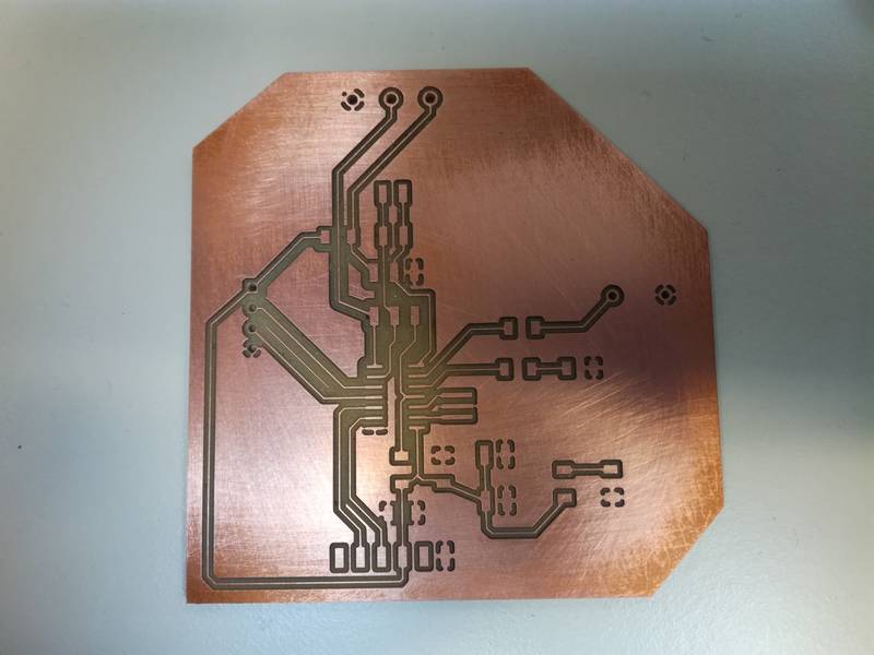
After milling the board with the Roland-20 I got the board on Figure 17. Some of the lines are really thin, I hope they are OK to finish the project. Otherwise, I will have to mill it again tomorrow using wider tracks (e.g. 0.024 instead of 0.016)
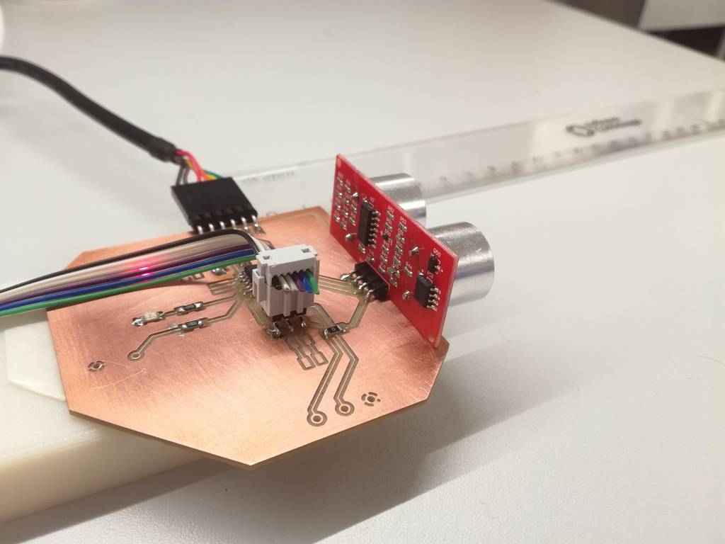
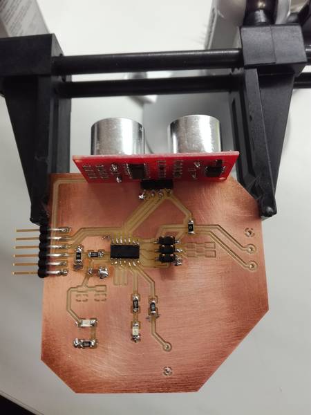
After stuffing and soldering the PCB looks like in Figure 18. I decided to solder the Buzzer and the Trimmer later, when I checked that the board is working correctly. I checked for shortcircuit using the multimeter but I could not find any.
Ultrasonic Sensor Module coding
I decided to test the different parts of the circuit sequentially. I created 4 different applications:
- A small program to test if the serial communication port works
- A program that is able to read the distance from the Ultrasonic sensor module and send it to the computer via serial port
- A program that turns a LED on when the distance measured is smaller than a hardcoded threshold
- A program that behaves like the previous one but allows to define a threshold using the potentiometer in the board.
Before starting writing code I checked that the microcontroller could be programmed. As explained in week 8 I utilized the Raspberry Pi as programmer. I connected the FTDI cable to the Raspberry Pi and the PCB to power it, and I connected the SPI interface to the Raspberry Pi. Then I executed the Verification command from avrdude. It succeeded
sudo avrdude -p t44 -P usb -C ./avrdude_gpip.conf -c rasp_pi_1

avrdude: AVR device initialized and ready to accept instructions

Reading | ################################################## | 100% 0.00s

avrdude: Device signature = 0x1e9207 (probably t44)

avrdude: safemode: Fuses OK (E:FF, H:DF, L:62)

avrdude done.  Thank you.
The sensor works as follows:
- You send a pulse of 10 microseconds through the sensor Trigger pin (connected to PA3 in the ATTiny
- The Echo pin from the sensor send a pulse which width is proportional to the distance measured. Measuring the pulse duration we can calculate the distance through the formula:
distance = pulse_width * velocity (340M/S) / 2
If we consider distance in cm and pulse width in microseconds we have:
distance (cm) =(pulse_duration(us)/2) / 29.1
pulse_duration (us) = counter / 8 (->frequency: 8Mhz, 8.10^6)
HENCE
distance(cm) = (counter/8)/58 = counter/464 => counter = d(cm)*464
Testing the serial port connection
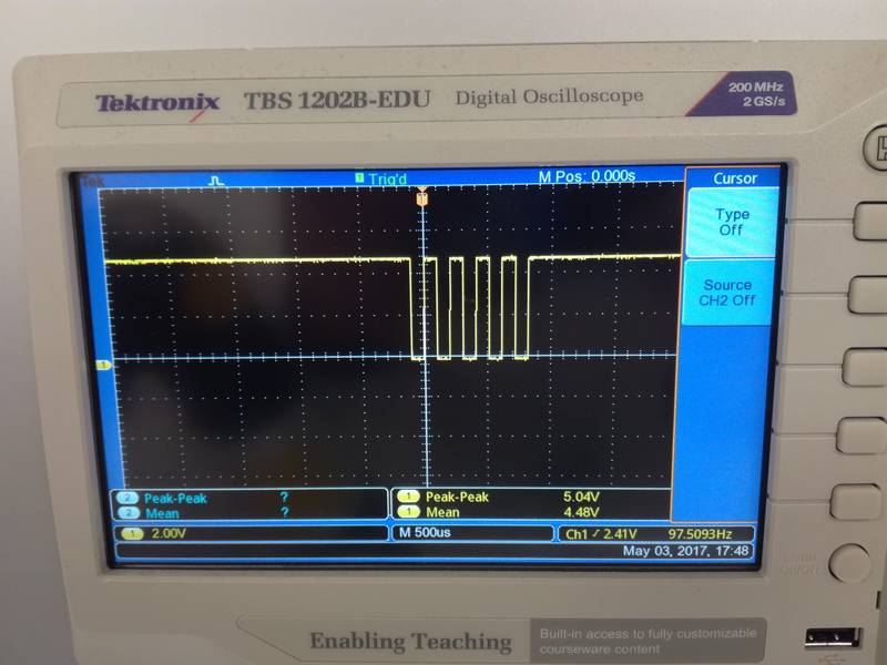
The testing serial connection application is just a simple program that sends some text to the computer, via the serial port built in the FTDI, every 4 seconds. I run the application test_serial_communication.c using the test_serial_communication.c.make but I could not make it work. The serial port in the PC did not receive any message. I test the TX signal using the oscilloscope (Figure 19) and it seems correct, so it might be a problem from the serial port in my computer. I need to investigate further this issue. I utilized the
sudo miniterm.py /dev/ttyUSB1 9600command to start a serial communication between the board and the Raspberri Pi.
I discovered two main problems in my board:
- First, I misunderstood the concept of Tx and Rx pins from the FTDI pins. I was thinking that input and output were relative to my microcontroller so I was writing data through the Tx pin and reading data through the Rx pin. Actually, the reference is the computer (in this case the Raspberry Pi) and not the microcontroller so the pins were changed. Thanks to Bas for the tip.
- One of our Fab Lab assistants (Antti Mäntyniemi) helped to solve another problem. Actually, it was just a shortcircuit in the Rx pin of the board. After solving this issue and running the
sudo miniterm.py /dev/ttyUSB1 9600
I got it up and running.
ivan@ivans-pi:~$ sudo miniterm.py /dev/ttyUSB1 9600
[sudo] password for ivan:
--- Miniterm on /dev/ttyUSB1  9600,8,N,1 ---
--- Quit: Ctrl+] | Menu: Ctrl+T | Help: Ctrl+T followed by Ctrl+H ---
␀
Testing FTDI output.
Testing FTDI output.
Testing FTDI output.
Testing FTDI output.
Testing FTDI output.
Testing FTDI output.
Acutally I run three different tests:
- Sending periodically the byte 01010101 so the output is easily captured by the oscilloscope
- Send just one character and a new line
- Send a completely string
Sending distance through serial port
Serial connection did not work so I could not perform this task
UPDATE: 22.05.2017I managed to get it working after solving the previous issues. In this case, since I am using the external clock of 20 MHz, the calculations to make the transformation to distance is a little bit different. In addition I decided to change the scale of the counter, since with 20MHz, and utilizing just two bytes for the counter the max distance range is reduced considerably. Hence, I decided to scale the clock by 8. Hence, the counter frequence is 20MHz/8 = 2.5 MHz. To do this change I just had to set the second bit of the TCCR0B register.
TCCR0B |= (1 << CS01); // prescale /8
The formula to calculate the distance change a bit with respect to the given in the previous section:
                    distance (cm) =(pulse_duration(us)/2) / 29.1 (see http://www.instructables.com/id/Simple-Arduino-and-HC-SR04-Example/)
                    pulse_duration (us) = counter / 20/8 (->frequency: 20Mhz, 20.10^6 ; preescaler=1/8)
                    SO-> d(cm) = (counter/20/8)/58 = counter*8/1160
The counter had only 8 bits. However, detecting the counter overflow, we can add an extra byte. Everytime the counter reaches its limit (that is, 255), we increase a second byte in one unit. In that way, we have a counter of two bytes (can reach values till 65536). The code was obtained from the lecture material
                    char high = 0;
                    char low = 0;
                    if ((TIFR0 & (1 << TOV0)) != 0) { // check for counter overflow
                      high += 1;
                      if (high == timeout)
                         break;
                      TIFR0 |= (1 << TOV0);
                      }
                    }
And hence, the effective counter value and the distance can be calcualted as:
                    counter = 256*high + low;

                    //FORMULA=> distance (cm) =(pulse_duration(us)/2) / 29.1 (see http://www.instructables.com/id/Simple-Arduino-and-HC-SR04-Example/)
                    //          pulse_duration (us) = counter / 20/8 (->frequency: 20Mhz, 20.10^6 ; preescaler=1/8)
                    //          SO-> d(cm) = (counter/20/8)/58 = counter*8/1160
                    //

                    distance = counter*8/1160; //cm
I initially defined the counter as a unsigned int, but it gave a problem when tried to do the multiplication by 8. Hence, I changed to long to solve the issue.
In addition, I add some extra code to detect the overflow of the higher byte:
                      if (high == timeout && low == 0){
                         put_string(&serial_port, serial_pin_out, "Object out of range");
                         put_char(&serial_port, serial_pin_out, 10);
                         _delay_ms(1000);
                         continue; //The main loop, do not show anything

                      }
After that, I had to transform the distance (int) to char[] in order to send it through the serial port. I utilized the itoa function to that end. After that, I utilized the putstring() function provided during the lecture to send data to the computer:
                    put_string(&serial_port, serial_pin_out, " Distance:");
                    char distance_char[5];
                      // convert distance to string [buf]
                    itoa(distance, distance_char, 10);
                    put_string(&serial_port, serial_pin_out, distance_char);
                    put_string(&serial_port, serial_pin_out, " cm");
                    put_char(&serial_port, serial_pin_out, 10); //New line
The output from the serial port looks like:
                      High:14 Low:14 Counter:3598 Distance:24 cm
                      High:33 Low:112 Counter:8560 Distance:59 cm
                      High:32 Low:135 Counter:8327 Distance:57 cm
                      High:33 Low:203 Counter:8651 Distance:59 cm
                      High:33 Low:10 Counter:8458 Distance:58 cm
                      High:34 Low:78 Counter:8782 Distance:60 cm
                      High:32 Low:217 Counter:8409 Distance:57 cm
                      High:33 Low:10 Counter:8458 Distance:58 cm
                      High:11 Low:55 Counter:2871 Distance:19 cm
                      High:34 Low:87 Counter:8791 Distance:60 cm
                      High:12 Low:234 Counter:3306 Distance:22 cm
                      High:10 Low:59 Counter:2619 Distance:18 cm
                      High:12 Low:102 Counter:3174 Distance:21 cm
                      High:12 Low:102 Counter:3174 Distance:21 cm
The code can be downloaded from here
Blinking a LED when threshold is reached
Since I could not use the serial connector I started programming directly using a LED to warn when certain distance threshold is overpass. The code can be downloaded from here.
In my code, I hardcoded a distance (in cm), and with the formula provided in the begining of the section I calculated the counter ticks necessary to find such distance. I utilized the ATTiny's44 Timer0 to count the clock ticks. The clock is activating by setting the first bit in the TCCR0B register. With this simple setup, there is no preescaler.
TCCR0B |= (1 << CS00); // prescale /0
In order to test I prepare the setup shown in Figure 20.
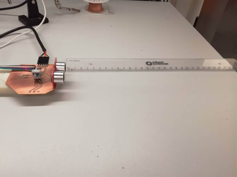
While testing I noticed that the distance oscillated quite heavily, so following Neil's code recommendation I implemented a simple low pass filter:
filt = (1-eps)*filt+eps*counter;//Counter is the value of the Timer registry.
After this implementation it started to behave a little bit more stable as shown in the following video:
In the video I set a testing measure of 10 cm.
Defining the threshold through a knob
In this case, I utilized the knob connected to PA5 to define the threshold. I utilized the ATTiny's ADC to perform the conversion. It transforms the Voltage [0-5] to a 10 bit value [0 - 1023]. Important NOTE: Since the programmer and the potentiometer share pins, it is important to remove the programmer before starting manipulating the potentiometer. Otherwise, odd values will appear.
I will focus in the code to extract the value from the potentiometer and mapped it to a distance. The rest of the code is similar to the one in the previous section. In this case, the threshold variable is not hardcoded but obtained from the knob.
First we need to set up the input port (PA5) as well as the reference value (VCC). See Table 16.3 and 16.4 of the datasheet for more information
    //
   // init A/D
   //
   ADMUX = (0 << REFS1) | (0 << REFS0) | // Vcc ref (Table 16.3)
           (0 << MUX5)  | (0 << MUX4)  | (0 << MUX3)  | (1 << MUX2)  | (0 << MUX1)  | (1 << MUX0);  //Activate PA5/ADC5 (Table 16.4)
The ADC recommended speed is between 50KHz and 200KHz. Since our frequency is 20MHz, we need to reduce the ADC frequency. With a preescaler of 128 our ADC frequency would be 156KHZ that is in the required margin. We are using single conversion mode, that is, we have manually trigger the capture of a value. To that end with need to disable the autotriggering. We should also confirm that we have right adjusted mode (ADCH register contains the higher value while ADCL register contains lower values). Finally, we need to activate the ADC mode. This configuration is setup through the ADCSRA and ADCSRB registers (see section 16.13.2 and 16.13.4 from the datasheet)
  ADCSRA = 0x00;
  ADCSRA = (1 << ADEN) | // enable ADC (16.13.2)
           (0 << ADATE) | // Disable autotriggering. Using single conversion mode.
           (1 << ADPS2) | (1 << ADPS1) | (1 << ADPS0); // prescaler /128
  ADCSRB = 0x00; // (16.13.4)
  ADCSRB = (0 << ADLAR); // Be sure that you have right adjusted mode
When we want to capture a value we need to start the conversion manually. To that end we set the ADCS bit from the ADCSRA register. When the conversion end, hardware will put that bit to 0. When reading the values from the ADCH and ADCL register it is important to start reading the last one.
      // initiate conversion
     //
     ADCSRA |= (1 << ADSC);
     //
     // wait for completion
     //
     while (ADCSRA & (1 << ADSC)) // while there is no 1 in ADCS no continue
        ;
     //Read the distance
     adc_value = ADCL + 256*ADCH; // Read first ADCL and then ADCH
Finally, we need to setup a mapping between the reading value and the associated distance. In this case the measuring range is from 0 to 200 cm [0, 200]. Utilizing the function map (see code) we can can obtain the target distance from the read value
    //Map similar to Arduino map function. From Arduino's WMath.cpp:
    float map(float x, float in_min, float in_max, float out_min, float out_max)
    {
      return (x - in_min) * (out_max - out_min) / (in_max - in_min) + out_min;
    }
    ...
    ...
    ...
    threshold_distance = map(adc_value, 0, 1023, 0, 200); //Map ADC read value [0, 1023] to distance values [0, 200]
Then, as I did in the previous example, I calculate the value of the counter TCNT0 (which is measuring the length of the echo pulse) to reach this threshold, utilizing a macro.
    //FORMULA=> distance (cm) =(pulse_duration(us)/2) / 29.1 (see http://www.instructables.com/id/Simple-Arduino-and-HC-SR04-Example/)
    //          pulse_duration (us) = counter / 20/8 (->frequency: 20Mhz, 20.10^6 ; preescaler=1/8)
    //          SO-> d(cm) = (counter/20/8)/58 = counter*8/1160
    //          and counter = d(cm) * 1160/8

    #define counter_threshold(threshold_cm) (threshold_cm * 1160/8) //Defines the number that should appear in the counter to trigger the LED
    ...
    ...
    ...
    // Calculate the number of counters needed to reach that distance.
    // I use the counter_threshold macro
    threshold = counter_threshold(distance);
    if (counter < threshold){
         set(led_port,led_pin_out);//turn the LED on
      }
      else {
         clear(led_port,led_pin_out); // turn the LED off
      }
Resources utilized
- DIY modules library for HC-SR04 obtained from DIY modules
- Sparkfun electromechanical library for buzzer obtained from Sparkfun Github repository
- Autodesk Eagle 8.1.1 to generate the board and schematics
- Fabmodules to generate the toolpath files (.rml) for the CNC milling machine
- Roland SRM-20 to fabricate the board
- Electronic components, including the ATTiny44, the HC-SR04 ultrasonic sensor module, a potentiometer and a electromagneic buzzer.
- Soldering station, multimeter, power generator
- Rasbperri Pi 3 to program the board. I utilized AVR-GCC Toolchain on Linux for uploading the board to the microcontroller.
Reflection
Summary
During this week I created PCB to demonstrate how a HC-SR04 ultrasonic sensor module works. The idea would be to define a threshold signal using a knob (potentiometer). The range is from 4 cm to 4 m. I have programmed the board using C. I have written my code taking a lot of code from the Fabacademy examples. However, I had to make some fine tuning to them. During the week I could not finished the board but the basic functionality was working.
Main learnings
I practiced a lot with C programming. I finally understood how the Timers, ADC and the Comparators work in the ATTiny microcontroller. I also learnt how to use the HC-SR04 to measure distance and its limitations.
Regarding the board fabrication I learnt that I am creating very narrow tracks from Eagle. In the future I will make wider tracks (at least 0.024).
During this week I also reviewed how to use the oscilloscope to test electronic circuits.
I also learnt how important is to check the connections using also a microscope. I would have noticed earlier the shortcircuit in the Rx pin and would have considerably save my time.
Main difficulties
Surpringlsy the main problem this week came when trying to make the serial port interface. I spent quite a lot of time trying to figure out why it did not work. I measure the signal using an scilloscope and it looked correct, but I could not make the minterm.py communicate with it. Understanding pieces of code was also sometimes challenging.
Circuits and Code
- Eagle Schematics and Board designs.
- avrdude_gpio.conf : configuration file for using Raspberri Pi as a programmer.
- blink.c and blink.make
- test_serial_communication.c and test_serial_communication.c.make
- test_distance_measure.c and test_distance_measure.c.make
- test_distance_measure_serial.c and test_distance_measure_serial.c.make
- test_distance_measure_potentiometer.c and test_distance_measure_potentiometer.c.make