
Week 12. Molding and casting.
During this week I have designed and machined a simple silicone rubber mold to cast small jewelry beads on it.

Tasks
- Design a mold
- Machine a mold
- Build a mold
- Cast an object
Process explanation
Designing the mold
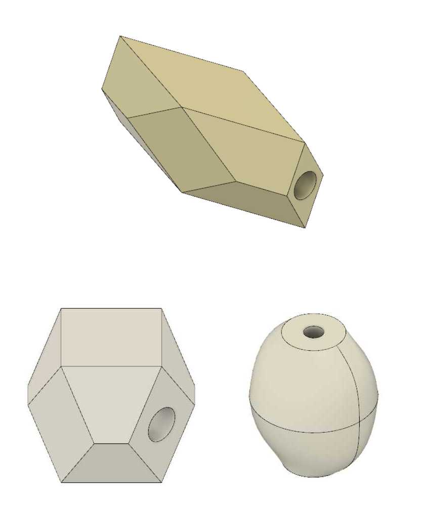
This week we need to machine a the negative of a mold with the CNC milling machine, cast a mold with silicon rubber and after cast a piece on the mold. My plan for this week was to design three different beads shapes so they can be added for instance to a collar or to a bracelet. I made threee designs using Fusion 360 (See Figure1).
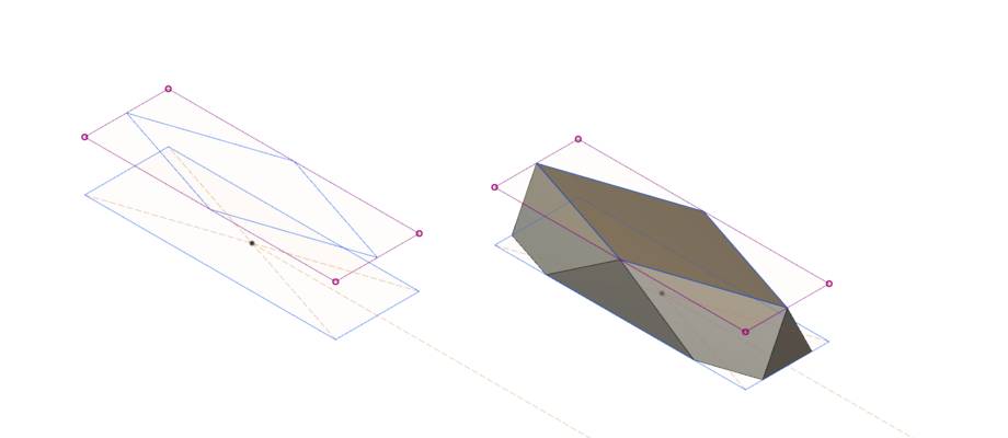
I designed the first bead using parametric design. The design was quite simple. I create two different bodies estruding two different sketches: a rhombus and a rectangle. I then made the intersection of both of them (Figure 2)
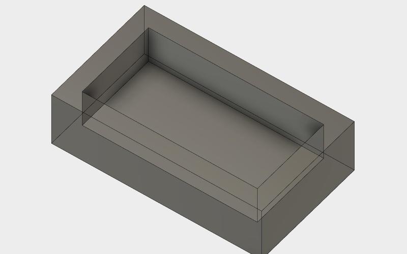
Since this is the negative mold we need to create a box to host the rubber silicon for the mold. I made a box and utilized the shell tool. The thickness of the wall was 4 mm. The milling bit I was going to use was 3.18 mm (1/8 inches), so the distance between the piece and the wall should be minimum that. I finally left 5 mm between the piece and the wall. This turned out to be making the casting more difficult, since the rubber silicone did not flow correctly through the hole. Wider distance would have been better. Next time I would keep bigger distance (at least 8 mm)
I built the walls with a small inclination (1 degree) so it is easier to extract the mold and the silicon flows better inside the mold. I utilized the Draft tool to that end.


Finally, I brought the piece, the box and the cone together in the same design and joined them. Figure 6 shows the final model.

I was planning to have two sides mold. However, since my piece has a symmetry axis I just need to build one negative mold. Out of this I can be the two parts of the rubber mold.
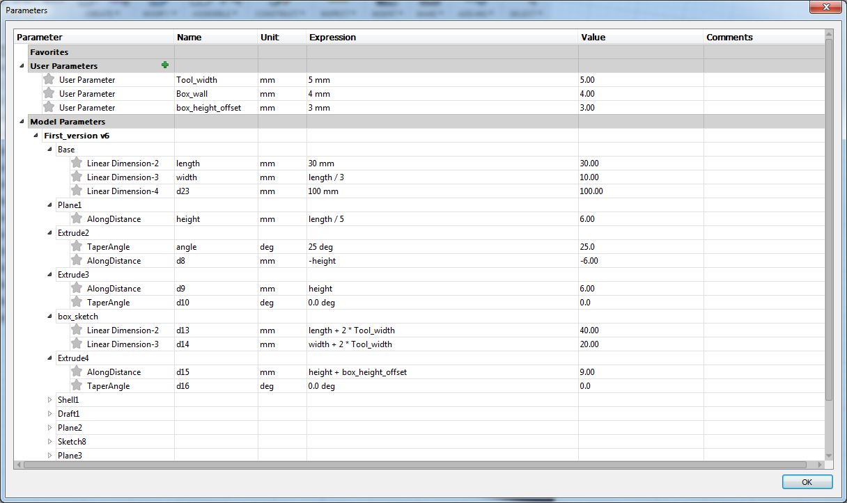
I built the mold using parametric designed. It allows me to create a new piece just by changing some of the dimensions (see Figure 8). In this case width and length had the same measure.

Fabricating the mold
I have used a Roland SRM-20 CNC milling machine for fabricating the negative mold. I utilized a 3.18 mm flat milling bit for the milling (both roughing and finishing). This time I utilized the Modela Player 4 to generate the toolpaths.
When milling a 3D object using a CNC you must follow at least two process: roughing, that is, creating the general structure of the 3D object and finishing a most accurate operation that mill the details and remove the rough surfaces generated in the previous process. This is how I utilized the Modela Player to build the toolpaths:
- Import the STL file from Fusion 360 to Modela Player. This time I decided mill two of the beads at the same time.
- The from the Set > Model menu I had to choose which was going to be my top surface. Actually, it took me some time to understand which was the right position due to the line mess. Since I already have count on the margins in my fusion design, I set margins to 0 in modela.
- Next step if define the settings for roughing. I selected the default settings. I utilized the whole cutting area and I chose the contour lines toolpath for cutting. Finalising process will correct the milling marks.
- Next, I setup the rough cutting parameters. The most importants ones were cutting-in amount (that is, how deep goes the milling bit in each path, or other way, the distance between vertical paths), and the path interval (that is the offset). Since I utilized a 3.18 flat milling bit, I thought that a cutting-in amount of 1mm would work. In addition a 50% path interval would be OK. Since the wax is a soft material, I increased the xy speed from 10 to 30 mm/sec.
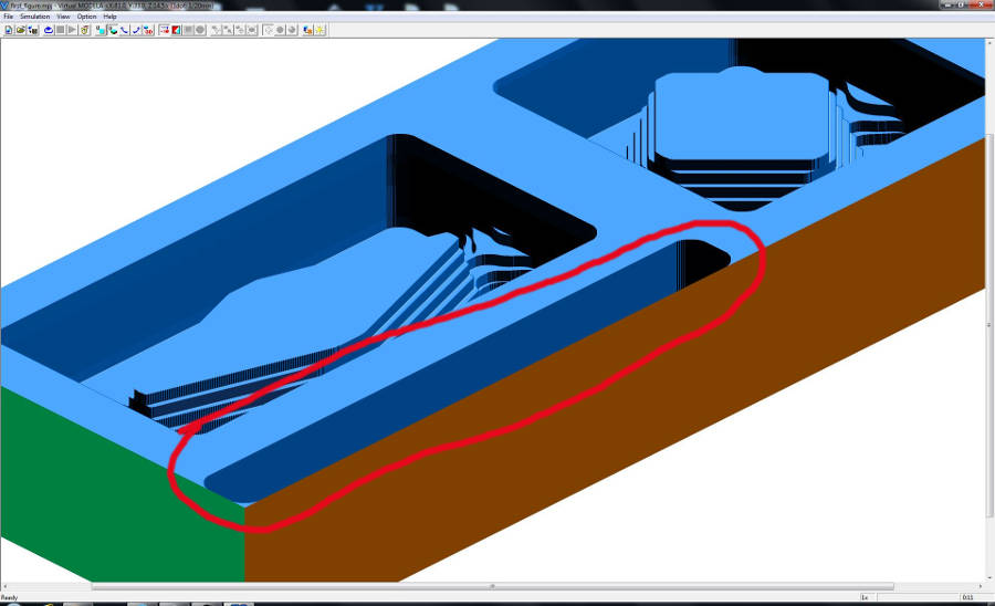
- I utilized Virtual Modela to simulate the toolpath. It is accessible from Modela Player (File > simulate). The simulation showed that since the two models had different lenghts, the toolpath create an unneccessary pocket (See Figure 14). I decided to redesign the 3D model, so both models have the same length and avoid milling the pocket.
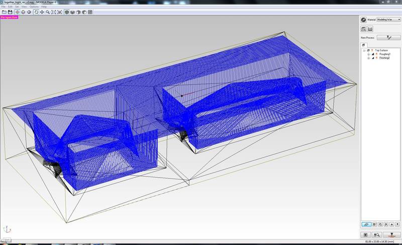
- After that I created a new process, in this case the Finishing project. In this case I utilized scan lines in the X direction. The rest of the settings were the default ones (See Figure 14). However, the simulation with Virtual Modela showed a little bit rough finishing. I could see the marks of the bit on the object. Hence, I decided to modify the settings. First, I chose to scan both in the X and the Y axis. In addition, I reduced slightly the Path Interval to 0.2 mm (Figure 15). After simulating with Virtual Modela I got a much better result than before (See Figure 17). Hence, I decided that they were the right settings. Everything is ready for molding.


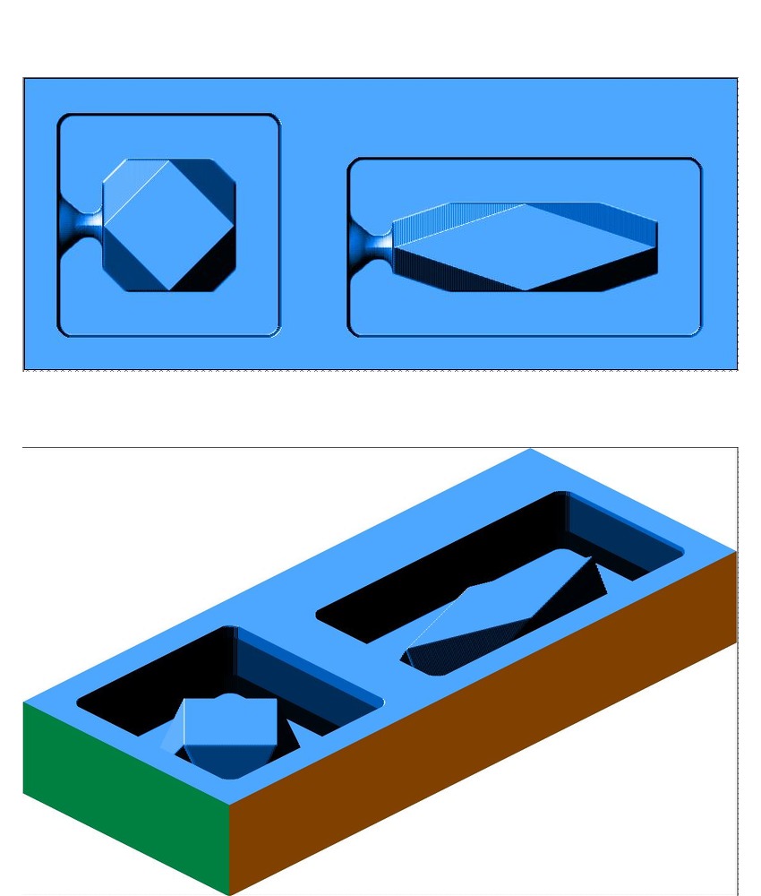
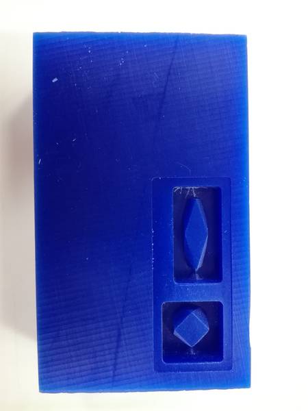
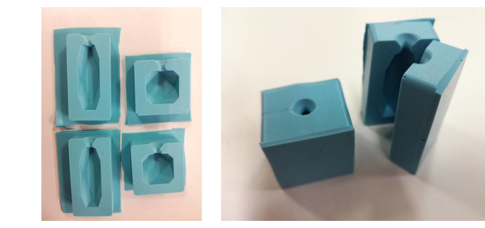
I just select the Mill action from Modela Player to start the milling. The total milling time for roughing was 7 minutes while the time for finishing 39 minutes. I configured the origin to the left bottom corner of the waxing stock and start cutting. Figure 20 shows the resulting mold.


Creating the silicone rubber mold
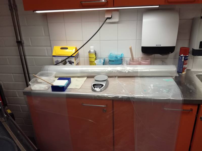
Our Fab manager warned us that all the process was going to be very messy, so we had to put plastic on all the working surfaces.
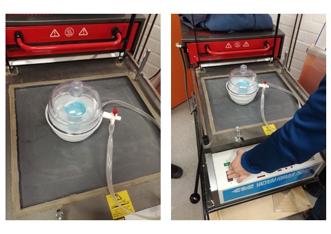
Jani also recommed us to use a vacuum former in order to remove as much as possible the air bubbles, specially with the rubber mold.

Once I got the waxing mold I built the silicone rubber mold. To that end I utilized OOMOO 25 . This is a very easy to use silicon rubber that has a pot time of 15 minutes and a curation time of 75 minutes. Pot time is the time you have before the compound start harden (and hence, you cannot pour it in the mold anymore). Curation time is the time you need to wait before the mold is ready.
During the process you must mix two different liquids (in a proportion 1:1.3 if we use weight or 1:1 if we use volume). You need to mix both liquids around 3 minutes, until the color is homogeneous.

We used a vacuum former for 8 - 9 minutes in order to remove as much air as possible. I started the vacuum for 2 - 3 minutes, stopped and let the air enter again in the vacuum former.
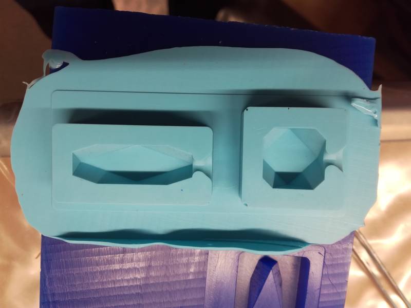
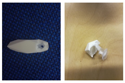
After that I poured the mix in the mold and wait for 75 minutes. It was not successful as you can see in Figure 24. There were bubles of air that ruined the designed. Actually, the problem was that the material was very dense, and could not flow correctly inside the mold. The distance between the wall and the material was only 5 mm, and since the viscosity of the compound was so big it got sticky in the walls could not flow correctly inside the pocket. In the begining I thought that it was a problem on how I did the mix (perhaps I made a mistake with the proportions). Other possibility is that I overpass the pot time. I tried again being sure that the proportions were correct. I repeat the whole previous process and pour the liquid in the mold after 9 minutes. But still I had the same results

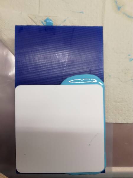
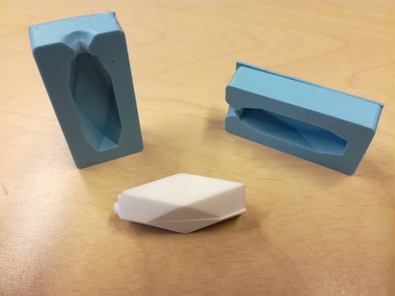
The problem turned out to be that product has been there for more than 1 year and its living time was almost over. Hence, the viscosity of the material was much bigger than it should be. I opened a new packaged and tried again. After opening a new box I finally got my mold ready. This time, learning from the previous failures, and try to create a flat bottom surface for the mold. To that end, I placed a piece of acrylic after placing the mixture in the machining wax mold (Figure 25).
Casting
For casting I utilized Smooth-Cast 310 a casting resin (urethane) of white color with a pot time of 15 - 20 minutes and a curation time of 4 - 5 hours.
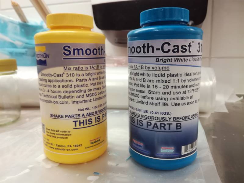
I made the mixture in a disposable container, mixing 1 part of liquid A for each 0.9 parts of liquid B. I stir the mix for approx. 5 min. Since, I have not built any registration feature (my bad), I had to align the borders of the two parts of the mold and stick them around using brown tape. I did not use any release agent, since the resine instructions explained that it was not needed if the mold was done of rubber.
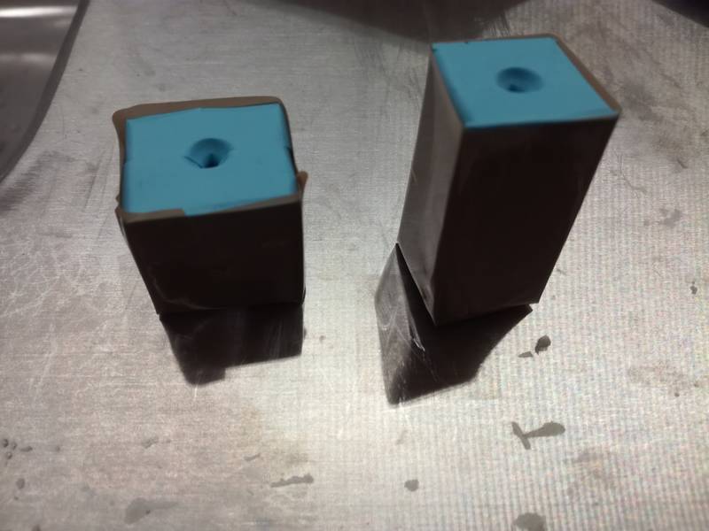
After that, I faced another problem. I forgot to include a tube to allow the air to leave the mold when pouring the casting liquid. Since, the hole was very small, it was really difficult to make the liquid come into the mold. The result: another failure like it is shown in Figure 30. I promise I will never forget to make the hole and the registration when casting. I have learnt this by heart.
I then decided to use a narrow tube that I got after peeling a think cable and a syringe to insert the liquid in the mold. I first inserted the tube through the hole and after that the syringe with the liquid. The syrynge tip did not fit gently into the hole, but I force it a little bit taking advantage from the flexibility of the mold (Figure 31).

I poured the liquid on the mold using the previous method till the it overflow the mold (Figure 32). I had to wait for another 4 hours to check the result.

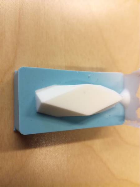
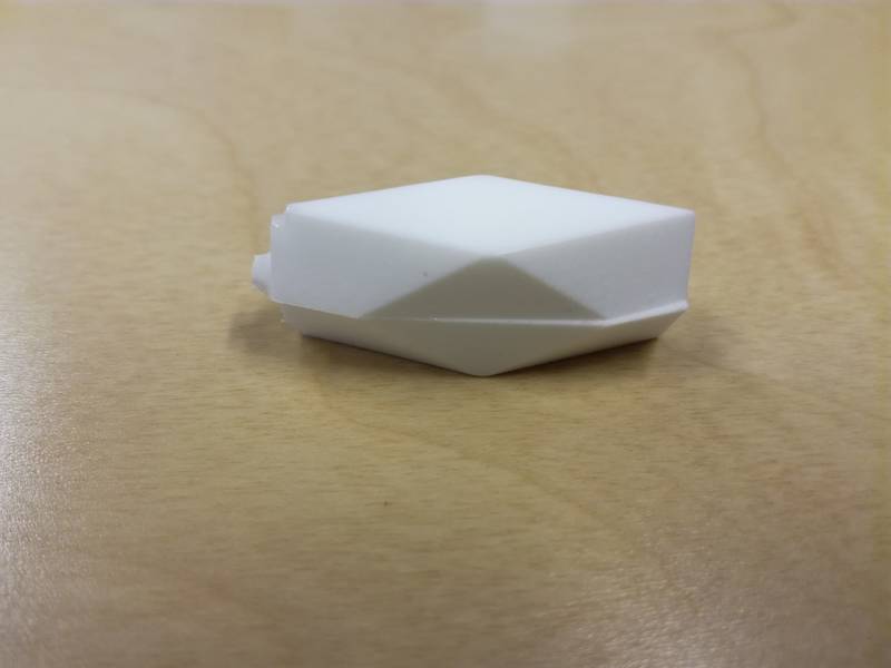
And finally I got it!!. I could unmold the object without any problem, just by squeezing gently the silicon mold.
Reflection
Summary
This week I learnt how to machine the negative of a mold using the CNC milling machine using machining wax as stock. I also learnt how we can create molds out of silicon rubber. This process was totally new for me. been quite I had initially plenty of ideas of what I could do for this week. For instance, I would have liked to have casted something in metal or using the edible mold.
Main learnings
The whole experience has been really educative. I leanrt how to prepare the environment not to mess everything up, the importance of reading safety instructions before starting the process, safety issues (e.g. the necessary equipment you need to use such as gloves, protective glasses ...), how to mix the different components, the importance of reading carefully the instructions to know exactly what you can do and not, how you should mix the different substances, how to use the vacuum former machine to extract air bubble from the mixture, what is exactly the pot time and how you must take care of this time in order not to ruin your mixture, the importance of understanding the limitations of the different materials ...
I realized I missed two different parts when I designed the two sided mold: the registration and a tube to allow the air leaves while pouring the casting material. For the registration, Í would follow Neil suggestion and instead of using tabs or similar I would design the molds in such a way that one mold can be inserted into another..
Main difficulties
I have had my main difficulties while creting the silicone rubber molds. Although, the instructions in the box said that it was ideal for beginners I had to repeat three times the molding. Fortunately, the curing time was just 75 minutes, so I have time to do several attempts during the same time. The main problems were that the silicon rubber was a little bit old, so it was very dense. I had very little space between my piece and the walls so the material did not flow properly and did not cover the whole mold. Another problem came of not using neither registration, nor a tube to let the air flowing out. This caused multiple problems while casting.
Resources utilized
- Fusion 360 to create the 3D models.
- Roland SRM-20 milling machine
- Blue Machining Wax (File-A-Wax)
- Modela player 4 and Virtual Modela software to build the mold toolpaths and simulate the milling.
- Oomoo 25 to create the silicon rubber mold
- Smooth-cast 300 resin to build the pieces
Models
- STL files for the beads' casting molds
- Fusion f3d files for the beads' casting molds