
Week 15. Networking and Communications.
During this week I tried to communicate two boards using I2C protocol
Tasks
- Design a wired/wireless network with at least two microprocessors
- Build a wired/wireless network with at least two microprocessors
Process explanation
General description
During this week I decided to reuse as much as possible the boards that I have done during previously weeks and try to connect them. In the Output Devices assignment I designed a board which contained a LCD display and a DC motor. I could not make it work none of the two designs I implemented due to problems during the design and fabrication. At the same time during the Input devices assignment I built a distance sensor that can execute certain tasks when a threshold is reached (e.g. turning a LED). The threshold can be programmed either mechanically (using a potentiometer) or programmatically.
My intention of this week is:
- Redesign and fabricate a new board for the output devices assignment.
- Connect the boards of output devices assignment and input devices assignment via a bus. My intention is using both I2C and serial synchronous communication (e.g. RS232) and with a computer. I would need to modify slightly the distance senor's board
- If time I would like to add a third bluetooth module which is able to send data received from the sensor to external mobile device.
The initial diagram is shown in Figure 2.
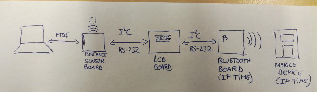
Functional requirements of my network are:
- The sensor board should be able to send measure distance to the LCD boards, which should show the measure distance on the display
- Current threshold value should be sent and visualized in the LCD screen. So, the sensor board should send threshold value to the LCD board via the bus
- The user can modify the threshold via the serial communication with the screen. If user modifies the threshold the new threshold should be sent to both boards
- Additionally, if time, current values read by the sensor board, should be sent to external devices via bluetooth module.
Update 01.06.2017:It turned out that my boards were not working correctly so I had to spend a lot of time redesigning them and building them again. That is why I could not implement the previous functional requirements. I reduced the scope. For instance, The new functional requirements were:
- The sensor board should be able to send measure distance to the LCD boards, which should show the measure distance on the display
- A third board connected to the network should turn one LED on when the distance is further than certain threshold defined in the application. This threshold is defined in compilation time. LED should turn off when the distance is lower thatn the threshold.
Boards design and fabrication
My tasks for this week regarding board design and fabrication are:
- Redo and simplify the board for Output devices assignment. This time I would add just one motor and one LCD display.
- Do some minor hacking to the Sensor's board so I can use it as a bus.
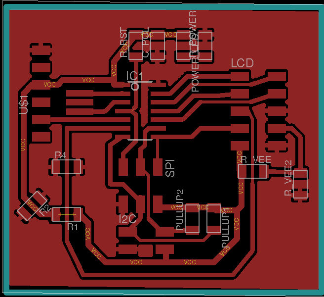
LCD screen design
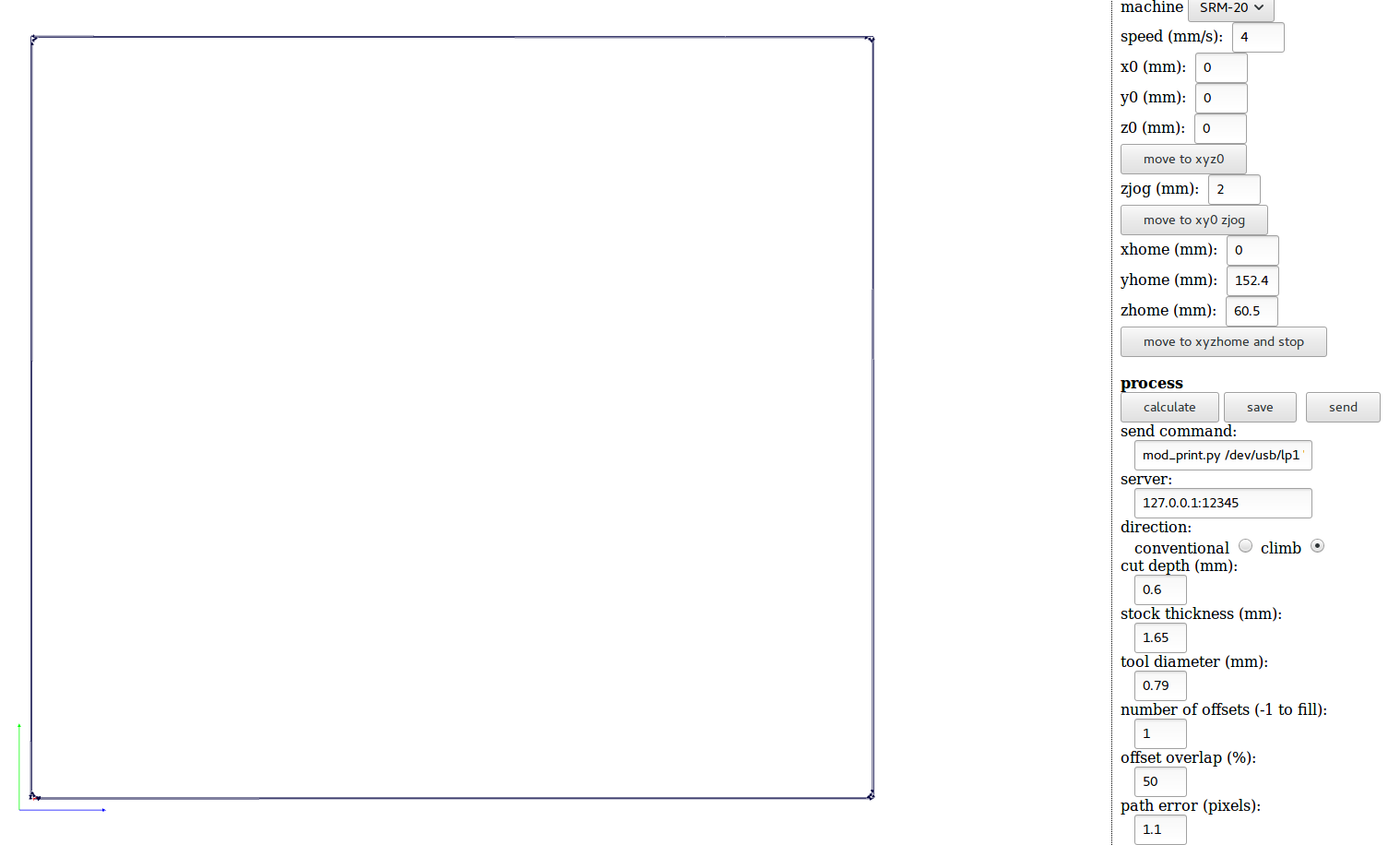
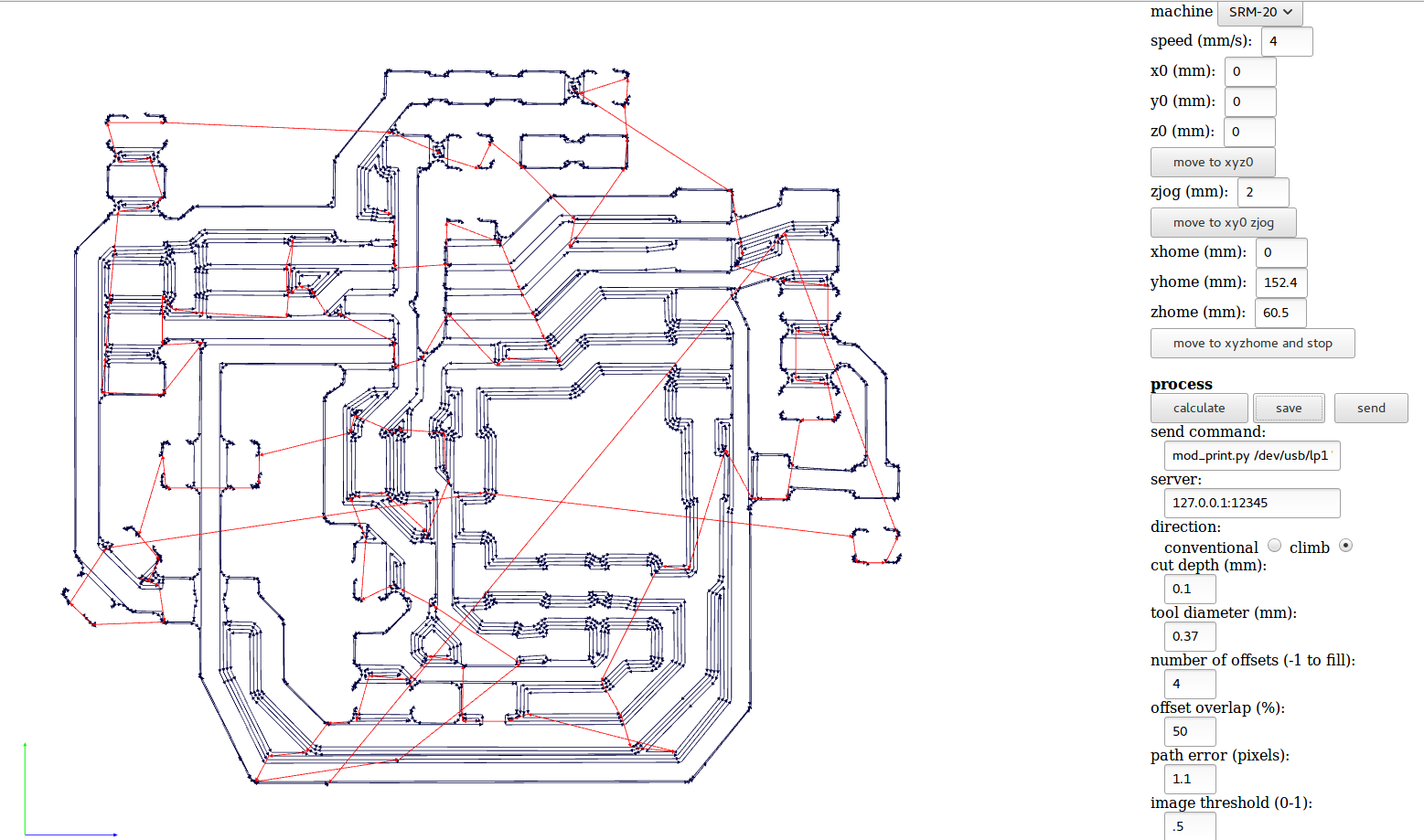
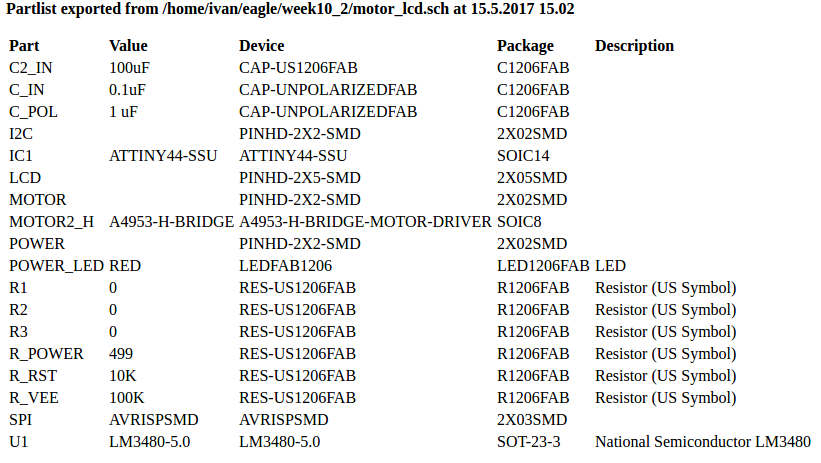
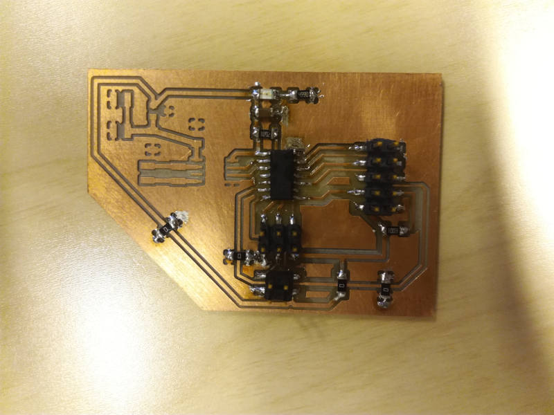
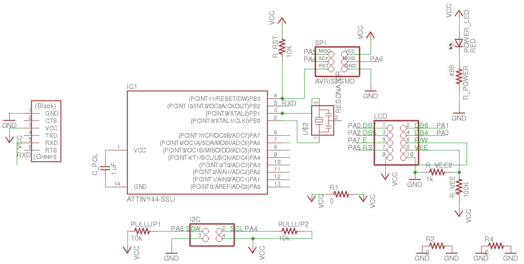
As I mention, this time I redesigned the board of week 10 trying to cover the problems discovered during that week. This time I am using just one motor and the LCD display. In addition, I will add pin headers to connect a communication bus. This bus should be valid for I2C and RS232.
The ATTiny44 supports two different data transfer modes for serial communications through the USI(Universal serial interface port) accordding to datasheet: Two wire mode (TWI) and Three wire mode (SPI). Both of them use synchronous communication (that means that the clock of the master is shared in the bus).
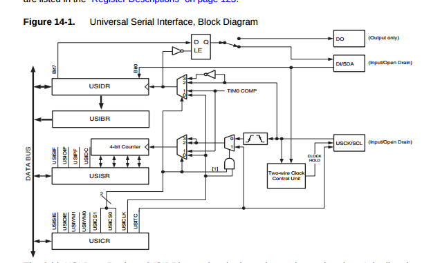
In addition, asynchronous serial communication (no sharing of clock) can be implemented in any output pin of the system, but the communication protocol should be implemented via software (as we have done in previous assignments to establish a connection with the computer via serial port). The datasheets also specify that a Half-duplex UART (Universal asynchronous receiver/transmitter) can be implented using the USI port (see page 123 of the ATTiny 44 datasheet).
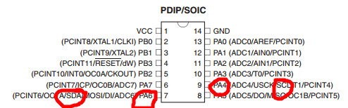
For this assignment initially I decided to use the two wire mode (TWI compatible with I2C). The TWI needs two pins: the SDA pin to transmit the data, and the SCL pin, so the master can transmit the bus clock. If I want to use ATTiny 45 hardware to implement the I2C I need to reserve the PA4 pin for the SCL signal and the PA6 for the SDA signal.
I need to create a pin header to connect the bus. In additoion, since we are using 2x2 mounted headers would be good to include a line in the header for the VCC and the GND signal so we can power the boards using the bus. In any case, it is always necessary that all the boards share the same GND signal. Otherwise, there is no common reference value for voltage.
After knowing this I started redesigning the week 10's board. I removed a motor, change the pinout of the LCD (so the SCL and SDA signals are free and added the header pin to connect the bus.
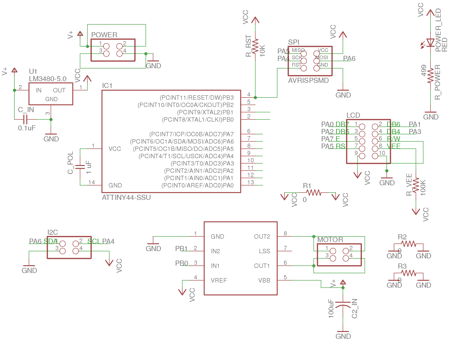
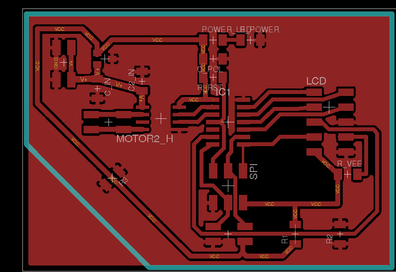
I utilized Eagle software, as in previous weeks, to design the circuits. More information on how to design a circuit using this tool can be obtained in Week 6, week 10 and week 13. This time, and based on previous problems based on narrow lines, I decided to use by default 24 mil for the signal lines unless they should be put in between components. In those cases I used 16 mil lines. For VCC I utilized 32 mil lines. In addition, I utilized pour GND as explained in . Note that I had to use several jumpers (0 Ohm resistors) to connect GND planes in the circuit.. In addition I utilized 0.36 mm as tool diameter in the fabmodules, instead of the 0.36 that I was using in the previous assignments
Problems
I tested the software with a very simple code lcd.c that prints a message in the LCD. However, the LCD did not work at all. I checked several times the connections and they seem correct. There were no shortcircuit and the LCD pins were correctly connected. I checked again the design and I found the following problems:
- The LCD VEE signal is not correctly setup. It should be located in a tension divisor (preferebaly adjustable using a potentiometer). However, I connected directly to a 100K resistor connected to VCC: basically a big PULL up resistor, useless for this approach
- The TWI is more sensible to noise that asynchronous or three wires configurations. Hence, they need to have a pull up resistor (10K) is a good value.
- It was very difficult to debug the code without a serial connection connected to the PC.
Hence, I decided to make a third board. Simplifying it even more.
Second board approach
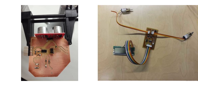
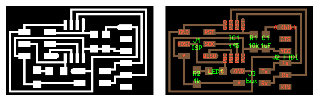
This time, I decided to use a board that might be useful for my final project, and at the same time meet the requirements for the outpud devices assignment. In this case, my board just contains the LCD screen, header for TWI and asynchronous serial communication, and FTDI interface with the PC. In addition, since I have extra pins I added a XTAL to it.
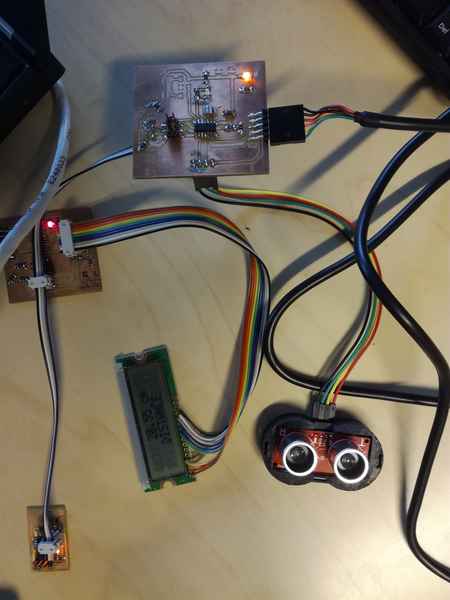
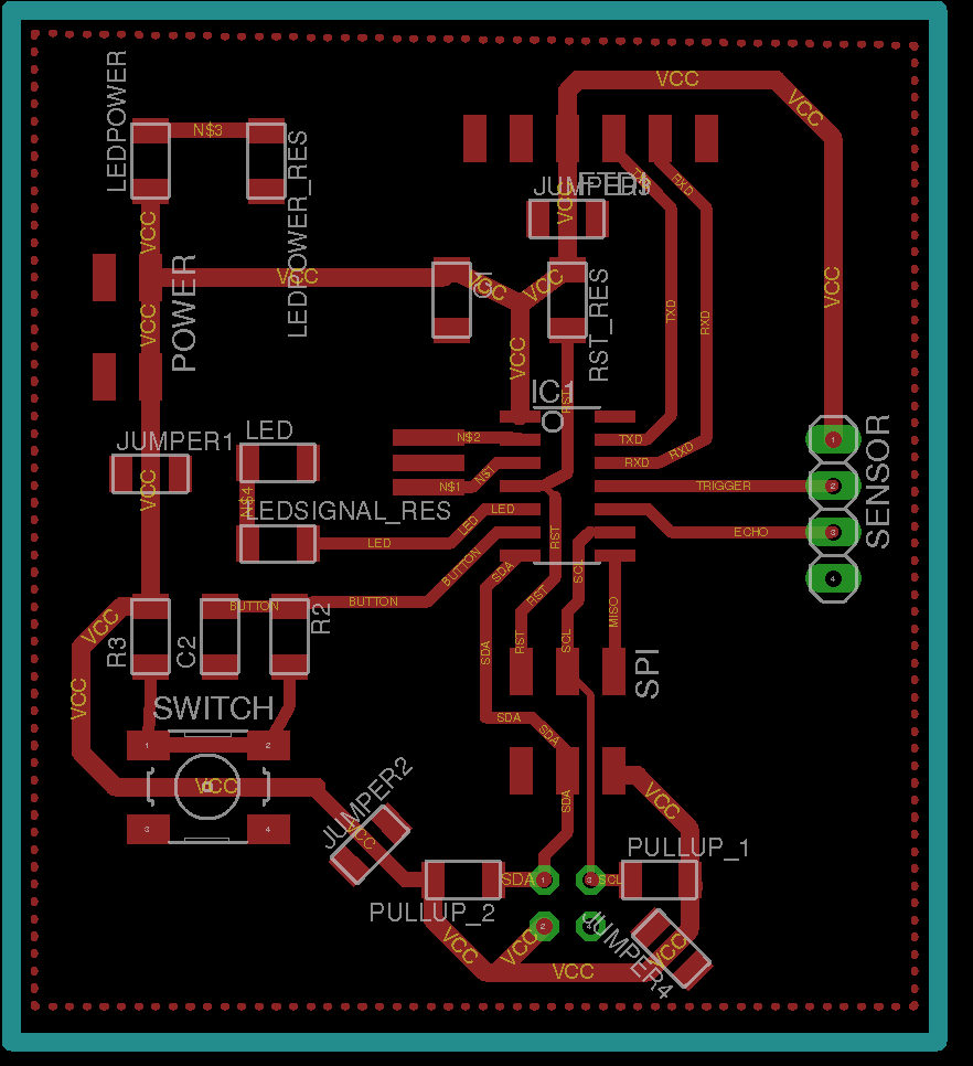
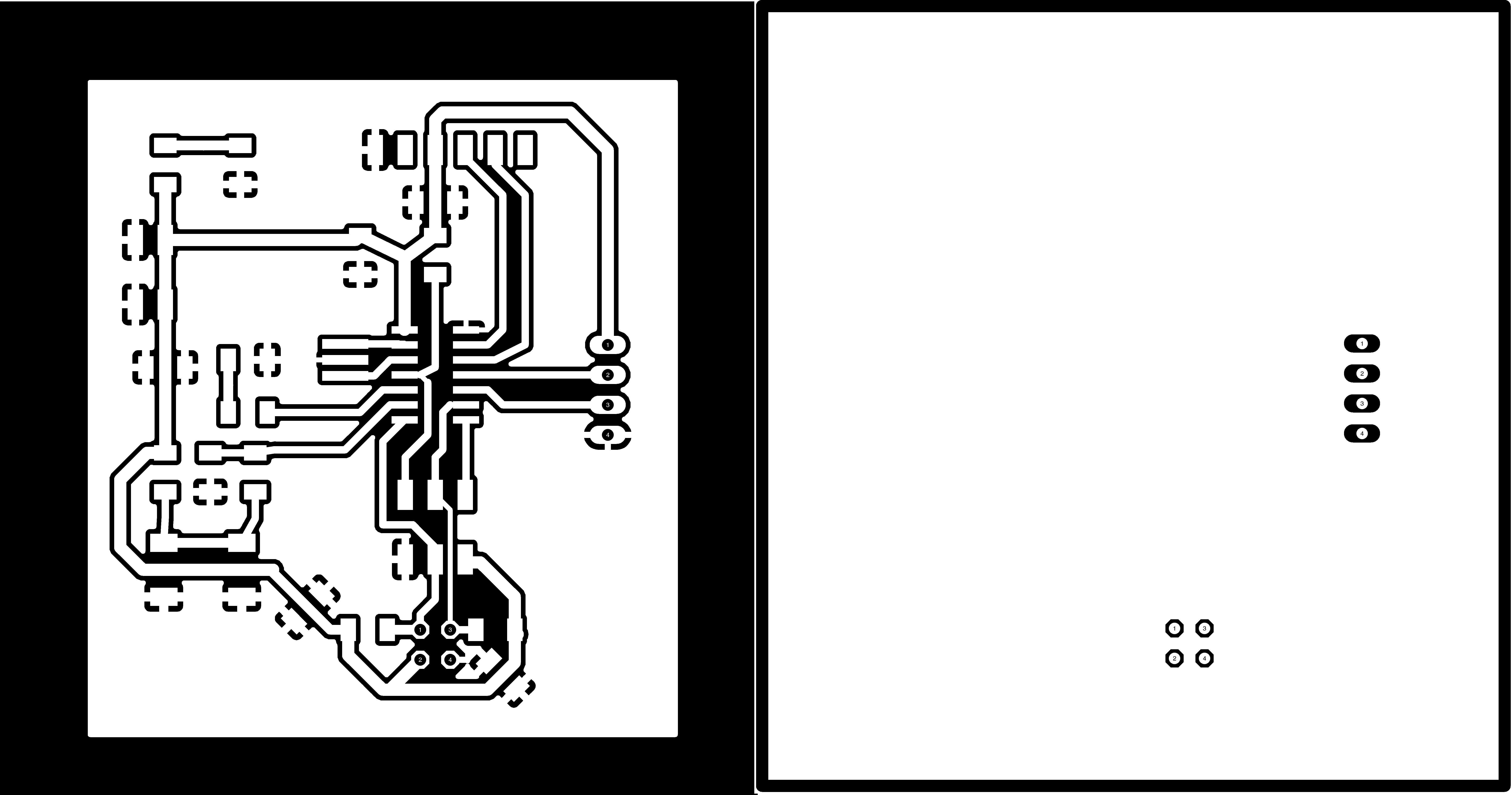
I also modified the distance sensor board from week 13 so it could utilize the I2C protocol. I added the 4 pins header SCL, SDA, VCC and GND. I added the pull up resistor for both signals. I also simplified the board removing uneccessary elements such as the potentiometer. I finally adpated the file to be used in the final project. The board figures are shoown in Figures 15 - 17.
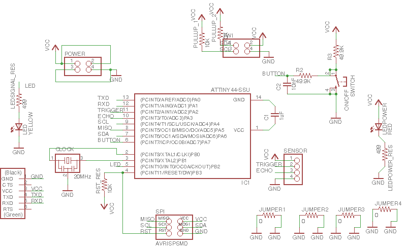
As a threshold LED I decided to reuse Neil's bridge board. This will turn on when a threshold is reached.
Programming
My initial plan was to implement network both using I2C protocol and asynchronous serial communication via software. Since ATTiny44 did not fully support TWI by hardware, I had to implement the protocol by software (following the instructions found here for the master (ATMEL AVR 315), and here for the slave (ATMEL AVR 311) and the page 121 of the ATTiny 44datasheet). In addition at some point I tried to use the libraries provided by ATMEL to use the ATTIny 44 as TWI master (ATMEL AVR315.zip) or TWI slave (ATMEL AVR311.zip). However, I run with some memory problems when I tried to upload the application to the chip (not enough memory). I could not got in detail with this problem due to lack of time. I will try to solve this issue in the future.
Besides my initial ideas, the problems with the boards and lack of time force me to not being able to implement the network using the I2C protocol. I decided just to implement asynchronous serial communication using a very simple software protocol implementation.
I implemented two different software versions:
- First version just communicate the distance sensor with the LCD. The sensor board sends the measured distance as a byte that is processed by the network. Although each device has its own identification, it is basically not utilized.
- In the second version I utilized a more sofisticated protocol. In this case I included a third node (basically a simple board containing a ATTiny 45 with a controllable LED. In this case, each module had a unique id in the network. The distance sensor module acted always as master while the LCD and other node were slaves.

First version: connecting the distance sensor to the LCD to visualize data.
I utilized a two wired serial communication with a baud rate of 9600 bauds/second (that is a bit every 102 microseconds). The distance module was the master, so it was putting distance measured data through the network bus (Tx line) to the LCD (Figure 21)

I utilized the most simple frame (Figure 22). Line is constantly in HIGH value. When the master wants to transmit a byte it puts a LOW (start bit) in the line, then the 8 bits and then the stop bit (a HIGH value).

The code to implement the master is shown next. Note that the put_char includes a complete frame including start and stop bit.
#define output(directions,pin) (directions |= pin) // set port direction for output
#define set(port,pin) (port |= pin) // set port pin
#define clear(port,pin) (port &= (~pin)) // clear port pin
#define bit_test(byte,bit) (byte & (1 << bit)) // test for bit set
#define bit_delay_time 102 // bit delay for 9600 with overhead  ~102 microseconds
#define bit_delay() _delay_us(bit_delay_time) // RS232 bit delay
#define half_bit_delay() _delay_us(bit_delay_time/2) // RS232 half bit delay
#define char_delay() _delay_ms(10) // char delay, before putting another character in the line.
//
// initialize output pins for serial ports
//
set(serial_port, serial_pin_out);
output(serial_direction, serial_pin_out);//Set TX output to HIGH

void put_char(volatile unsigned char *port, unsigned char pin, char txchar) {
   //
   // send character in txchar on port pin
   //    assumes line driver (inverts bits)
   //
   // start bit
   //
   clear(*port,pin);
   bit_delay();
   //
   // unrolled loop to write data bits
   //
   if bit_test(txchar,0)
      set(*port,pin);
   else
      clear(*port,pin);
   bit_delay();
   if bit_test(txchar,1)
      set(*port,pin);
   else
      clear(*port,pin);
   bit_delay();
   if bit_test(txchar,2)
      set(*port,pin);
   else
      clear(*port,pin);
   bit_delay();
   if bit_test(txchar,3)
      set(*port,pin);
   else
      clear(*port,pin);
   bit_delay();
   if bit_test(txchar,4)
      set(*port,pin);
   else
      clear(*port,pin);
   bit_delay();
   if bit_test(txchar,5)
      set(*port,pin);
   else
      clear(*port,pin);
   bit_delay();
   if bit_test(txchar,6)
      set(*port,pin);
   else
      clear(*port,pin);
   bit_delay();
   if bit_test(txchar,7)
      set(*port,pin);
   else
      clear(*port,pin);
   bit_delay();
   //
   // stop bit
   //
   set(*port,pin);
   bit_delay();
   //
   // char delay
   //
   bit_delay();
   }
In this version, each distance can just take values from 0 to 255 (char or uint8_t type. So, when the distance module want to send the distance it just do:
uint_8t distance;
//Calculate distance
//....
//...
put_char(&serial_port, serial_pin_out, distance);
For more information on how the distance data is calculate see the Input devices week.
The LCD screen (the slave in the network) reads the bytes sent by the master. The values are shown on the screen. Note that the bits are read in the middle of the bit. This avoids timing problems between transitions.
#define input(directions,pin) (directions &= (~pin)) // set port direction for input
#define pin_test(pins,pin) (pins & pin) // test for port pin
#define bit_delay_time 102 // bit delay for 9600 with overhead  ~102 microseconds
#define bit_delay() _delay_us(bit_delay_time) // RS232 bit delay
#define half_bit_delay() _delay_us(bit_delay_time/2) // RS232 half bit delay
#define char_delay() _delay_ms(10) // char delay, before putting another character in the line.
input(serial_direction, serial_pin_in);

void get_char(volatile unsigned char *pins, unsigned char pin,  char *rxbyte) {
   //
   // read character into rxbyte on pins pin
   //    assumes line driver (inverts bits)
   //
   *rxbyte = 0;
   while (pin_test(*pins,pin)); // wait for start bit =>0
   //
   // delay to middle of first data bit
   //
   half_bit_delay();
   bit_delay();
   //
   // unrolled loop to read data bits
   //
   // main loop
   if pin_test(*pins,pin)
      *rxbyte |= (1 << 0);
   else
      *rxbyte |= (0 << 0);
   bit_delay();
   if pin_test(*pins,pin)
      *rxbyte |= (1 << 1);
   else
      *rxbyte |= (0 << 1);
   bit_delay();
   if pin_test(*pins,pin)
      *rxbyte |= (1 << 2);
   else
      *rxbyte |= (0 << 2);
   bit_delay();
   if pin_test(*pins,pin)
      *rxbyte |= (1 << 3);
   else
      *rxbyte |= (0 << 3);
   bit_delay();
   if pin_test(*pins,pin)
      *rxbyte |= (1 << 4);
   else
      *rxbyte |= (0 << 4);
   bit_delay();
   if pin_test(*pins,pin)
      *rxbyte |= (1 << 5);
   else
      *rxbyte |= (0 << 5);
   bit_delay();
   if pin_test(*pins,pin)
      *rxbyte |= (1 << 6);
   else
      *rxbyte |= (0 << 6);
   bit_delay();
   if pin_test(*pins,pin)
      *rxbyte |= (1 << 7);
   else
      *rxbyte |= (0 << 7);
   //
   // wait for stop bit
   //
   bit_delay();
   half_bit_delay();
   }
The main routine of the LCD will read constantly the line, store the value in a char variable, and write the value on the LCD screen. The write measure method just use the same algorithm as explained in Output devices week.
unsigned char chr;
while (1) {
    get_char(&serial_pins, serial_pin_in, &chr);
    write_measure(chr, -1);
 }
Second version: three nodes in the network
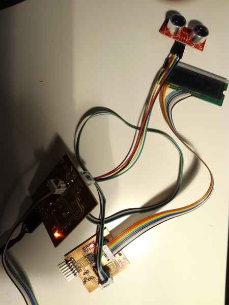
In this case I added a new node to the network. Basically, it is just a board containing a ATTiny 44 and a LED. The distance sensor will make this LED turned on when certain threshold is reached. The general schema is shown in Figure 23.

In this case, there are different nodes, so each node should be identified by an address. Furthermore, there are several commands, and some of them require extra payload, and some of them none. Since we are using asynchronous serial connection we need to define a frame with a preamble (helps to synchronize the slave), the target address, the command and the command payload. The protocol is summarized in Figure 24.
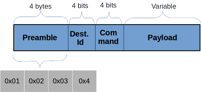
- Preamble: It consists of 4 bytes, which value are
0x01, 0x02, 0x03, 0x04 - Destination address: It consists of 4 bits (half byte). The address space would be then 16 devices. However, in order to avoid that any of the preamble bytes coincide with any possible address, the initial bit is always 1, reducing the address space to 8 devices. Enough for this project.
- Command: It consists of 4 bits. Possible values:
- 0x00: WRITE_VALUE: Writes a distance value in the LCD screen. Its payload has a fixed size of 4 bytes. Actually, the payload is a float serialized through the network.
- 0x01: WRITE_UNIT: Modifies the unit. The distance module must send a string containing the new unit. The payload has a fixed lenght of 3 bytes.
- 0x02: WRITE_TEXT: Writes any text in the lower line of the LCD screen. The payload has a variable lenght. The first byte of the payload indicates such length
- 0x03: LED_ON: Turn a board LED on.
- 0x04: LED_OFF: Turn a board LED off.
- Payload: Depending on the command the size might be fixed or variable. If the payload has a varaible size, the first byte of the payload indicates such lenght.
The routines to read and write data on the network are the same as the ones define in the first version. However, in this case, the master must compose the frame and the slave shoulde be able to process it. I will provide three different examples: Code implementing the WRITE_VALUE (fixed payload length), WRITE_TEXT(variable payload length) and LED_ON(no payload).
Let's start with the code to send a distance value. In this case the distance value is a float that must be serialized. To that end I use a union, in which I can get either the full float or the byte array of 4 elements which serialize the float:
static  const uint8_t WRITE_VALUE = 0;
static  const uint8_t WRITE_UNIT = 1;
static  const uint8_t WRITE_TEXT = 2;
static  const uint8_t LEDON =3;
static  const uint8_t LEDOFF = 4;

#define node_id 15
#define distance_id 14
#define screen_id 8
#define serial_id 9
//Union utilized to serialized the software.
typedef union
{
    float f;
    uint8_t bytes[4];
    } uFloatData;
void send_distance(float distance) {
   output(serial_direction, serial_pin_out);//Be sure that we have a 1 in the line.
   // Write Preamble
   put_char(&serial_port, serial_pin_out, 1);
   put_char(&serial_port, serial_pin_out, 2);
   put_char(&serial_port, serial_pin_out, 3);
   put_char(&serial_port, serial_pin_out, 4);
   //Send id and command in the same byte. The id will occuppy the first 4 bits while the command the next bytes. Send command is 0x00
   uint8_t command = screen_id << 4 | WRITE_VALUE;
   put_char(&serial_port, serial_pin_out, command);
   //Send measure
   //Is going to have a float
   uFloatData output;
   output.f = distance;
   uint8_t i=3; //Fixed lenght of payload: 4 bytes.
   //Write the distance serialized as a float.
   do {
    put_char(&serial_port, serial_pin_out, output.bytes[i]);
    i--;
   } while(i);
     //HIGH-Z
     input(serial_direction, serial_pin_out);
}
A similar code for turning the LED on. In this case there is no payload.
static  const uint8_t WRITE_VALUE = 0;
static  const uint8_t WRITE_UNIT = 1;
static  const uint8_t WRITE_TEXT = 2;
static  const uint8_t LEDON =3;
static  const uint8_t LEDOFF = 4;

#define node_id 15
#define distance_id 14
#define screen_id 8
#define serial_id 9
void send_led_command( ) {

   output(serial_direction, serial_pin_out);
   //Preamble
   put_char(&serial_port, serial_pin_out, 1);
   put_char(&serial_port, serial_pin_out, 2);
   put_char(&serial_port, serial_pin_out, 3);
   put_char(&serial_port, serial_pin_out, 4);
   //Send command
   uint8_t command = node_id << 4 | LEDON;
   put_char(&serial_port, serial_pin_out, command);
}
And finally and example when there is variable size payload.
static  const uint8_t WRITE_VALUE = 0;
static  const uint8_t WRITE_UNIT = 1;
static  const uint8_t WRITE_TEXT = 2;
static  const uint8_t LEDON =3;
static  const uint8_t LEDOFF = 4;

#define node_id 15
#define distance_id 14
#define screen_id 8
#define serial_id 9

void send_text(char text[]) {
   output(serial_direction, serial_pin_out);
     //Preamble
     put_char(&serial_port, serial_pin_out, 1);
     put_char(&serial_port, serial_pin_out, 2);
     put_char(&serial_port, serial_pin_out, 3);
     put_char(&serial_port, serial_pin_out, 4);
     //Send command
     uint8_t command = screen_id << 4 | 0x02;
     uint8_t size = (uint8_t)strlen(text); //Calculate the size of the text string
     put_char(&serial_port, serial_pin_out, size); //Send the size
     put_string(&serial_port, serial_pin_out, text); Send all the charachers
     input(serial_direction, serial_pin_out);
}
The receiver should be able to process each frame. First should be able to process the preamble. Then find the target id. If the frame is not targeted to this node then it should discard the rest of the process and start waiting again for the preamble. In this case, I am providing two examples: one for the LCD screen and one for the LED node.
static  const uint8_t WRITE_VALUE = 0;
static  const uint8_t WRITE_UNIT = 1;
static  const uint8_t WRITE_TEXT = 2;
static  const uint8_t LEDON =3;
static  const uint8_t LEDOFF = 4;

#define node_id 15
#define distance_id 14
#define screen_id 8
#define serial_id 9
typedef union
{
    float f;
    uint8_t bytes[4];
    } uFloatData;
int process_frame(){
    uint8_t byte1=0, byte2=0, byte3=0, byte4=0, command =0;
    //Search the start of the frame
    while (1) {
      byte1 = byte2;
      byte2 = byte3;
      byte3 = byte4;
      byte4 = command;
      get_char(&serial_pins, serial_pin_in, &command);
          if ((byte1 == 1) & (byte2 == 2) & (byte3 == 3) & (byte4 == 4)){
            //Preamble found
            //Reset the preamble.
            byte1=byte2=byte3=byte4=0;
            //Process the rest of the bits.
            break;

          }
    }
    // Analyze the id if itis not the one just remo
    uint8_t id = command >> 4;
      if (id != screen_id) {
        //If it is not targeted to this node do not process more and find again the preamble.
        return;
      }

    //If this is the right node extract the command
    command = command & 0x0F;

   //If command is WRITE_VALUE
   if (command == WRITE_VALUE){
   //Is going to have a float
     uFloatData input;
     uint8_t i=3;
     do {
      get_char(&serial_pins, serial_pin_in, &input.bytes[i]);
      i--;
     } while(i);
     //Once the float is deserialized write it on the screen.
     write_measure(input.f);

   }

   //If command is WRITE_TEXT
   else if (command == WRITE_TEXT){
        uint8_t length;
        //Get the char length
        get_char(&serial_pins, serial_pin_in, &length);
        //Read the characters of the payload and write them on the LCD screen
        while (length){
          uint8_t chr;
          get_char(&serial_pins, serial_pin_in, &chr);
          write_character(chr); //Write character on the LCD screen.
          length --;
        }
    }
}
And finally the code for turning on/off the LED:
static  const uint8_t WRITE_VALUE = 0;
static  const uint8_t WRITE_UNIT = 1;
static  const uint8_t WRITE_TEXT = 2;
static  const uint8_t LEDON =3;
static  const uint8_t LEDOFF = 4;

#define node_id 15
#define distance_id 14
#define screen_id 8
#define serial_id 9
int process_frame(){
    uint8_t byte1=0, byte2=0, byte3=0, byte4=0, command =0;
    //Search the start of the frame
    while (1) {
    byte1 = byte2;
    byte2 = byte3;
    byte3 = byte4;
    byte4 = command;
    uint8_t byte1=0, byte2=0, byte3=0, byte4=0, command =0;
    //Search the start of the frame
    while (1) {
      byte1 = byte2;
      byte2 = byte3;
      byte3 = byte4;
      byte4 = command;
      get_char(&serial_pins, serial_pin_in, &command);
          if ((byte1 == 1) & (byte2 == 2) & (byte3 == 3) & (byte4 == 4)){
            //Preamble found
            //Reset the preamble.
            byte1=byte2=byte3=byte4=0;
            //Process the rest of the bits.
            break;

          }
    }
    // Analyze the id if itis not the one just remo
    uint8_t id = command >> 4;
      if (id != noden_id) {
        //If it is not targeted to this node do not process more and find again the preamble.
        return;
      }
    //If it is the right address check the command.
    command = command & 0x0F;

   //If command is LEDON
   if (command == LEDON){
       clear(led_port, led_pin); //LED has pull up resistor.
   }

   //If command is LEDOFF
   else if (command == LEDOFF) {
       set(led_port, led_pin);
   }
}
Future development
I have been considering how to easily be able to connect multiple masters at the same time for future development. The possible implementation would be the following:
- When one master device is not transmitting it should put the output in high impedance (tri-state)
- Before start transmitting the master should check that there is no other master transmitting, that is, that the line is in High Z. I got some ideas from this forum page.
- Disconnect internal ATTiny pull-up resistor.
- Connect pin via pull down resistor (~100K).
- Read a pin state
- Wait a short delay (~ 10 us)
- Switch On interal Pull-Up
- Read a pin state
- If internal Pull-Up will change pin state => pin is floating; if both samples are 0 then the line is in LOW; if both samples are then the line is in HIGH value.
In addition, I am planning to check how to implement the I2C protocol.
Resources utilized
- SRM-20 CNC router to build the circuits
- Ultrasonic sensor module
- LCD module
- Electronic components from the fabinventory
- Digital oscilloscope to measure signals.
Models And code
Majority of the files from the distance module are heavily based on Neil's distance code. Majority of the networking protocols are based on Neil's hello.bus.c file for asynchronous serial communication.
- lcd.c and lcd.make to test the LCD
- distance.c and distance.make to test the distance module
- network_distance.c and network_distance.c.make. Implements the first version of the network protocol and receives data from the ultrasonic sensor module.
- network_lcd.c and network_lcd.make. Implements the first version of the network prototocol and presents data in the lcd.
- network_distancev2.c and network_distancev2.c.make. Implements the second version of the network protocol and receives data from the ultrasonic sensor module.
- network_lcdv2.c and network_lcdv2.c.make. Implements the second version of the network prototocol and presents data in the lcd.
- network_nodev2.c and network_nodev2.c.make. Implements the second version of the network prototocol and presents data in the lcd.
- distance board's schematics and board's file
- lcd board's schematics and board's file