
Week 10. Output devices.
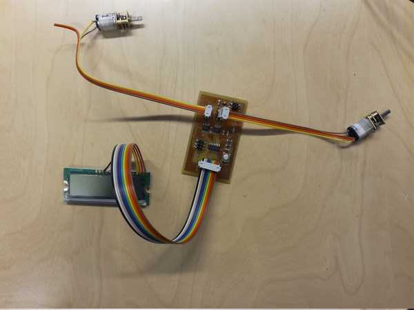
During this week i have fabricated a simple board which is able to drive two motors and visualize status information on a LCD display.
Tasks
- Add an output device to a microcontroller board
Process explanation
Understanding PWM
Prototype design
My idea of this week was to start working on the final project. I wanted to make a initial prototype on how to implement the movement and the basic output feedback through a LCD screen. My intention is to build a small robot with two wheels that executes 10 random movements (among go forward, turn left, turn right, go backward) in a row. The list of movements are generated randomly after powering the microcontroller. The set of movements are shown in the LCD screen using arrows. Current movement is emphasized.

Before deciding which microprocessor should I use I first need to know how many GPIO I am going to use. I am going to use two motors, and the H-Bridge associated to each motor would use 2 output pins so I would need 4 GPIOs for the control of the motors. I would need one pin for the button and another for the reset button. The LCD would require a minimum of 6 pins: 4 for data, 1 for RS (decide if sending data or commands) and for E pin (Enable pin). In addition I would need two pins for the external clock. Total is 14 pins. However the ATTiny 44 just have 12 GPIO. So I had three options:
- Remove the external clock and work with the microprocessor speed (8MHz)
- Use two ATTiny44 and connect them using the USI to connect both of them
- Use another microprocessor with more GPIOs
Since I do not have any time critic task, and I do not need any serial communication I decided that the most efficient option (in terms of effort and time) is to remove the external clock. I hope it has been a good decision.
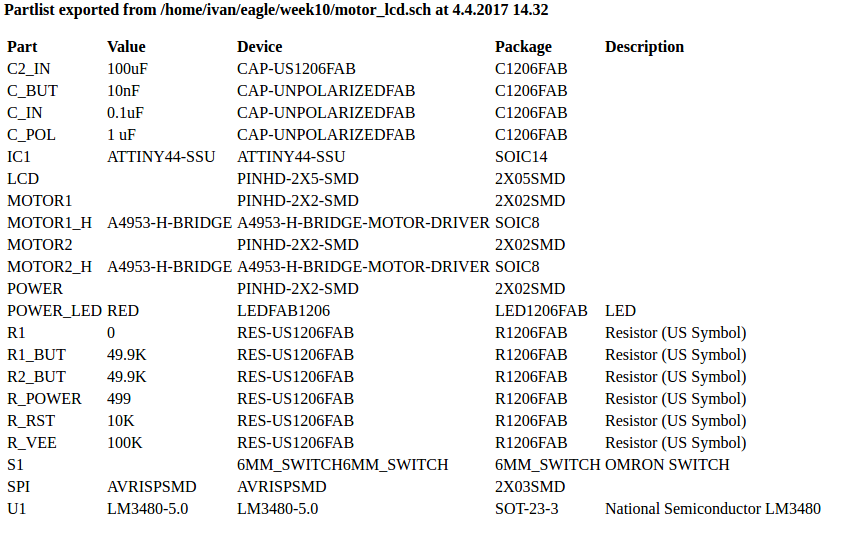
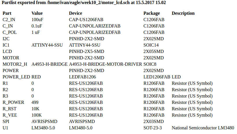
Bill of materials
- Voltage regulator: LM3480IM3-5.0/NOPBCT-ND
- 2 Brushed DC motors
- H-Bridge A4953
- LCM-S01602DTR/M LCD screen containing a HD44780U controller
- Switch TACT SMD W-GND 160GF
- Red power LED
- Batteries
- Microcontroller
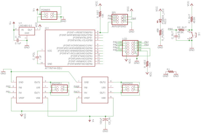
Next I created the schematics. To that end, I had to read the specification sheets for the LCD regulator and H-Bridge
LCD
It was difficult to understand the pinout of the 16x2 characters LCD just using its datasheet. A lecture to this tutorial threw some lights and reading the integrated controller datasheet (44780U) allowed me to understand how the LCD would work. The LCD driver offers the possibilite of using a 8 bit or 4 bits command mode. In order to save pins in the controller I chose the 4 pins mode. I just need to add a pin header of 2x5 in the board in order to connect the cable.
Voltage regulator
I chose the LM380 5V regulator. It ensures 2A of current in the output. More than enough for feeding the microcontroller and the LCD display. It demands two capacitors of 1uF one in the input (Between V+ and GND) and one in the output (between VCC and GND) When I was trying to add it in my schematics I could not find it in the Fab Academy library so I downloaded it from the following site
H-Bridge
I used one A4953. It is quite simple to use. It receives two inputs from the microcontroller. Each input must be either a PWM signal or GND. It has two outputs to connect the motor. Depending on the combination of Input/Output it makes the motor to move forward (INPUT1=1 and INPUT2=0), backwards (INPUT1=0 and INPUT2=1) or brake (INPUT1=1 and INPUT2=1). In order to use PWM current control, a low-value resistor is placed between the LSS pin and ground for current sensing purposes. However I did not use this option. In addition this component requires two capacitors of 0.22 and 100uF between V+ and GND
Working with Eagle
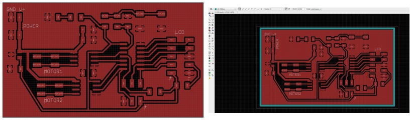
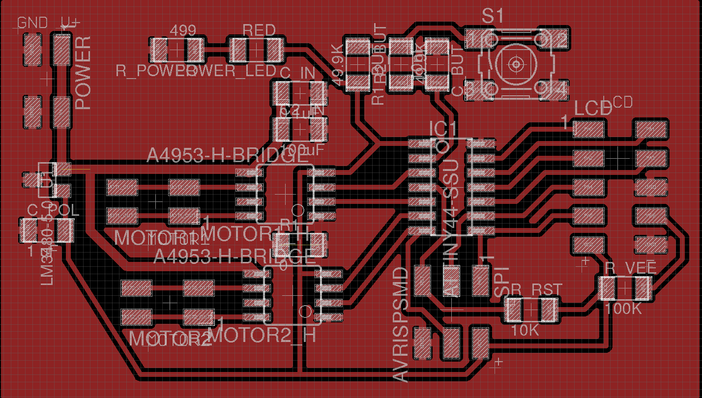
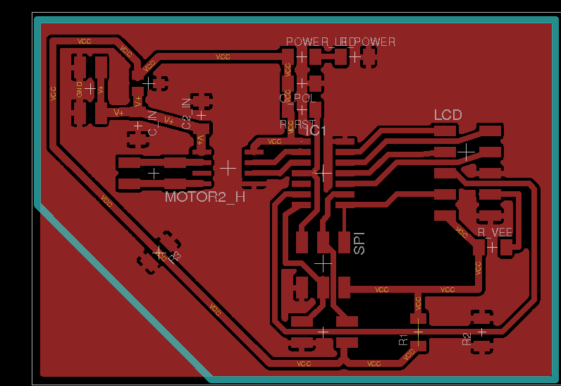
Following the same steps as in week 6, I created the PCB using Eagle based on the sketch of Figure 1. The schematics of the PCB are shown in Figure 3
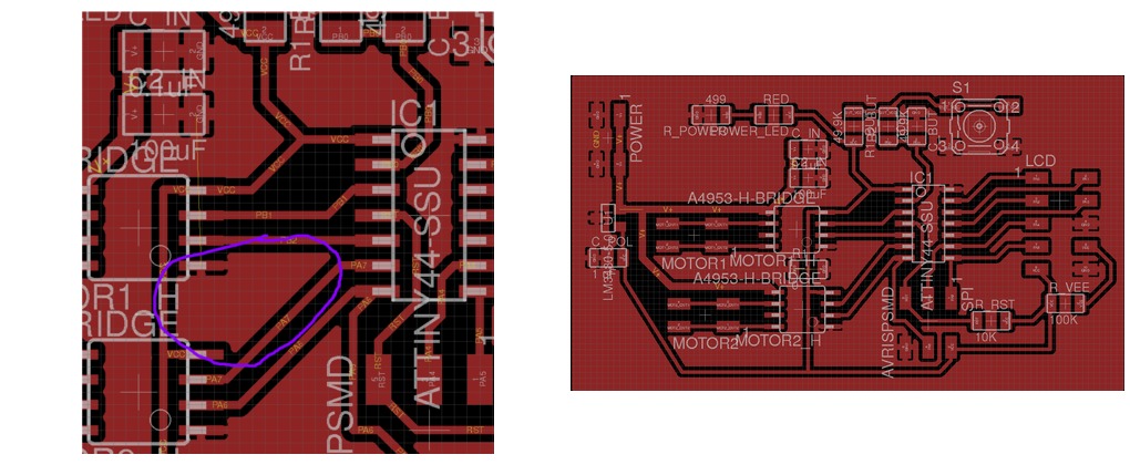
I place and route the components manually in the Eagle's board view. I utilized a width of 0.016 inches for all the tracks, except for the ones which connect V+ to the H-Bridge for which I used double width (0.032 inches). I used a grid of 0.025 inches and Alt resolution of 0.005 inches. Since, this time I had many components and I did not want to make vias, I decided to make a copper pour, that is, use the whole board plate as a GND signal. This save space in the PCB (no need for a GND track) as well as speed up the milling time since we do not have to clean the board from copper but do only isolation milling. To do that, once all the signals (except GND) are route, you create a polygon around the PCB. After that, open the properties of the polygon using the button with an information signal. There, it is important to modify the Isolate parameter. I chose 16mil since this is the size of the milling bit. After that, and using the Name button, the signal should be renamed to GND. Finally, pressing the Ratsnest button it creates the ground plane.
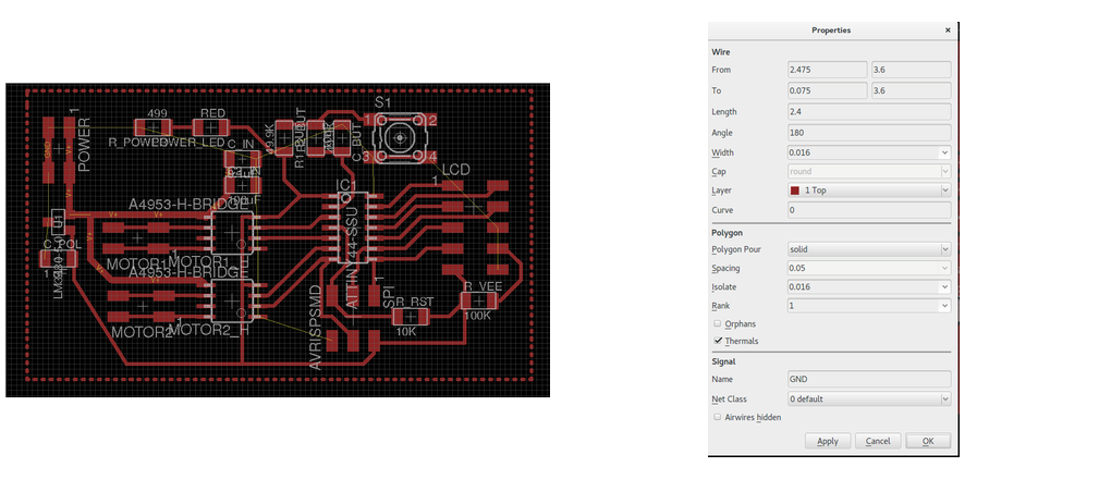

I realized that there was one area of the board that was isolated so it did not have the same GND plane (See Figure 6). So, I had to put a 0 ohm resistor in between to connect the areas
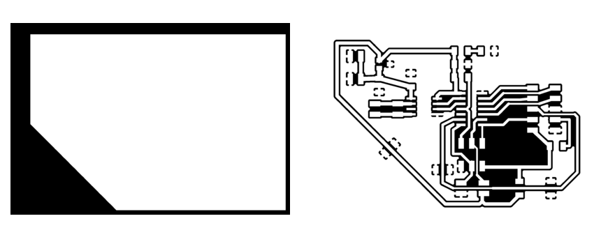
After that I added some text in the TPlane, mainly to identify polarity of input signals, and I created a polygon for cutting the board in layer 46:Milling.
I run successfully the Design Rule Check with the following settings:

The final board is shown in the follwing figures.


Fabrication and coding
Fabrication
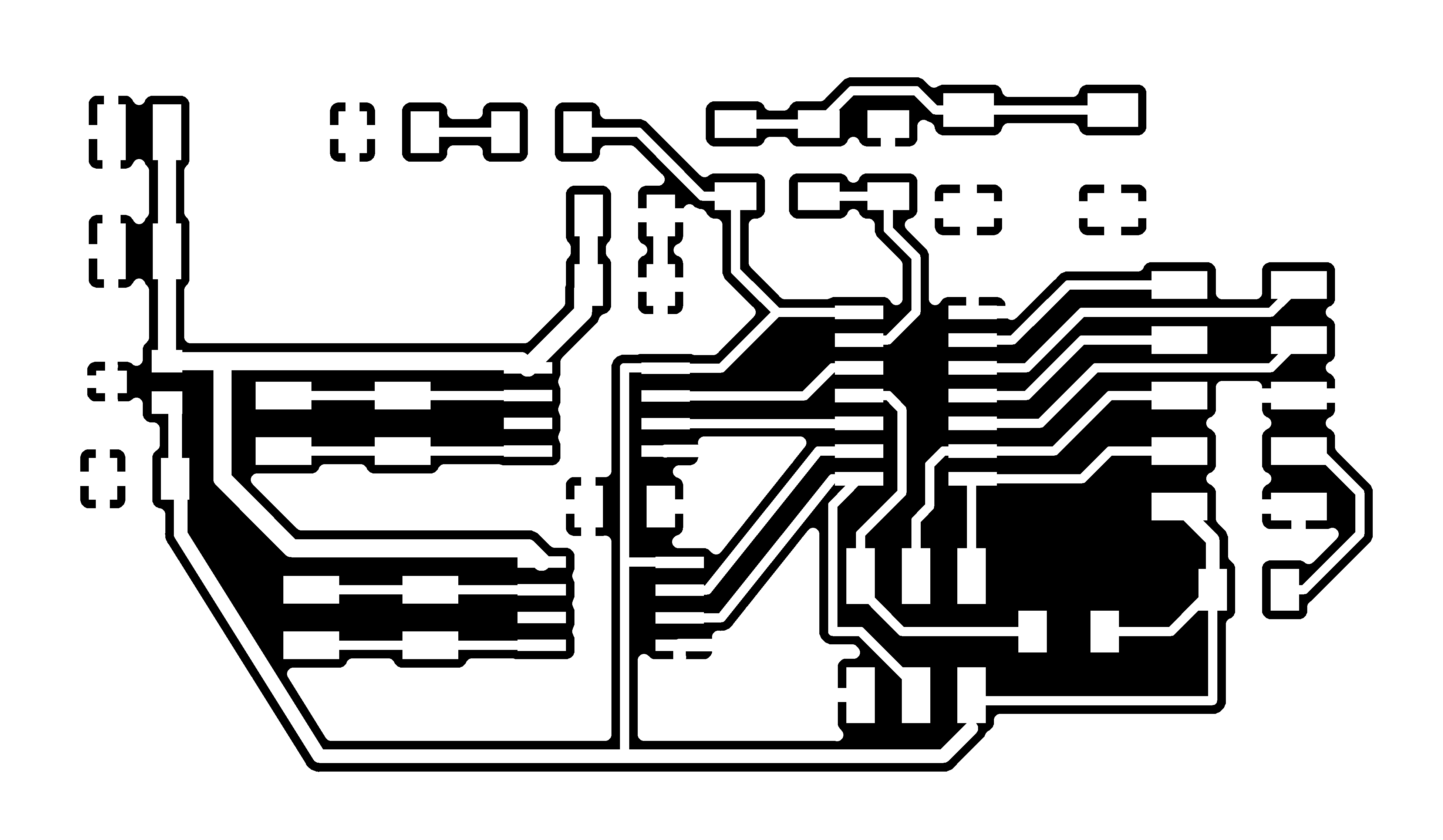
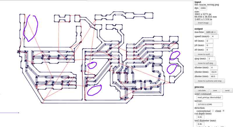
I fabricate the board as I did in week 4, using the Fabmodules to generate the .rml. I created three different files: one for the traces, one for the text and one for cutting out the board. I realized that the GND pads could not be drawn by fabmodules (Figure 12)
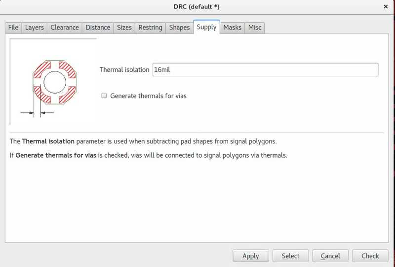
After a lot of trial and error, Antti, one of our monitors, gave me the right solution. In the Design Rule Check I had to modify the Thermal isolation value to 16mils. This would fix the problem, since will increase the width of the separation of the GND pads.
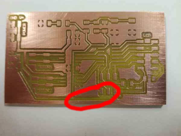
After fabricating the board in the Roland Milling precision machine, I had another problem. The track at the bottom (VCC) was so thin, that it broke while cleaning the board. Hence, I had to repeat the board, increasing the size of that track to 0.022 inches.
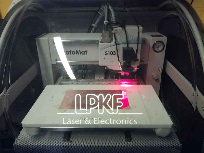
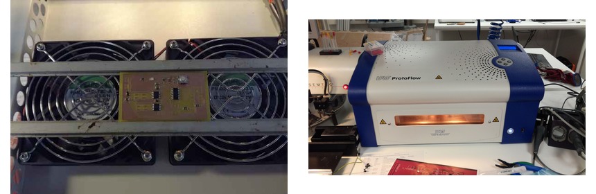
I had no that much time, so I utilized a Jari's professional ProtoMat machine to repeat the milling.
Due to time economy, I used the reflow oven to solder the components. The pins were soldered by hand, though.
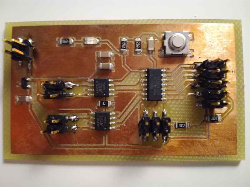
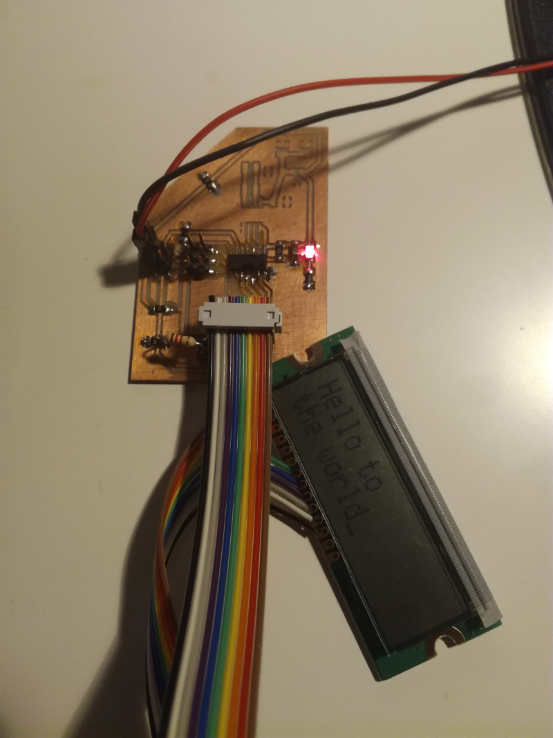
The final resource is shown in Figure 17
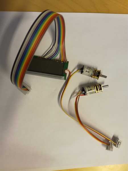
I had also to fabricate the cables to connect the LCD, the motors and the batteries to the PCB. For the LCD I used a ribbon cable (10 wires) with a 2x5 headers. For the motors, I utilized a ribbon cable (4 wires) with a 2x2 connector, while for the battery I utilized a 9V battery case, connected with 2 wires to a 2x2 header connector.
Coding
I decided to divide the task in three different programs: one to test the LCD, one to test the motors and one which integrate both functionalities. I created a make file as I did during week 8. In this case, I had to made some small modifications to the fuses since I am using the internal clock of the microcontroller and I do not want to use a scaler. After reading the right values from the AVR fuse calculator I rewrote the code:
program-usbtiny-fuses: $(PROJECT).hex
  avrdude -p t44 -P usb -c usbtiny -U lfuse:w:0xE2:m
Using the previous makefile I managed to change the fuses of the PCB and program the board.
Problem with the PCB
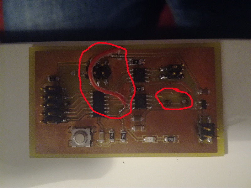
When I try to test the program I realized that something was wrong. My circuit was consuming too much power, but I could not find where could be the problem. I tried powering with a 9V battery and with our Fab Lab power source. I checked for shortcirucit with the multimeter, but I could not find the problem. With the help of a colleage, we realize that the H-Bridge had at the bottom a thermal pad, and it turn out that I decided to run the VCC track just below the H-Bridge. I will continue working with the board trying to solve the issue
Fixing the board
While trying to solve the problem I managed to strip out one of the motor pins, taking with me a lot of the copper. In addition, I tried different workarounds to check if the H-Bridge was the problem. For instance, I cut the power connection of the H-Bridges, and make a jumper with a cable. I tried to run the lcd_test.c but the LCD screen did not even turned on. The power consumption was disminshed though. After a few weeks, I realized that another problem is that I was missing the voltage divider from the VEE pin in the LCD which is the one which regulates the contrast of the screen. Hence, it is clear that the PCB was completely broken and I had to do a new one. This time, due to time constraints I planned to make it simple and that could be used also in the Networking assignment.
Working prototype
I decided to make a simpler prototype with just one button. In this case the screen will show a set of arrows (up, down) and minus sign. The up arrows means that the motor will run forward, the down arrow means that the motor will run backwards and the - sign means that the motor will stop. The design and fabrication process is similar to the one explained before. The following figures present the new diagrams.


This time I first started with Neil's LCD Hello World!. Again did not work. The problem was that the VEE pin was not connected to a tensor divisor, but just to a 100K resistor. Then, it the LCD did not turned on. After, adding a 1.2K resitor (I had to place through whole resistor as seen in Figure 27) I managed to have the example working. Next, is to upload my own code and add the motor components.
LCD memory and instructions
I wrote some code in order to understand how to operate the LCD: for instance, how to turn on / off display or how to move the cursor along the LCD. My goal was to write in the screens certain symbols (mainly arrows) in different positions. I opened the datasheet of the HD44780 LCD controller. My goal is to be able to write arrows and space on the LCD screen.
The HD44780U has two types of memory: DDRAM(Display Data RAM) stores display data represented in 8-bit character codes and the CGRAM/CGROM (Character Generator ROM/RAM) which stores 5 × 8 dot or 5 × 10 dot character patterns from 8-bit character codes. That is, The CGRAM tells how to write a single character, while the DDRAM defines where each character is placed in the LCD screen.
The set of instructions are given in the Figure 28.

The LCD screen controller has the following signals:
- R/S
- Selects if you are going to modify data in any of the memory, or you are sending a new instruction
- E
- Starts data read/write
- R/W
- Informs if you are reading / writing data
- DB4 to DB7
- Four high order bidirectional tristate data bus pins. Used to transfer data between the microcontroller and the LCD
- DB0 to DB3
- Four low order bidirectional tristate data bus pins. Used for data transfer and receive between the microcontroller and the LCD. These pins are not used during 4-bit operation.
The HD44780 LCD controller can send data in either two 4-bit operations or one 8-bit operation:
- For 4-bit interface data, only four bus lines (DB4 to DB7) are used. The data transfer is completed after the 4-bit data has been transferred twice. The four high order bits (for 8-bit operation, DB4 to DB7) are transferred before the four low order bits (for 8-bit operation, DB0 to DB3).
- For 8-bit interface data, all eight bus lines (DB0 to DB7) are used
Since I have a limited pinout, I decided to use the 4 bit option, where the DB0 to DB3 (data bits) are not used and hence not connected to my board.
In order to facilitate writing more code, I decided to use a set of constants in order to define the instructions to be sent. One or two constants together form any of the instructions shown in Figure 28. In addition, I used the routine lcd_putcmd in order to write a command (e.g. init the display or move cursors), lcd_putchar in order to write one char in the current position of the cursor and the routine lcd_putstring to write a whole string
//
// lcd_putcmd
//    put command in lcdbyte. Notice that normally a command has two different inputs.
//
void lcd_putcmd(char lcdbyte) {
   //
   // clear RS for command
   //
   clear(LCD_port, RS);
   //
   // output command bits
   //
   PORTA = lcdbyte;
   //
   // strobe E
   //
   strobe_delay();
   set(LCD_port, E);
   strobe_delay();
   clear(LCD_port, E);
   //
   // wait and return
   //
   lcd_delay();
   }
//
// lcd_putchar
//    put character in lcdbyte
//
void lcd_putchar(char lcdbyte) {

   //
   // set RS for data
   //
   set (LCD_port, RS);
   //
   // output high nibble
   //
   if bit_test(lcdbyte, 7)
      set(LCD_port, DB7);
   else
      clear(LCD_port, DB7);
   if bit_test(lcdbyte, 6)
      set(LCD_port, DB6);
   else
      clear(LCD_port, DB6);
   if bit_test(lcdbyte, 5)
      set(LCD_port, DB5);
   else
      clear(LCD_port, DB5);
   if bit_test(lcdbyte, 4)
      set(LCD_port, DB4);
   else
      clear(LCD_port, DB4);
   //
   // strobe E
   //
   strobe_delay();
   set(LCD_port, E);
   strobe_delay();
   clear(LCD_port, E);
   //
   // wait
   //
   lcd_delay();
   //
   // output low nibble
   //
   if bit_test(lcdbyte, 3)
      set(LCD_port, DB7);
   else
      clear(LCD_port, DB7);
   if bit_test(lcdbyte, 2)
      set(LCD_port, DB6);
   else
      clear(LCD_port, DB6);
   if bit_test(lcdbyte, 1)
      set(LCD_port, DB5);
   else
      clear(LCD_port, DB5);
   if bit_test(lcdbyte, 0)
      set(LCD_port, DB4);
   else
      clear(LCD_port, DB4);
   //
   // strobe E
   //
   strobe_delay();
   set(LCD_port, E);
   strobe_delay();
   clear(LCD_port, E);
   //
   // wait and return
   //
   lcd_delay();
   }

//
// lcd_putstring
//    put a null-terminated string in flash
//
void lcd_putstring(PGM_P message) {
   static uint8_t index;
   static char chr;
   index = 0;
   while (1) {
      chr = pgm_read_byte(&(message[index]));
      if (chr == 0)
         return;
      lcd_putchar(chr);
      ++index;
      }
   }
Code to initialize the screen using just 4 bits
#define DB7 (1 << PA0)
#define DB6 (1 << PA1)
#define DB5 (1 << PA2)
#define DB4 (1 << PA3)
#define INITIALIZATION DB5+DB4
#define LCD_4BITMODE DB5
//
// initialization sequence. Initializing by instruction (other options is via reset circuit: view page 23 of controller)
//
lcd_putcmd(INITIALIZATION);
short_delay();
lcd_putcmd(INITIALIZATION);
short_delay();
lcd_putcmd(INITIALIZATION);
//
// 4-bit interface
//
lcd_putcmd(LCD_4BITMODE);
Initial settings. Display utilizing two lines and 5x7 dot characters
#define SHORT_SETTINGS DB5// Next command will define the number of lines and font

//For lines and font. THIS will go in the initalization after the SHORT_SETTINGS.
#define DB7 (1 << PA0)
#define DB6 (1 << PA1)
#define DB5 (1 << PA2)
#define DB4 (1 << PA3)
#define SHORT_ONELINE_SMALL 0//5x8 points font
#define SHORT_ONELINE_BIG DB6    //5x10 points font
#define SHORT_TWOLINES DB7
//
// two lines, 5x7 font
//
lcd_putcmd(SHORT_SETTINGS);
lcd_putcmd(SHORT_TWOLINES); //Use SHORT_ONELINE_BIG for 5x10 points and SHORT_ONELINE_SMALL for 5x8 poinnts
Activating the screen and the cursor
#define DB7 (1 << PA0)
#define DB6 (1 << PA1)
#define DB5 (1 << PA2)
#define DB4 (1 << PA3)
#define SHORT_DEFAULT_COMMAND 0
//FOR THE LCD ON/OFF. If cursor it will blink
#define SHORT_LCDON_CURSOR DB7+DB6+DB5+DB4
#define SHORT_LCDON_NO_CURSOR DB7+DB6
#define SHORT_LCDOFF DB7
// cursor on
//
lcd_putcmd(SHORT_DEFAULT_COMMAND);
lcd_putcmd(SHORT_LCDON_CURSOR); //Use SHORT_LCDON_NO_CURSOR to remove the cursor and SHORT_LCDOFF to switch off the screen
Settings properties of the cursor. Indicates also if the display should shift or not:
#define DB7 (1 << PA0)
#define DB6 (1 << PA1)
#define DB5 (1 << PA2)
#define DB4 (1 << PA3)
#define SHORT_DEFAULT_COMMAND 0
//for the mode sets
//shifts indicates that the cursor do not move but the whole display
//The direction of the movement (cursor or display) can be left or right
#define SHORT_NOSHIFT_RIGHT DB6+DB5
#define SHORT_NOSHIFT_LEFT DB6
#define SHORT_SHIFT_LEFT DB6+DB4
#define SHORT_SHIFT_RIGHT DB6+DB5+DB4
//
// entry mode
//
lcd_putcmd(SHORT_DEFAULT_COMMAND);
lcd_putcmd(SHORT_NOSHIFT_RIGHT); //Use SHORT_NOSHIFT_LEFT if the cursor should move left, use SHORT_SHIFT_LEFT/SHORT_SHIFT_RIGHT if the screen should shift (instead of the cursor)
Moving the cursor
#define DB7 (1 << PA0)
#define DB6 (1 << PA1)
#define DB5 (1 << PA2)
#define DB4 (1 << PA3)
#define SHORT_DEFAULT_COMMAND 0
//moving the cursor
#define SHORT_CURSOR_LEFT 0
#define SHORT_CURSOR_RIGHT DB6
#define SHORT_SHIFT_LEFT DB7
#define SHORT_SHIFT_RIGHT DB7+DB6
//Move cursor to the right twice
lcd_putcmd(SHORT_MOVE_CURSOR);
lcd_putcmd(SHORT_CURSOR_RIGHT); //Use SHORT_CURSOR_LEFT to move it to the left or SHORT_SHIFT_LEFT/SHORT_SHIFT_RIGHT to move the screen instead of the cursor
lcd_putcmd(SHORT_MOVE_CURSOR);
lcd_putcmd(SHORT_CURSOR_RIGHT);
Other commands to return to the origin or clear the display
#define DB7 (1 << PA0)
#define DB6 (1 << PA1)
#define DB5 (1 << PA2)
#define DB4 (1 << PA3)
#define SHORT_DEFAULT_COMMAND 0
//Other commands
#define SHORT_CLEARDISPLAY DB4
#define SHORT_RETURNHOME DB5
//Remove anything in the display and put the cursor in the origin
lcd_putcmd(SHORT_DEFAULT_COMMAND);
lcd_putcmd(SHORT_CLEARDISPLAY);
lcd_putcmd(SHORT_DEFAULT_COMMAND);
lcd_putcmd(SHORT_RETURNHOME);
Final example. Printing arrows.
Finally, in order to demonstrate that I can write my own code to present data on the LCD screen, I created a simple code that writes the followin content in the LCD screen. Note that spaces and new lines are preserved in the LCD.
← →   ←
 ←
The code uses the constants and instructions presented in the previous paragraph. It can be find completely here
//Initialize the LCD
init_lcd();

//load the arrows

//Go to zero position
lcd_putcmd(SHORT_DEFAULT_COMMAND);
lcd_putcmd(SHORT_RETURNHOME);
//Print arrow and space
lcd_putchar(0x7E);//left
lcd_putchar(0x20); //space
lcd_putchar(0x7F); //right
lcd_putchar(0x20);//space

//Move cursor to the right
lcd_putcmd(SHORT_MOVE_CURSOR);
lcd_putcmd(SHORT_CURSOR_RIGHT);
lcd_putcmd(SHORT_MOVE_CURSOR);
lcd_putcmd(SHORT_CURSOR_RIGHT);

lcd_putchar(0x7E);//left
lcd_putchar(0x20); //space

lcd_putcmd(SHORT_MOVE_CURSOR);
lcd_putcmd(SHORT_SHIFT_LEFT);

lcd_putcmd(SHORT_NEXT_LINE_1);
lcd_putcmd(SHORT_NEXT_LINE_2);

lcd_putchar(0x20); //space
lcd_putchar(0x7E);//left
lcd_putchar(0x20); //space
Resources utilized
- Electronic components from Fab inventory
- 16x2 LCD screen
- CNC router Roland GSR-20 to print the circuits
- Autodesk Eagle to draw the circuits
- Oscilloscope to check signals coming from the microcontroller to the LCD screen.
Circuits and Code
Initial design
- Eagle's schematics
- Eagle's board file
- The traces, cutout and text layer rml files for Roland machines
- lcd_test.c and its make: lcd_test.c.make (Could not be tested)
Working prototype
- Eagle's schematics
- Eagle's board file
- LCD Hello world and its make file as well as the avrdude_gpip.conf file I used to program it with Raspberri Pi. This code is basically the same as Neil's LCD Hello World!
- LCD program showing arrows in the screen and its make file as well as the avrdude_gpip.conf file I used to program it with Raspberry Pi. This code is heavily based on Neil's LCD Hello World!. However, I added a lot of clarifications, and constants to make easier its modification.