
Week 8. Embedded programming
During this week I implemented and deployed several applications to the ATTiny microcontroller
Tasks
- Read a microcontroller datasheet
- Implement several applications for the ATtiny microcontroller
- Program the microcontroller
Process explanation
Microcontroller datasheet
During this week I have gone through 2 different AVR microcontroller datasheets:
- ATTiny 44 datasheet. This is my PCBs microcontroller. I have mainly focused in the general architecture of the system: Chapters 1, 2 and 3, memory programming (section 19) and I/O ports (section 10).
- ATmel 328P datasheet. This is Arduino Uno microcontroller. I have to read this for an introductory course to embedded programming that I am currently teaching. In this case went through all the sections, but without paying too much attention to the detais. Mainly reading the introduction of each section. This microcontroller offers more features than the ATTiny 44. For instance it has support for I2C, SPI and UART while the ATTiny 44 just support SPI.
Program the microcontroller
Building ISP cable
During week 4 and week 6 I utilized a cable that I found in FabLab to program my PCBs. However, this week I decided to build my own cable. I followed the next steps:
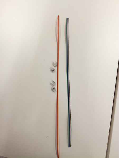
- Take a 9-way ribbon cable (from FabLab inventory) and remove three lines. Take also the SPI headers and the covers.
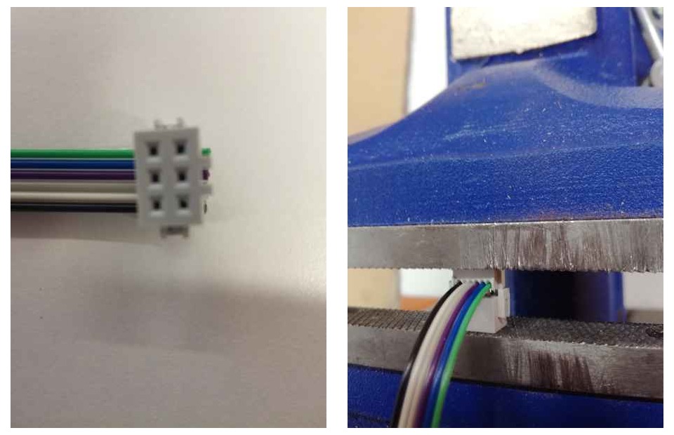
- Place the cable inside the header. The header had some guides to accomodate the cable. Next, you need to close the header. There are some crampers for that purpose, however I do not have them available, so I utilized a table clamp to apply pressure on the header to close them. Please, note that you need to fasten very gently the header.Otherwise, it can easily break (actually it happened to me once)
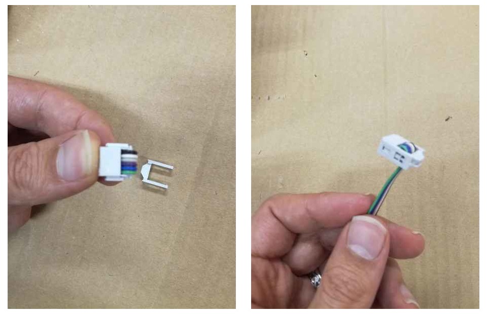
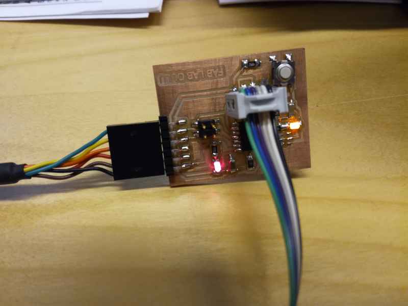
- Finally, I placed the header cover, in the way is shown in Figure 3. Please, note how the cable is positioned before attaching the cover.
Programming the board
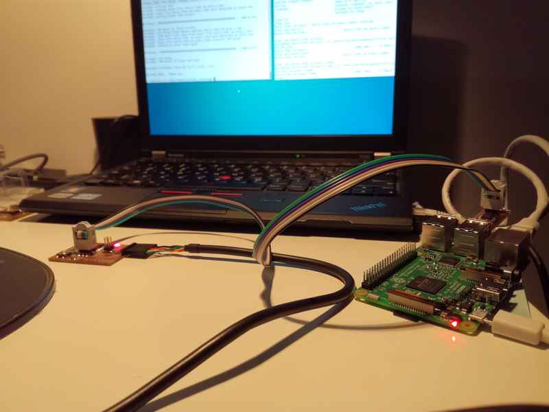
I continued to use Ubuntu Linux to code, compile and upload code to the PCBs as I did during week 4 and week 6. However, this week, instead of using my own computer I utilized a Raspberry Pi 3 Model B running a Pi adapted version of Ubunutu Mate 16.04. Actually, the idea is not originally mine but I followed Mikko's advice. Since I am using my own hardware to program the boards, and I do not trust that much yet in my soldering / electronic design skills, it would be better to damage due to a short circuit a raspberry pi (~50€) than my own laptop (~1200€) due to a short circuit
I downloaded Ubuntu Mate to my PC and then moved to a SD card using the sudo ddrescue -D --force command(as explained in Ubuntu Mate for Raspberri 3 website. Then I had to connect the Raspberri Pi to a display through the HDMI port for (1)Enabling the ssh; (2)Configuring my wireless network; (3)Configurin the wired network as Local link. Then I connected my computer with the Pi using an Ethernet cable (my PC network was also configured as Local link). After that I could open ssh and sftp connections to the Pi from my computer to send commands and files: ssh name_of_my_pi or sftp name_of_my_pi. Since several devices should be connected at the same time to the Pi, and it should be able to power at least two boards (my PCB and the programmer) I was utilizing a 2A charger to power the device.

I installed the following software via sudo apt-get install:
- avrdude:Open-source command line tool for reading, writing and manipulating AVRs using the in-system programming technique (ISP). This tool permits, for instance, checking the target microcontroller signature as well as writting a hex file to AVR's Flash memory (that is programming the microcontroller) using a programmer.
- gcc-avr:A GNU C cross compiler for AVR.
- binutils-avr: Binutils library that accepts AVR as a target. Binutils basically contains a linker and an assembler.
- avr-libc:C library specially tailored to AVR microcontrollers
- make: GNU utility which twhich controls the generation of executables and other non-source files of a program from the program's source files.
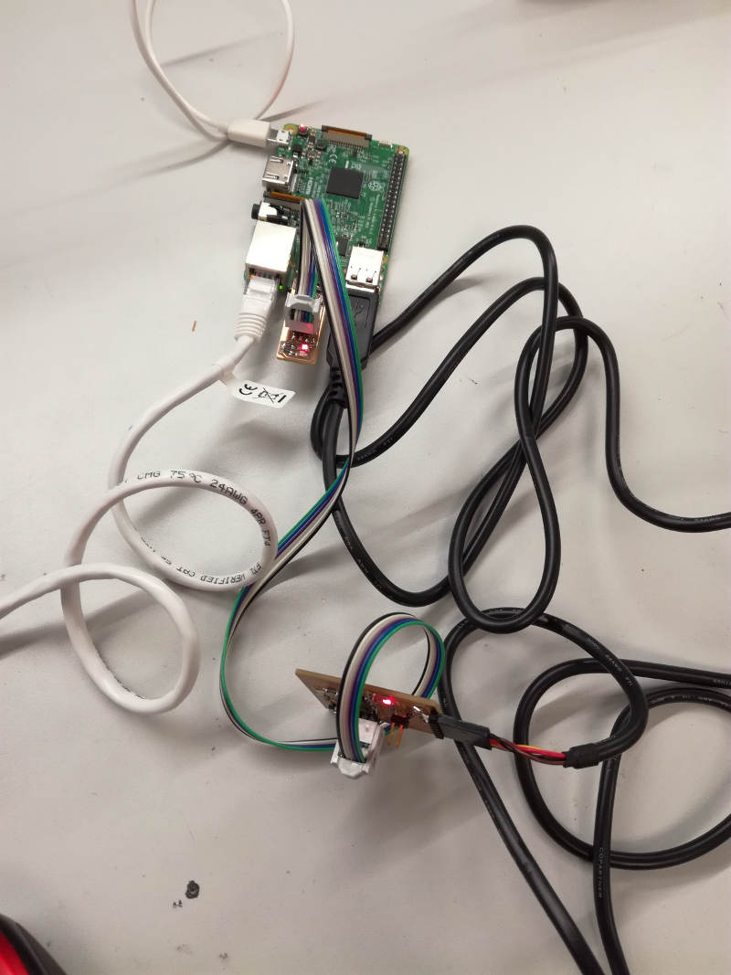
Since this is the first time, I really use my own programmer to write code in the AVR, I would like to try something that I know that was working from Week 6, so I uploaded the echo example application from and compiled in the Pi. Then, I connected the programmer to the USB port of the Pi, connected the PCB to the programmer via the SPI bus and finally, connected my computer with the PCB using a USB-to-FTDI cable. In this case, I used my computer to echo the data via the python terminal app. I run the following commands to compile, program and test the board:
make -f hello.ftdi.44.echo.c.make: Compile the codesudo make -f hello.ftdi.44.echo.c.make program-usbtiny-fuses: Setting up the microcontroller for programmingsudo make -f hello.ftdi.44.echo.c.make program-usbtiny: Flash the microcontroller
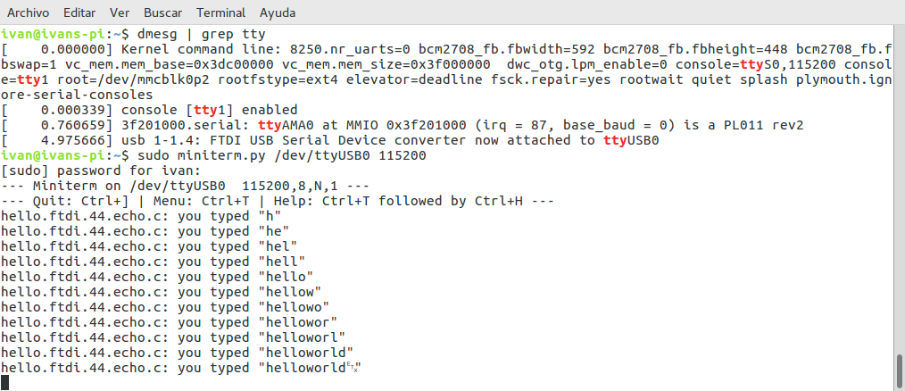
Fortunately, everything worked as shown in Figure 6.

I disconnected the FTDI cable from my computer and connected to the Pi. I wanted to check if I could do the same using just the Pi and a ssh connection. I opened a serial communication with the device using miniterm.py application that is included in pyserial python package.
And this is what I saw:
After that I wanted to understand how avrdude works. Following the instructions I found in one internet tutorial I first wanted to check that the device was correctly initialized and get its signature. In the avrdude I just have to specify the PCB microcontorller (t44) and the programmer (usbtiny).The result is sown below
ivan@ivans-pi:~home$ avrdude -p t44 -c usbtiny

avrdude: AVR device initialized and ready to accept instructions

Reading | ################################################## | 100% 0.01s

avrdude: Device signature = 0x1e9207 (probably t44)

avrdude: safemode: Fuses OK (E:FF, H:DF, L:5E)

avrdude done.  Thank you.
After that I wanted to check how the fuses were programmed. I used this online fuse calcultor in order to see which are the possible values you can modify with the fuses. In addition, I read the section 19.2 ATTiny44 data sheet in order to understand the meaning of the different bits. Please note that programming a fuse bit, means to put it to 0 and unprogramme it means put it to 1. With the fuses you can select, among other, following settings:
- Clock to be used. Since we want to use an external clock we need to modify the fuses. Accordding to section 6.2 in ATTiny44 data sheet, you need to set the CKSEL bits to 0 (CKSEL=1110)
- When external clock source is selected, start-up times are determined by the SUT Fuses as shown in table 6.3 from ATTiny Data Sheet. In this case, I used the default settings coming in the fuse calculator, that turn out to be the most conservative ones, recommended for "Slowly rising power". The SUT fuses were set to 01
- Initial clock preescaler. If CKDIV8 fuse is programmed (CKDIV8=0, then, by default any external clock is divided by 8. That is, accordding to section 6.5.2 of the ATTiny44 data sheet "the divider divides the master clock input to the MCU, the speed of all synchronous peripherals is reduced when a division factor is used." "The Application software must ensure that a sufficient division factor is chosen if the selcted clock source has a higher frequency than the maximum frequency of the device at the present operating conditions". The frequency preescaler can be modified later using the CLKPS register.
- Allow the clock signal to be an output in a data pin. Currently it is disabled: CKOUT=1
- Enable SPI and data downloading by setting the SPIEN fuse to 0
- Activate the Brown-out detection, that is, a dip in the power supply voltage. If it happens, the microcontroller automatically reset. Setting the BODLEVEL fuses accordding to table 20.5.2 in the ATTiny44 data sheet. Actually, I am not plannig to use this feature so I kept the default values: 111
I left the rest of the values to its default value. Inserting the values from the this online fuse calcultor, I got the following values for the fuse bits to use in the avrdude command:
-U lfuse:w:0x5e:m
-U hfuse:w:0xdf:m
-U efuse:w:0xff:m
Note that accordding avrdude documentation it means:
- I am writing in memory: -U parameter
- I am accessing/modifying the lfuse/hfuse/efusememory
- I am performing a writing operation: the w parameter
- I am using the immediate mode; actual byte values specified on the command line (m parameter). This is useful to programming bits
I then executed the command to set the lfuse its right value:
                    ivan@ivans-pi:~home$ avrdude -p t44 -c usbtiny -U lfuse:w:0x5e:m
avrdude: AVR device initialized and ready to accept instructions

Reading | ################################################## | 100% 0.01s

avrdude: Device signature = 0x1e9207 (probably t44)
avrdude: reading input file "0x5e"
avrdude: writing lfuse (1 bytes):

Writing | ################################################## | 100% 0.00s

avrdude: 1 bytes of lfuse written
avrdude: verifying lfuse memory against 0x5e:
avrdude: load data lfuse data from input file 0x5e:
avrdude: input file 0x5e contains 1 bytes
avrdude: reading on-chip lfuse data:

Reading | ################################################## | 100% 0.00s

avrdude: verifying ...
avrdude: 1 bytes of lfuse verified

avrdude: safemode: Fuses OK (E:FF, H:DF, L:5E)

avrdude done.  Thank you.
Finally, I wanted to check if I could compile an application using avr-gcc and program the controller using avr-dude and hence avoiding to use the provided makefile. I downloaded the echo.interrupt.c example. And run:
ivan@ivans-pi: avr-gcc -mmcu=attiny44  -Wall -Os -I. -o hello.ftdi.44.echo.interrupt.out hello.ftdi.44.echo.interrupt.c

In file included from hello.ftdi.44.echo.interrupt.c:21:0:
/usr/lib/avr/include/util/delay.h:90:3: warning: #warning "F_CPU not defined for <util/delay.h>" [-Wcpp]
# warning "F_CPU not defined for <util/delay.h>"
The parameters used with the avr-gcc : commands were:
-Wall: Activate all warnings-mmcu: The target microcontroller-Os: Activate maximum optimization of the size in code-I.: Uses the current directory to search for the header files-o: Defines teh output file
Note that it gave me a warning since I did not defined a property F_CPU. Hence, I defined it as a command-line argument using the -D option:
avr-gcc -mmcu=attiny44 -Wall -Os -DF_CPU=20000000 -I. -o hello.ftdi.44.echo.interrupt.out hello.ftdi.44.echo.interrupt.c
This compiled the code into a C .o file. I need to transform this into an .hex file using the avr-objcopy command:
avr-objcopy -O ihex hello.ftdi.44.echo.interrupt.out hello.ftdi.44.echo.interrupt.c.hex
I used the following parameters:
- -O ihex tells the expected output format. In this case ihex means that we want a binary file in hexadecimal. But we could have also binary there.
This generated the .hex file output. I noticed that the example's makefile used also the avr-size command. This utility informs about the size in memory of a given file.
ivan@ivans-pi:avr-size --mcu=attiny44 --format=avr hello.ftdi.44.echo.interrupt.out
AVR Memory Usage
----------------
Device: attiny44

Program:     832 bytes (20.3% Full)
(.text + .data + .bootloader)

Data:         74 bytes (28.9% Full)
(.data + .bss + .noinit)
I used the following parameters:
- -mcu: the microcontroller I am using
- -format: the format of the output. Ohter possible values are SysV or Berkley
when I had my hex file ready I used the avr-dude to upload the program to my PCB:
ivan@ivans-pi: avrdude -p t44 -P usb -c  usbtiny -U flash:w:hello.ftdi.44.echo.interrupt.c.hex


avrdude: AVR device initialized and ready to accept instructions

Reading | ################################################## | 100% 0.01s

avrdude: Device signature = 0x1e9207 (probably t44)
avrdude: NOTE: "flash" memory has been specified, an erase cycle will be performed
         To disable this feature, specify the -D option.
avrdude: erasing chip
avrdude: reading input file "hello.ftdi.44.echo.interrupt.c.hex"
avrdude: input file hello.ftdi.44.echo.interrupt.c.hex auto detected as Intel Hex
avrdude: writing flash (832 bytes):

Writing | ################################################## | 100% 0.51s

avrdude: 832 bytes of flash written
avrdude: verifying flash memory against hello.ftdi.44.echo.interrupt.c.hex:
avrdude: load data flash data from input file hello.ftdi.44.echo.interrupt.c.hex:
avrdude: input file hello.ftdi.44.echo.interrupt.c.hex auto detected as Intel Hex
avrdude: input file hello.ftdi.44.echo.interrupt.c.hex contains 832 bytes
avrdude: reading on-chip flash data:

Reading | ################################################## | 100% 0.84s

avrdude: verifying ...
avrdude: 832 bytes of flash verified

avrdude: safemode: Fuses OK (E:FF, H:DF, L:5E)

avrdude done.  Thank you.
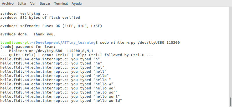
To check that it was working I used miniterm.py application to connect using the serial port:
sudo miniterm.py /dev/ttyUSB0 115200
Obtaining the following results:
Implement software for the ATTiny44
Using C
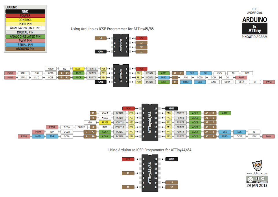
The pinout of microcontroller is shown in the following figure:
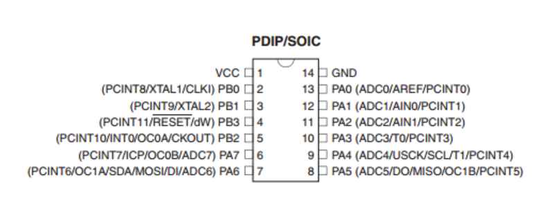
The pinout is a must to know which pins you need to use as input and as outputs. In my case, I had my LED in pin 5 (PB2)
Section 10 of the ATTiny44 data sheet explains I/O. We have two different ports: PORTA and PORTB. Each port is composed with 3 different type of registers:
- DDRx: It indicates the direction of the pins. Each bit represent a pin: DDx0 => pin0, DDx1=>pin1, DDx2 => pin2 and DDx3 => pin3. (The same happens with PORTA)
- PORTx: Port data register. Used to set the pin value to 0 (LOW) or 1 (HIGH). Each bit represents one pin (see DDRx before).
- PINx:Port input pins. To read pin values. Each Pin is represented by a bit (as in DDRx and PORTx).
Another important aspect is how to set, unset and read the values of different ports. I am using the following syntax:
 //Set one register value:
Rx = Rx | (1<<pin); //Where RX is the register name and pin is the pin to be modified

// Unset one register value
Rx = Rx & ~(1<<pin);//Where RX is the register name and pin is the pin to be modified

// Check if one bit of the register is set to 1
RX & (1 <<bit)//Where RX is the register name and pin is the pin to be modified. It returns 1 or 0 depending if the value is set or not.
I created a make file (See Code section) to speed up the testing process. The code can be found in the code section. I compiled and uploaded the code to my board and it is working as it can be seen in Figure 10. However, I found a problem that I still have not resolved. If i setup a delay of 1000 ms (using the _delay_ms() function, actually the real delay is 100ms. Hence, if I want a delay of 1000ms I need to write _delay_ms(100). I thought that might be a type with the clock frequency (e.g. in the F_CPU variable), but I revised it several times and it looks correct. I am still looking for the information.
make -f blink.make program-usbtiny-fuses
                       make -f blink.make prograpm-usbtiny
Next step is to start the LED while pressing the button. The code is shown in the Code section. This time the code worked without any problem
Programming with the Pi without a programmer
Next step was using the Raspberri Pi as a programmer using 6 pins of the Pi's GPIO as the pins realizing the SPI programming interface. The pinout of the Pi and the Pins I am using for the SPI is shown in Figure 11.
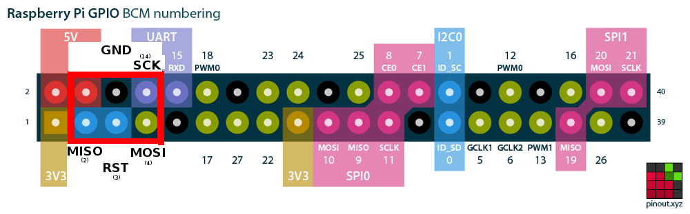
I had to build my own cable in order to map correctly the pins from the SPI interface at the microcontroller and the SPI in the Pi. Notice that I could not match one-to-one because of the position of the GND. Moreover, I realized that I connected the Pi's VCC to the SPI VTG in the board. It is wrong because VTAG is just an output to the programmer, not an input.. Hence, I had to physically remove the cable from the header (the cable was already built)

My goal is to program the pins of the Pi so they act as an ouput of the SPI interface:
- Board's GND to Raspberry Pi ground pin.
- Board's RESET to Raspberry Pi GPIO #3.
- Board's SCK to Raspberry Pi GPIO #14.
- Board's MOSI to Raspberry Pi GPIO #4.
- Board's MISO to Raspberry Pi GPIO #2.
I followed this tutorial . The configuration can be set in the /etc/avrdude.conf location. Actually, instead of editing the file I copied into the same folder as I had the makefiles. I appended to the file the following lines:
programmer
  id    = "rasp_pi_1";
  desc  = "Use the Linux sysfs interface to bitbang GPIO lines";
  type  = "linuxgpio";
  reset = 3;
  sck   = 14;
  mosi  = 4;
  miso  = 2;
;
The field id will be used by the avrdude -p parameter to identify this configuration in the file.

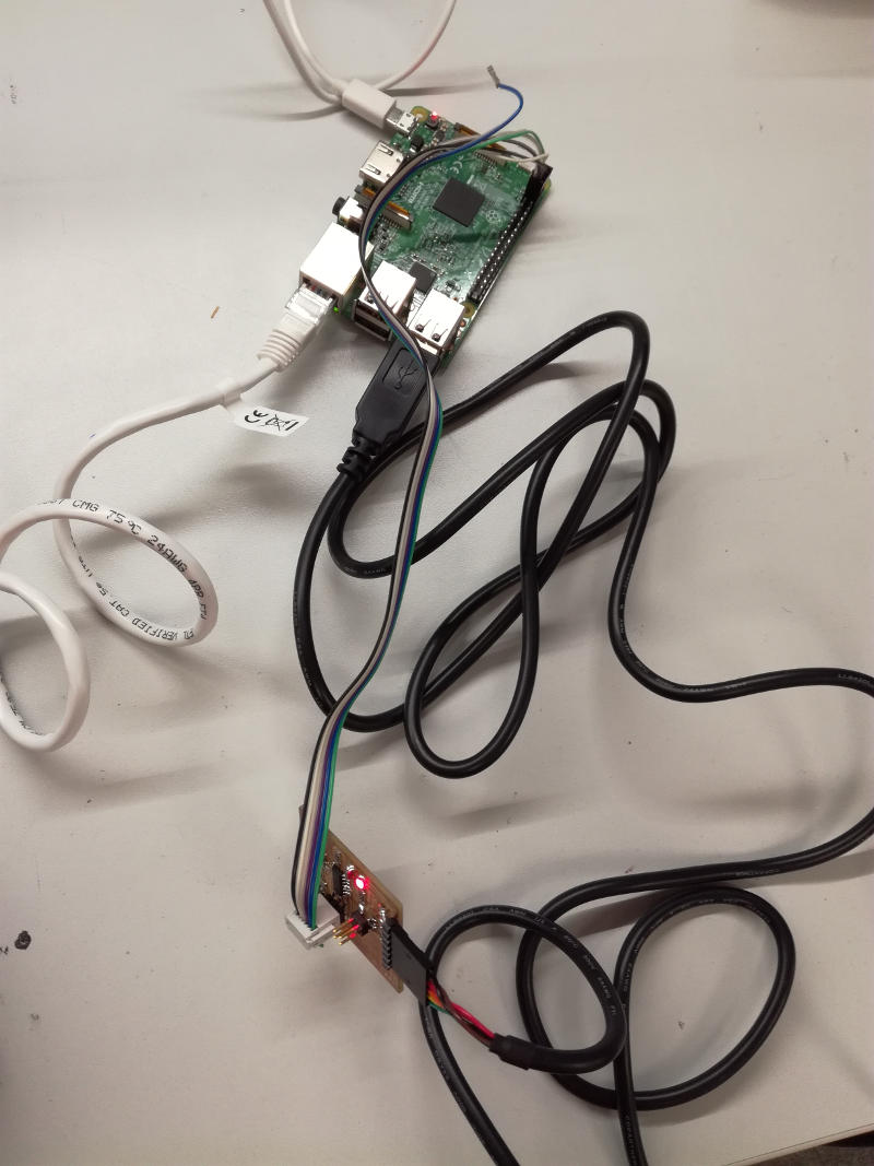
After connecting the programmer cables and the FTDI cable (Figure 13) and trying to verify with avrdude that the connection is correct I found the following error
sudo avrdude -p t44 -P usb -C ./avrdude_gpip.conf -c rasp_pi_1 -v

avrdude: Version 6.2
         Copyright (c) 2000-2005 Brian Dean, http://www.bdmicro.com/
         Copyright (c) 2007-2014 Joerg Wunsch

         System wide configuration file is "./avrdude_gpip.conf"
         User configuration file is "/home/ivan/.avrduderc"
         User configuration file does not exist or is not a regular file, skipping

         Using Port                    : usb
         Using Programmer              : rasp_pi_1
Can't export GPIO 3, already exported/busy?: Device or resource busy
avrdude done.  Thank you.
I restarted the Raspberri Pi. I executed again the command and this time I could get the verification
avrdude -p t44 -P usb -C ./avrdude_gpip.conf -c rasp_pi_1 -v

avrdude: Version 6.2
         Copyright (c) 2000-2005 Brian Dean, http://www.bdmicro.com/
         Copyright (c) 2007-2014 Joerg Wunsch

         System wide configuration file is "./avrdude_gpip.conf"
         User configuration file is "/home/ivan/.avrduderc"
         User configuration file does not exist or is not a regular file, skipping

         Using Port                    : usb
         Using Programmer              : rasp_pi_1
         AVR Part                      : ATtiny44
         Chip Erase delay              : 4500 us
         PAGEL                         : P00
         BS2                           : P00
         RESET disposition             : possible i/o
         RETRY pulse                   : SCK
         serial program mode           : yes
         parallel program mode         : yes
         Timeout                       : 200
         StabDelay                     : 100
         CmdexeDelay                   : 25
         SyncLoops                     : 32
         ByteDelay                     : 0
         PollIndex                     : 3
         PollValue                     : 0x53
         Memory Detail                 :

                                  Block Poll               Page                       Polled
           Memory Type Mode Delay Size  Indx Paged  Size   Size #Pages MinW  MaxW   ReadBack
           ----------- ---- ----- ----- ---- ------ ------ ---- ------ ----- ----- ---------
           eeprom        65     6     4    0 no        256    4      0  4000  4500 0xff 0xff
           flash         65     6    32    0 yes      4096   64     64  4500  4500 0xff 0xff
           signature      0     0     0    0 no          3    0      0     0     0 0x00 0x00
           lock           0     0     0    0 no          1    0      0  9000  9000 0x00 0x00
           lfuse          0     0     0    0 no          1    0      0  9000  9000 0x00 0x00
           hfuse          0     0     0    0 no          1    0      0  9000  9000 0x00 0x00
           efuse          0     0     0    0 no          1    0      0  9000  9000 0x00 0x00
           calibration    0     0     0    0 no          1    0      0     0     0 0x00 0x00

         Programmer Type : linuxgpio
         Description     : Use the Linux sysfs interface to bitbang GPIO lines
         Pin assignment  : /sys/class/gpio/gpio{n}
           RESET   =  3
           SCK     =  14
           MOSI    =  4
           MISO    =  2

avrdude: AVR device initialized and ready to accept instructions

Reading | ################################################## | 100% 0.00s

avrdude: Device signature = 0x1e9207 (probably t44)
avrdude: safemode: hfuse reads as DF
avrdude: safemode: efuse reads as FF

avrdude: safemode: hfuse reads as DF
avrdude: safemode: efuse reads as FF
avrdude: safemode: Fuses OK (E:FF, H:DF, L:5E)

avrdude done.  Thank you.
I realized that if I did not executed sudo before calling any avrdude command the system fails (normal user do not have access to GPIO ports). After that, the ports seems to kept open. Following calls to avrdude fails. Only solution I found till now was restarting the Pi.
I wrote new tasks in the makefiles in order to program the board using the Raspberri pi. Basically are calls to the avrdude, utilizing the -C option to load the configuration files where the pinout is defined. After running the command to install the blink application, I succeed with the following ouptut:
sudo make -f blink_py.make program-rasppi
avr-objcopy -O ihex blink.out blink.c.hex;\
avr-size --mcu=attiny44 --format=avr blink.out
AVR Memory Usage
----------------
Device: attiny44

Program:     100 bytes (2.4% Full)
(.text + .data + .bootloader)

Data:          0 bytes (0.0% Full)
(.data + .bss + .noinit)


avrdude -p t44 -P usb -C ./avrdude_gpip.conf -c rasp_pi_1 -U flash:w:blink.c.hex

avrdude: AVR device initialized and ready to accept instructions

Reading | ################################################## | 100% 0.00s

avrdude: Device signature = 0x1e9207 (probably t44)
avrdude: NOTE: "flash" memory has been specified, an erase cycle will be performed
         To disable this feature, specify the -D option.
avrdude: erasing chip
avrdude: reading input file "blink.c.hex"
avrdude: input file blink.c.hex auto detected as Intel Hex
avrdude: writing flash (100 bytes):

Writing | ################################################## | 100% 0.08s

avrdude: 100 bytes of flash written
avrdude: verifying flash memory against blink.c.hex:
avrdude: load data flash data from input file blink.c.hex:
avrdude: input file blink.c.hex auto detected as Intel Hex
avrdude: input file blink.c.hex contains 100 bytes
avrdude: reading on-chip flash data:

Reading | ################################################## | 100% 0.06s

avrdude: verifying ...
avrdude: 100 bytes of flash verified

avrdude: safemode: Fuses OK (E:FF, H:DF, L:5E)

avrdude done.  Thank you.
Following the same procedure I installed the blink_button application
Using Arduino IDE.
I wanted to check if I could use Arduino IDE for programming. I first installed Arduino IDE in my Raspberri Pi:
sudo apt-get install arduino
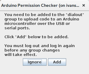
After accepting to be included in the
dialoutgroup to be able to upload files to arduino via USB (although I do not think I am going to needed it) I got Arduino up and running
However, it was an old version 1.0.5 vs the recent 1.6. So what I did was download it directly in my /opt/ folder. I downloaded the version 1.6.12 for ARM devices from https://downloads.arduino.cc/arduino-1.6.12-linuxarm.tar.xz. After uncompress it and install it, I could start Arduino IDE. Note that it requires a Java 8 Runtime Environment, however, it was installed when the IDE was installed from the repository
                  sudo wget https://downloads.arduino.cc/arduino-1.6.12-linuxarm.tar.xz

                  sudo tar -xvf arduino-1.6.12-*.tar.xz

                  cd arduino-1.6.12/

                  chmod +x install.sh

                  ./install.sh

                  ./arduino

                  ./arduino &
I then followed the instructions provided in http://highlowtech.org/?p=1695 to be able to program the AVRTiny family utilizing the Arduino IDE:
- Open the File > Preferencersdialog in the Arduino software.
- Paste the following URL into the field with label "Additional Boards Manager URLs":https://raw.githubusercontent.com/damellis/attiny/ide-1.6.x-boards-manager/package_damellis_attiny_index.json
- Press OK
- Open Tools > Board > Board Manager
- Find in the resulting list the Board Manager that reads : attiny by David A. Mellis. Select the latest version (in my case 1.0.2) and press Install button
- Close the board manager.
- Now you can select the ATTiny 44 from the Board > Tools


The clock fuses can be programmed directly from Arduino IDE
- Go to Tools > Board > Clock
- When the right speed is selected go to Tools > Burn Bootloader
Using the Raspberri Pi as a programmer.
The first step is to configure the IDE so it detects the Raspberry Pi as a programmer. I got inspired by this blog post and the arduino-linuxgpio library from github.
                    /opt/arduino-1.6.12/hardware/tools/avr/bin$ sudo avrdude -c?type

                    ....
                    jtagmkii_pdi     = Atmel JTAG ICE mkII in PDI mode
  jtagice3         = Atmel JTAGICE3
  jtagice3_pdi     = Atmel JTAGICE3 in PDI mode
  jtagice3_dw      = Atmel JTAGICE3 in debugWire mode
  jtagice3_isp     = Atmel JTAGICE3 in ISP mode
  linuxgpio        = GPIO bitbanging using the Linux sysfs interface
  par              = Parallel port bitbanging
  pickit2          = Microchip's PICkit2 Programmer
  serbb            = Serial port bitbanging
  stk500           = Atmel STK500 Version 1.x firmware
  stk500generic    = Atmel STK500, autodetect firmware version

                   ....
If the list includes the linuxgpio everything should be OK.
Next we need to edit Arduino's avrdude.conf file. It is located at: Arduino IDE folder/hardware/tools/avr/etc/avrdude.conf. Find the lines of code that program the linuxgpio. Uncomment them and edit the right pins (as we did in previous steps):
                    programmer
  id    = "linuxgpio";
  desc  = "Use the Linux sysfs interface to bitbang GPIO lines";
  type  = "linuxgpio";
  reset = 3;
  sck   = 14;
  mosi  = 4;
  miso  = 2;
;
After that, we need to add the linuxgpio in Arduino programmer's list. It is located in Arduino IDE folder/hardware/arduino/avr/programmers.txt. We just need to add the following lines in the begining of the file and save it.
                    linuxgpio.name=Linux GPIO / RasPi
linuxgpio.protocol=linuxgpio
Close Arduino IDE and restart it as root. It is necessary to use the Pi GPIO lines. I connected the board as shown in Figure 18. However it did not work. I got the following error message:
Error while burning bootloader.
Can't export GPIO 3, already exported/busy?: Invalid argument
I then decided to stop with that. I will try to find the solution to the problem later.

I decided to stop trying and I started using my FabISP as a programmer.
Using the FabISP as a programmer.
I will use my FabISP programmer that I built on week 4 as a programmer. I connected the programmer and the FTDI cable to two of the Raspberri Pi ports. I connected my board to the ISP interface of the FabISP programmer and the FTDI cable to power it up.
Then select Tools > Programmer > USBTiny . After that I was able to burn the bootloader (actually, this option is a little bit misleading, because the only thing is that is to modify the fuses so the PCB uses the right clock source and speed).
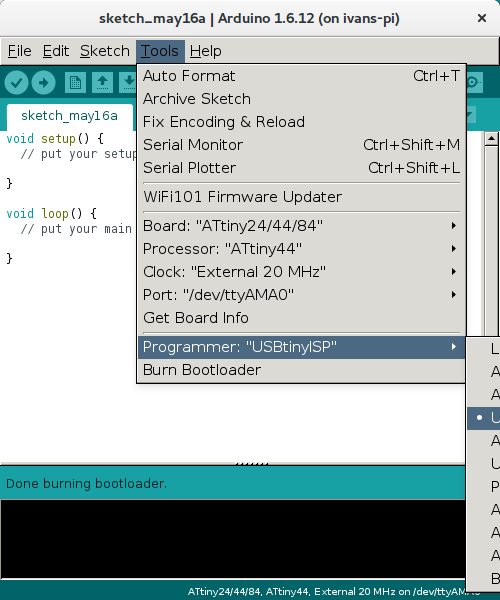
In order to program the board using the Arduino IDE I will use Figure 22. Note that the Arduino pinout for the ATTiny 44 is different than the official pinout from the official datasheet.
I created the following sketch to make the LED blink every second. Note that I am using, in this case the internal clock. To that end I setup 8MHz in the Tools > Clock and after that Burn the bootloader to modify the fuses.
                    const int LEDPIN = 8;
void setup() {
  pinMode (LEDPIN, OUTPUT);

}

void loop() {
    digitalWrite(LEDPIN, HIGH);
    //Wait for 1000ms
    delay(1000);
    digitalWrite(LEDPIN, LOW);
    //Wait for 1000ms
    delay(1000);
}
The code was uploaded and run correctly in the PCB.
Next, I run the code to turn on the LED just when the button is pressed. The code I run was the following:
const int LEDPIN = 8;
const int BUTTONPIN = 7;

void setup() {
  // LED as an output while button as an input
  pinMode(LEDPIN, OUTPUT);
  pinMode(BUTTONPIN, INPUT);
}

void loop() {
  //Check if button is pressed (its value is 0 because the button has a PULL-UP resistor)
  int button = digitalRead(BUTTONPIN);
  if (button == LOW){
    digitalWrite(LEDPIN, HIGH);
  }
  else {
    digitalWrite(LEDPIN, LOW);
  }

}
Resources utilized
- Rasbperry Pi 3 Model B: to program the PCBs
- Ubuntu Mate version tailored for the Raspberri Pi: as a OS for the Raspberri Pi.
- avrdude, avr-libc and gcc-avr: to program the microcontroller
Reflection
Summary
During this week I learnt to create basic programms for an AVR microcontroller in C.
Main learnings
I finally understood the concept of toolchain, and what is the software necessary to develop for AVR microcontroller. Furthermore, I review C basic syntax that I had clearly forgotten. I also learnt the correct way of playing with the & and | to set, unset and read values from microcontroller pins.
Finally, I also learnt how to develop for a microcontroller using a Raspberri Pi as development environment. Actually, it is quite handy because I set up everything on the Pi and I can program the microcontrollers from any computer. I managed to configure the Raspberri Pi as a programmer.
Main difficulties
Not big difficulties in this assignment, but the lack of time. It has been a really busy week for me because of other commitments and I did not have enough time to work as I would have liked in this assignment. Perhaps, the most difficult part is to set up the environment utilizing the Raspberry Pi
Code
- blink.c
- blink.make
- blink_pi.make (for using the Pi as programmer)
- blink.hex
- blink_button.c
- blink_button.make
- blink_button_pi.make (for using the Pi as programmer)
- blink_button.hex
- avrdude_gpio.conf (Configuration file for using the Pi as programmer)
- blink_button_arduino_ide sketch
- blink_arduino_ide sketch