- make lasercutter test part(s), varying cutting settings and slot dimensions
- cut something on the vinylcutter
- design, make, and document a parametric press-fit construction kit, accounting for the lasercutter kerf, which can be assembled in multiple ways
Group Assignment
Together with Iván Sánchez Milara and Jari Pakarinen, we practiced laser cutting, tested how well manufacturer recommended settings for 3mm acryl work in practice and measured the impact of the settings on kerf.
As we were instructed earlier, using the laser cutter requires the following steps:
- Switch on the machine
- Turn on air filtering
- Use joystick to set the origin, Jog, upper left corner of the document
- Use the metal triangular tool and moving laser cutter bed to set the right Focus to (make sure the distance between the laser and material is correct: triangular has to touch the material)
- After the file for printing has been sent to the laser cutter, the job is set and can be started by pressing GO button
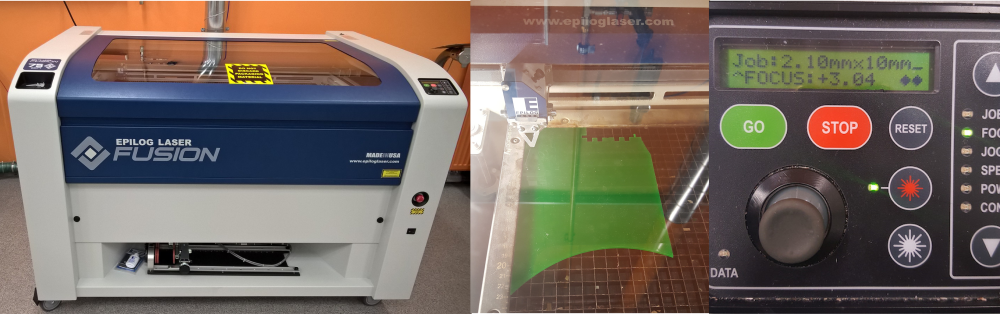
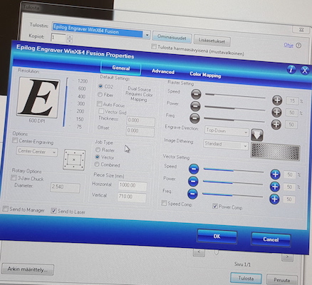
The three settings required for 'printing' documents with the laser cutter are speed, power and frequency for either raster or vector or combined types of file content. We used vector only, keeping power and frequency constant (100%), while changing speed to higher and lower percentage compared to the recommended (9%).
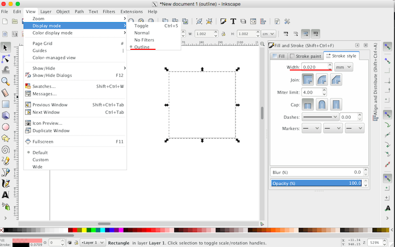
The test shape was a vector reproduction of the Malevich's Black Square scaled to 10 by 10 mm size; its outline was created in Inkscape (Stroke paint black, Stroke style 0.02mm). The file was converted to .pdf to be sent to the laser cutter.
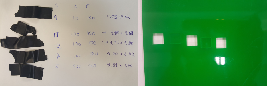
Due to the lack of the rigth color acryl, it was cut out on the green sheet. After the shape was cut out, we measured the sides of the Square. At the time of making measurements, the most precise tool we could find was the calibrator ruler so some of the measurement could be subject to errorTable below shows summaries of our findings.
| Speed | Power | Frequency | Square Measures (mm) |
|---|---|---|---|
| 5 | 100 | 100 | 9.81 x 9.79 |
| 7 | 100 | 100 | 9.80 x 9.82 |
| 9 | 100 | 100 | 9.80 x 9.82 |
| 11 | 100 | 100 | 9.89 x 9.84 |
| 12 | 100 | 100 | 9.90 x 9.84 |
| 13 | 100 | 100 | Not cut |
| 15 | 100 | 100 | Not cut |
 Testing in progress
Individual Assignments
Vinylcutting
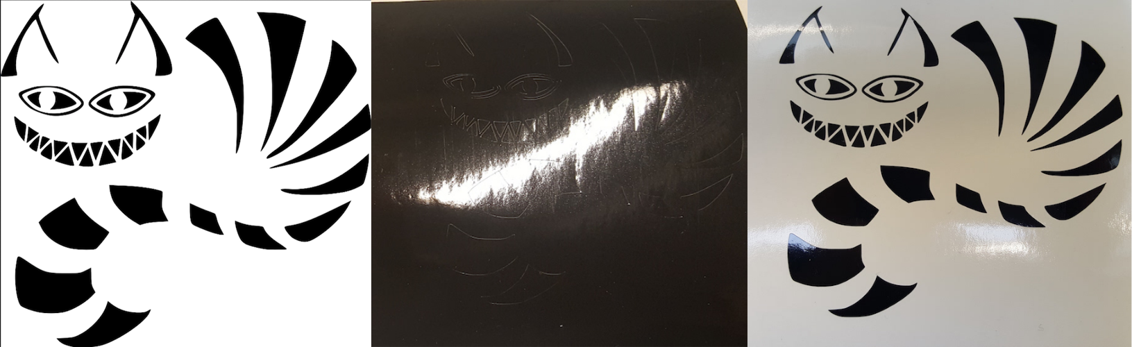
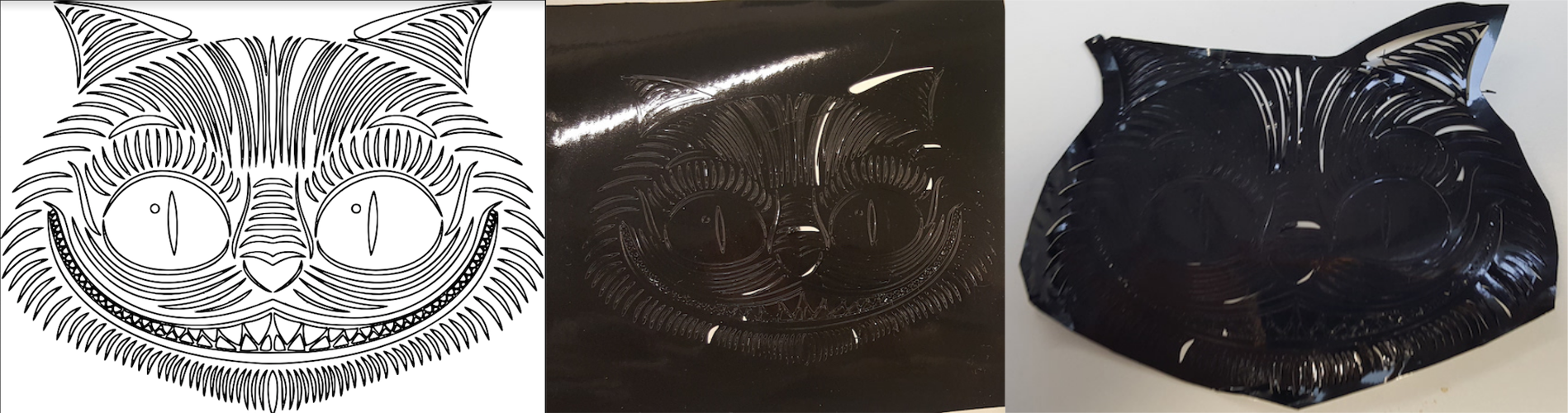
I chose two Cheshire cats found in Google images. The first one was the "safe" option meaning that there was no apparent reason for it not to come out right. As the second one had many more details to be cut out, I wasn't sure how clear they will come out.
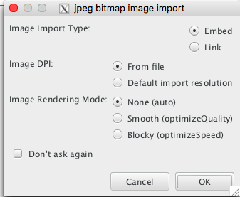
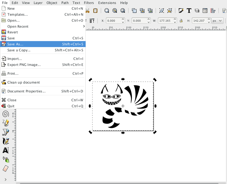
To prepare the cats for vinylcutting, I made some modifications to the files in Inkscape. I imported the images with the File - Import command.
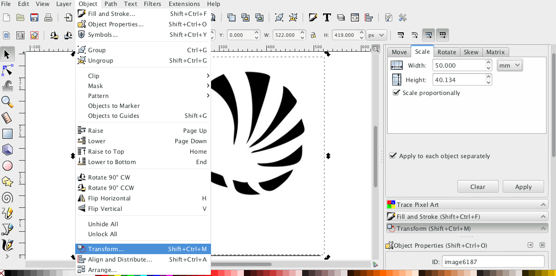
With the command Object - Transform I changed the size of the image
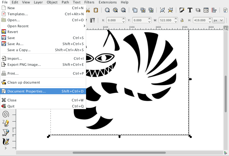
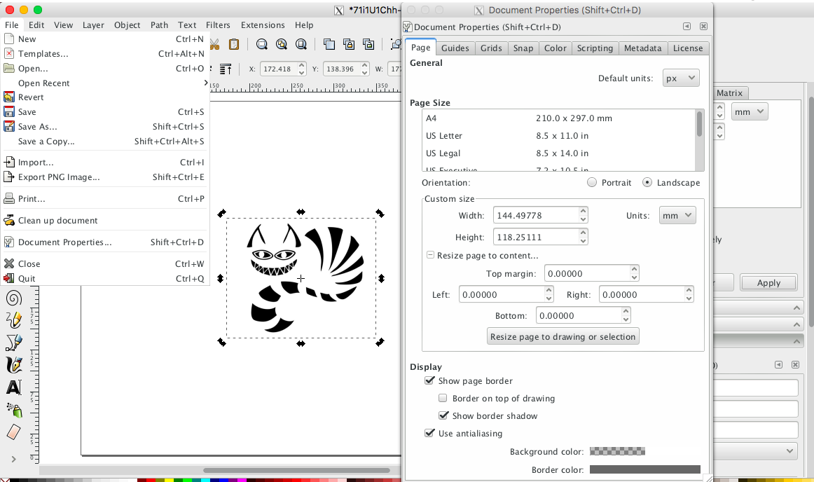
With the command I resized the document so that when I vinyl cut, the material is used as efficiently as possible.
Finally I saved the document as .png file for vinylcutting.
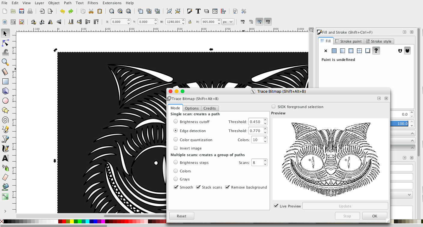
I repeated the same steps for the second cat. One extra step I made was inverting the image's color since originally the traces were white on black backgroud. Path - Trace Bitmap - Edge Detection was used to execut the trace.
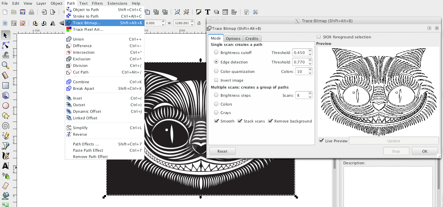
Since the trace is generated on top of the original image, I deleted the original one, and saved the document as a .png for vynil cutting

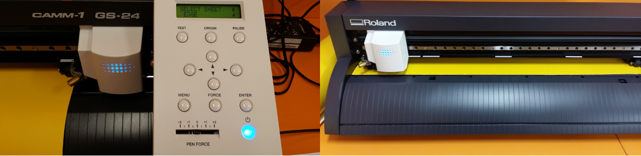
To start setting up the vinyl cutter, the vinyl sheet needs to be aligned with the edge and fix it with the lever. Then adjust the Edge with the arrows on the console and confirm with pressing Enter. Finally, the cut origin needs to be set with the arrows and confirmed until Origin Set appears.
To start vinyl cutting a file needs to be send to the Roland GS-24 and cutting area preferences are to be set. File - Print - Preferenes - Size - Cutting Area. Get from Machine option sets the width to correct value, and the length needs to be set to the value in Document Properties of the file to be printed.
Although not perfect, both cats ended up being cut out decently. Yet both will need trasfer film paper to make it over to the surface.
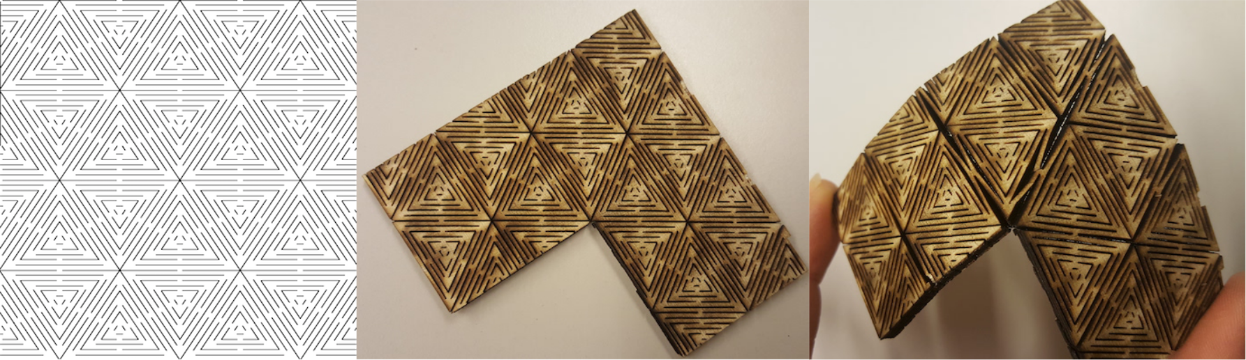
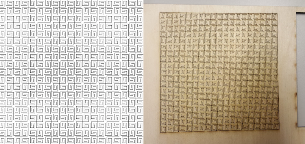
Flextures/Living hinges
Testing a few patterns I found online atObrary and Instructables
Parametric Press-Fit Construction Kit
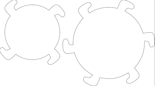
This one gets a well-deserved title 'challenge of the week'. Good chances to be a 'challenge of the month' too. To get the idea of what I want to achieve, I first sketched the shapes Inkscape. The plan was to have different-sized round pieces (with or without pattern) with the same-sized hooks. Attaching these in different ways would make various 3D shapes.
As I used Rhino for the last week's assignment, I continued with it this week too. In order to make parametric design, I had to use Grasshopper. Installing Grasshopper for Mac, requires getting another version (as opposed to the one I used last week) of Rhino, Rhino WIP.
Starting using Grasshopper was the point at which things went kind of sour. Or I should say the learning slope got too steep. I have not used Grasshopper before and I have found it to be not the most staightforward program. Although there seems to be nothing complex in my design, I was getting nowhere despite numerous efforts and searching for guidelines/tutorials that deal with a similar problem. Asked the crowd for help at Grasshopper's Discussions and a couple of kind people out there guided me to achieve this task. Many thanks to Hyungsoo Kim and Birk Binnard.
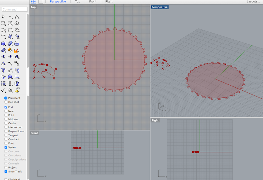
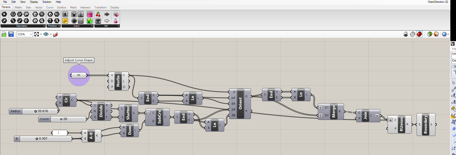
I ended up relying on the approach offered by Hyungsoo. In my opinion, this is a complex solution but is really handy for creating pieces I have been attepting to make. This solution requires drawing a hook, projected on a circle, by connecting points (vertices) coordinates of which can be changed should there be a need to modify the shape of the hook. The size of the curve is also possible to modify by changing input value. The radius of the circle and the number of hooks both have adjustable inputs too. Scaling of the circle and the hooks is independent. These adjustments allow changing the distance among the hooks to account for the kerf. This is how this solution looks like in Grasshopper and Rhino.
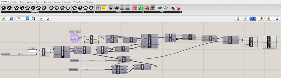
10 points (Pt) used as vertices (V) for Nurbs curve element to make up a hook. With the Gumball tool in Rhino these points can be adjusted to modify the shape of the hook.The end points of the curve are extracted (with End) and they are used to make a line segment (with Ln).
Circle element (Cir) with the defined radius is created.Divide element takes as an input the resulting circle shape (C) and divides it in to a predefined number of parts (N) to match the number of hooks. Shatter element takes as an input the circle shape (C) and parameter values to split at (t) from the Divide elements to create shattered remains (S).
A-B the mathematical subtraction calculates the length of the curve by subtractinng the adjustable value B from the set value A resulting into R. Construct domain (Dom) element takes as inputs user-defined value for determining the length of the curve and the R result from the A-B element. It results into a numeric domain (I) beween {A} and {B}.
Subcurve element takes as inputs the arc-like curves coming from the Shatter element (S) and the numeric domain (I) beween {A} and {B} coming from the Dom element. End points of the curves are extracted (End element) and the line is formed (Ln element). This Ln is used as a dB (direction) input in the Orient geometry component.
Orient geometry element takes as inputs a G (basic geometry, the hook), pA (reference point, start point of the line segment), dA (reference direction, the line between the points of the curve), pB (target point, the end of the arc-like subcurve coming from the circle), dB (direction, lines between the point of the subcurve coming from the circle). With these inputs the Orient element calcultes G, the reoriented geometry.
Data streams from the orient geometry are being merged (with Merge) and directed to the Join curve element. They are further forwarded to the RUnion element which unites all planar curves. Boundary element can be optionally used to creates one planar surface from the collection of the boundary edge curves.
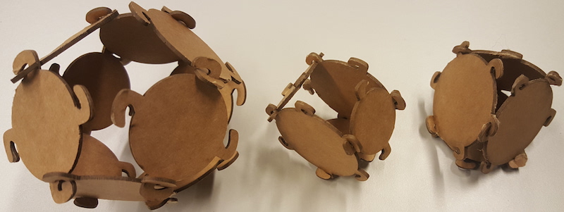
Using Grasshopper I created two circles: with 4 and 6 hooks, which I individually exported from Rhino to in Inkscape and made duplicates for cutting.
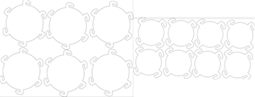
It took me several attempts to design and cut the pieces with the hooks of the right shape and size that could hold pieces together. Here are some assembled shapes.
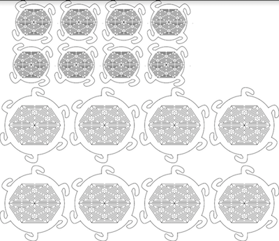
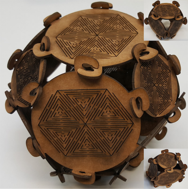
And finally, set of pieces with the flexible surface design.
Other fabrication design software for 3D/2D objects
I tested 123D Make and Flatfab both of which are handy for designing 3D object and easily exporting designs partitioned in 2D pieces for printing. Unfortunately, I did not find a way to use either to create the design I was looking for. So I just make a few random sketches in Flatfab and used a sample torus shape in 123D Make to get 2D layouts for it to be cut out. And yet to be assembled...
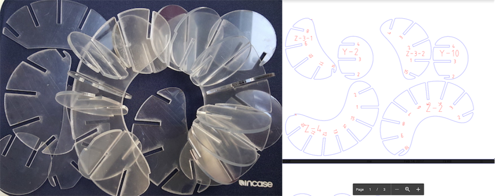
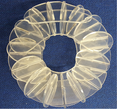
Update: Assembling accomplished. I ended up spending some more time than initially planned for putting together this shape because I lost the unsaved original 123DMake file due to the Windows OS update on my computer. I just had the .pdf file of the layout of the torus so I had to match the pieces only by using letters and numbers on the .pdf layout. I also did not mark acrylic pieces' codes on them right after laser cutting, so I had to be careful to make sure I identify them correctly when assembling. Next time, to make the assembly more efficient, I will pay more attention to save the 123DMake file and to mark the pieces right after they are lasercut.
Files:
Vinyl Cutter Designs, Grasshopper Parametric Design, Press Kit Components Design, Flexture design, 123D Make Torus Shape Layout .pdf