This week challenge is to create and program a board that measures something.
I've already work with input device on Output device week, so i start from it and the try to do something new.
Potentiometer
During the output device week I created a board that controlled a stepper motor and through a potentiometer defined the delay times between one step and the other.
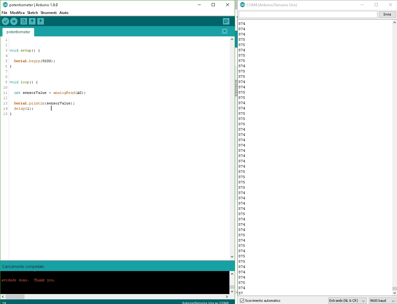
The Potentiometer is a three-terminal resistor with a sliding or rotating contact that change the voltage passage trought it.
.
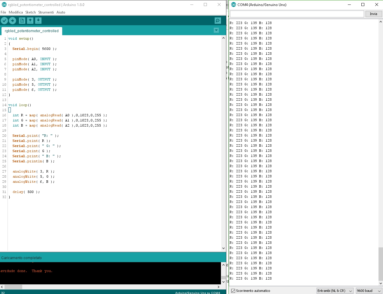
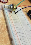
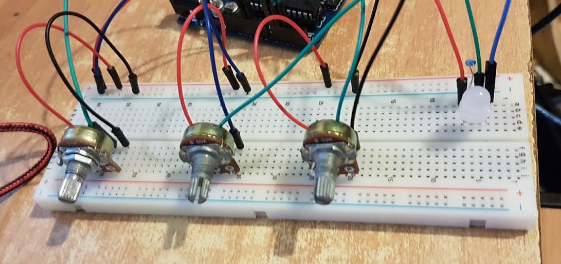
First of all I wrote a sketch to read the values of a potentiometer, than I made a scheme with three potentiometers to control the color of an RGB LED.
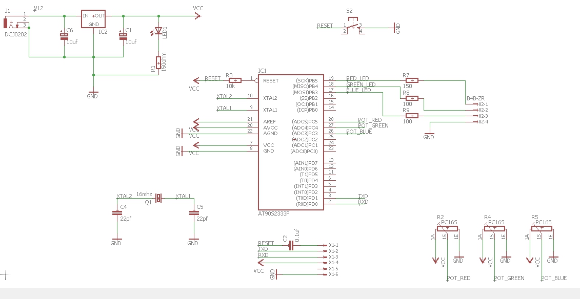
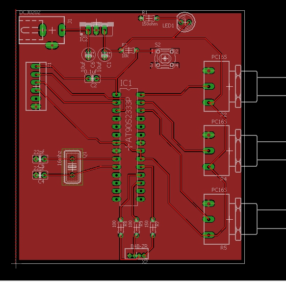
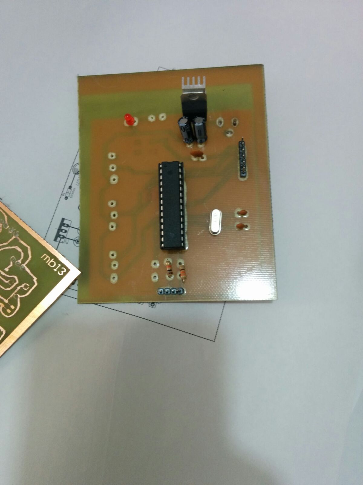
After finishing the tests with the breadboard I used Eagle to draw a board that did the same job.
Gyroscope
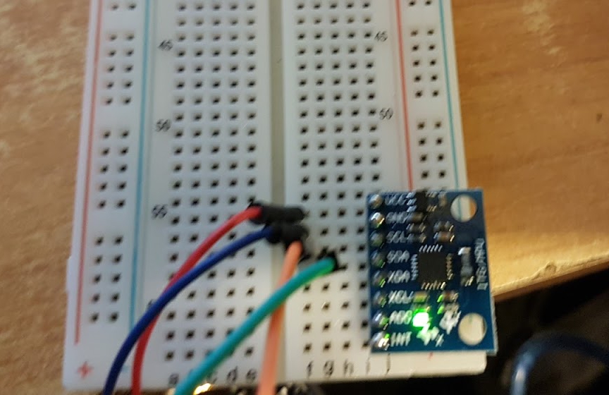
After work with potentiometers I connected a InvenSense MPU-6050 to a breadboard and read its values through a special sketch. The InvenSense MPU-6050 contains a 3-axis MEMS accelerometer and a 3-axis MEMS gyro in a single integrated. With the gyroscope we can measure the angular acceleration of a body on its own axis, while with the accelerometer we can measure the acceleration of a body in one direction. It is very accurate, as it has a 16 bit AD (from analog to digital) converter for each channel. So it captures the x, y and z channels simultaneously. The sensor has a standard I²C communication protocol, so it's easy to interface.
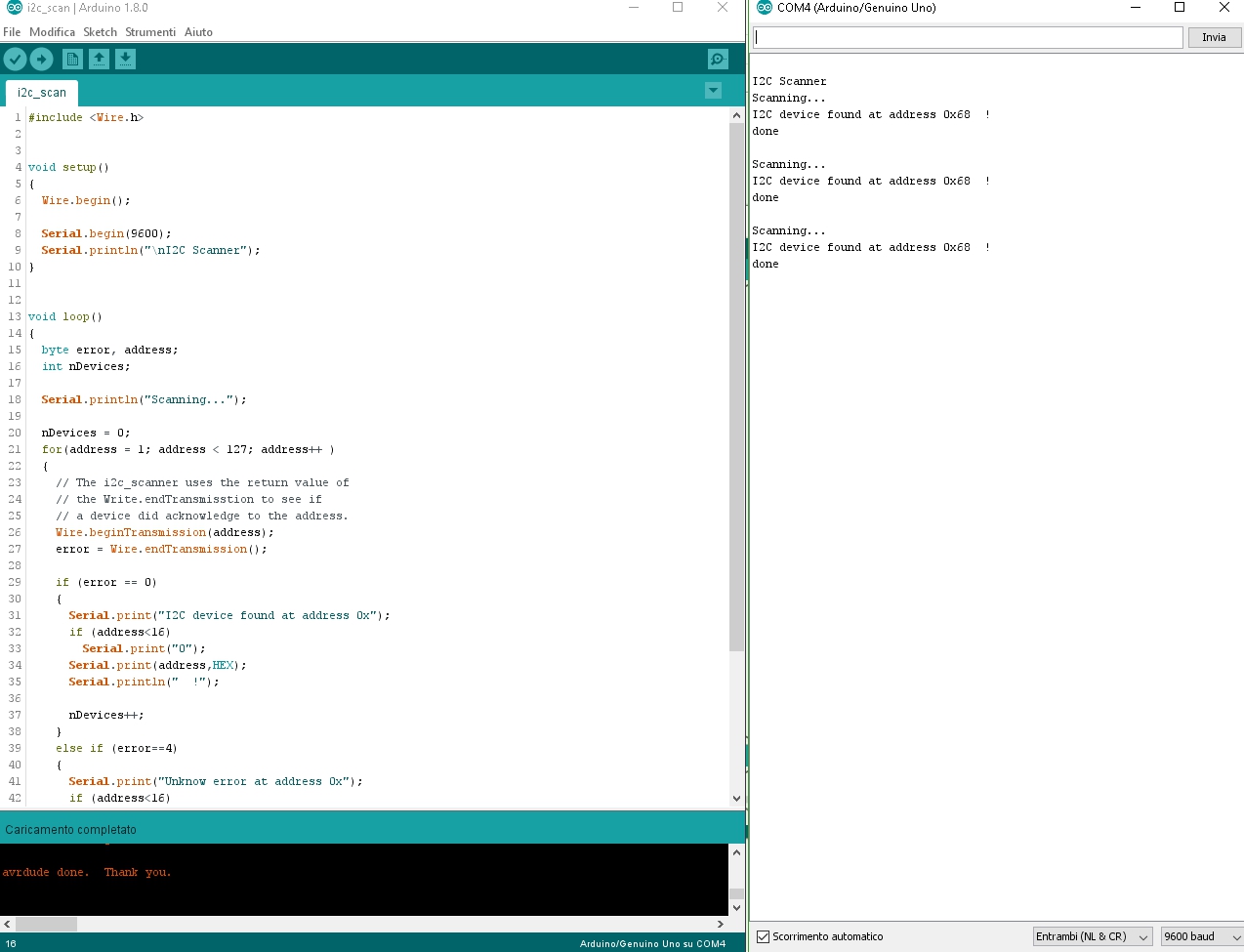
To operate the sensor we have to connect the SDA and SCL pins, and to check that all connections work properly we can use the i2c scan script.
If opening the serial monitor appears:
<<I2C device found at address 0x86>>.
the sensor is connected correctly, otherwise we did some error.
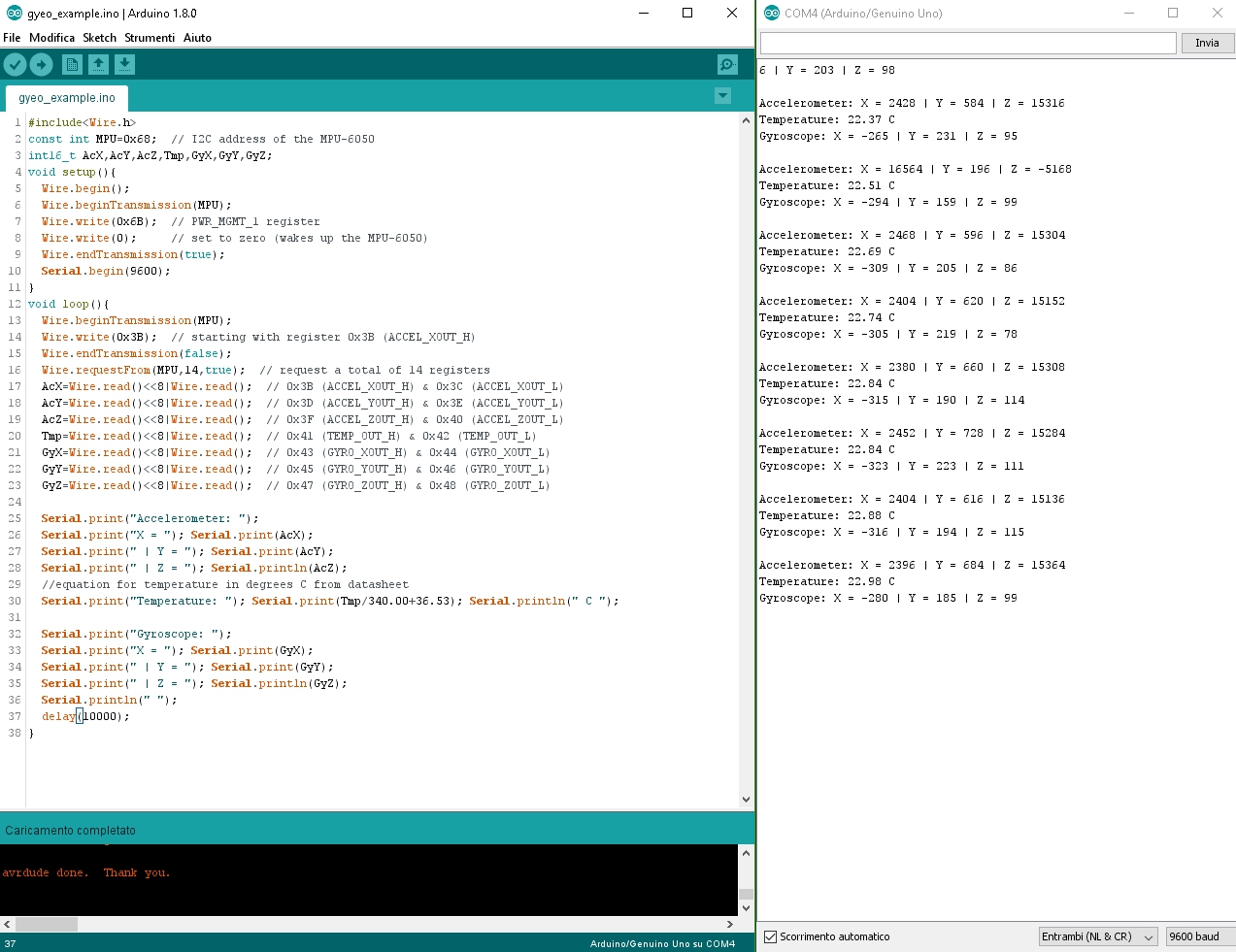
Once we are sure that the link works, there is nothing but uploading the script gyroscope that allows us to read the data changes received through the serial monitor.