This week we have to draw, milling, welding and program a circuit containing the output device
Design with Circuit.IO
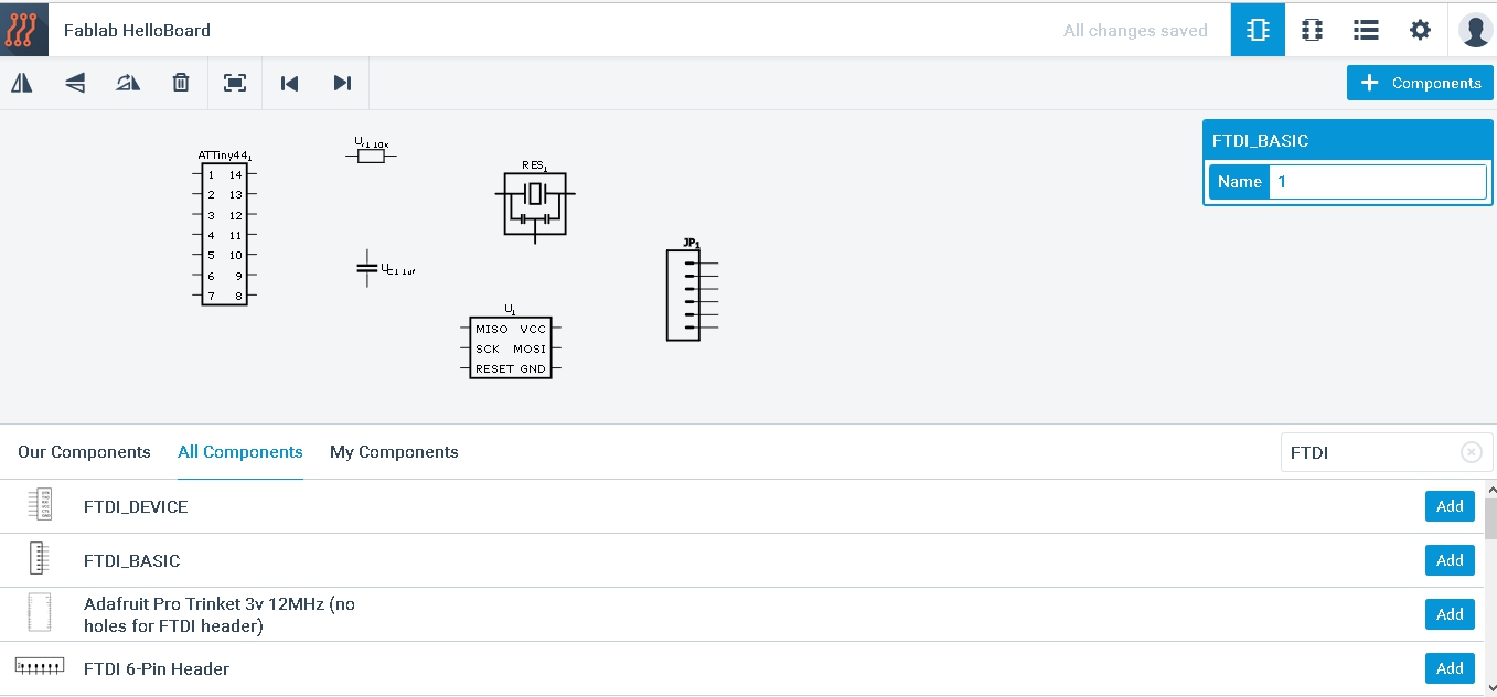
This week I wanted to test another program to draw electronic circuits and my choice fell on Circuit.io Autodesk.
Circuit.io is a software for the design of electrical patterns that run on a standard browser that allows you to:
- virtual design based on breadboard
- real time Arduino simulator
- editor of electronic components to add components to the shared library
- ability to incorporate their project, including simulation in a web page
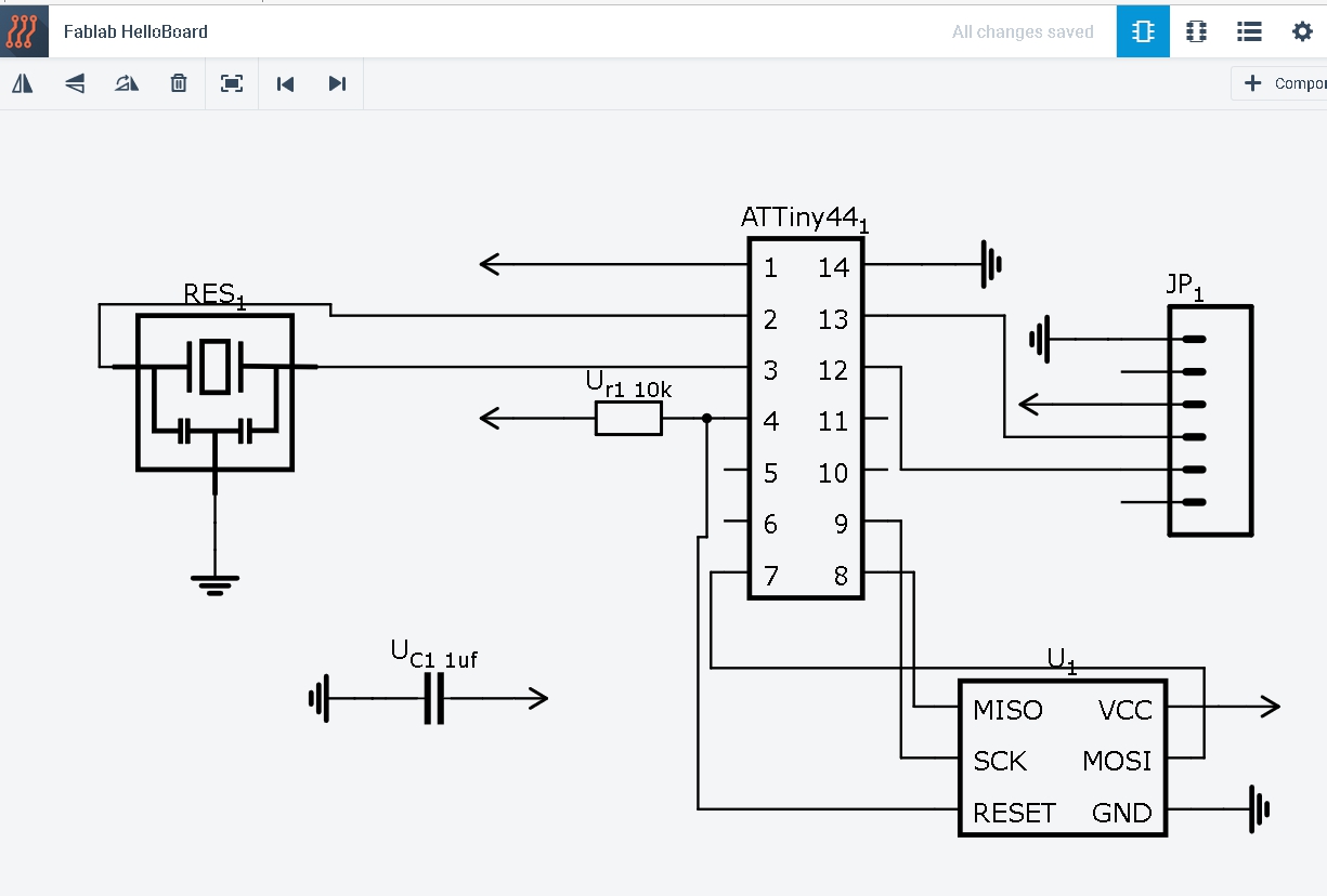
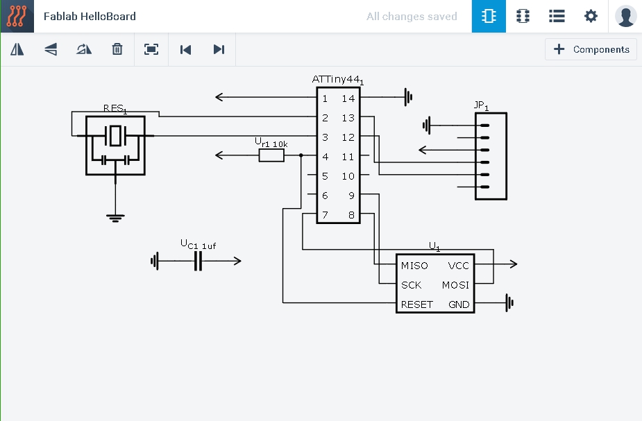
To understand with the instrument i've started redrawing the helloboard.
As with Eagle, look for the right component we need is always a bit complicated, but once you find everything you need I have completed the work fairly quickly.
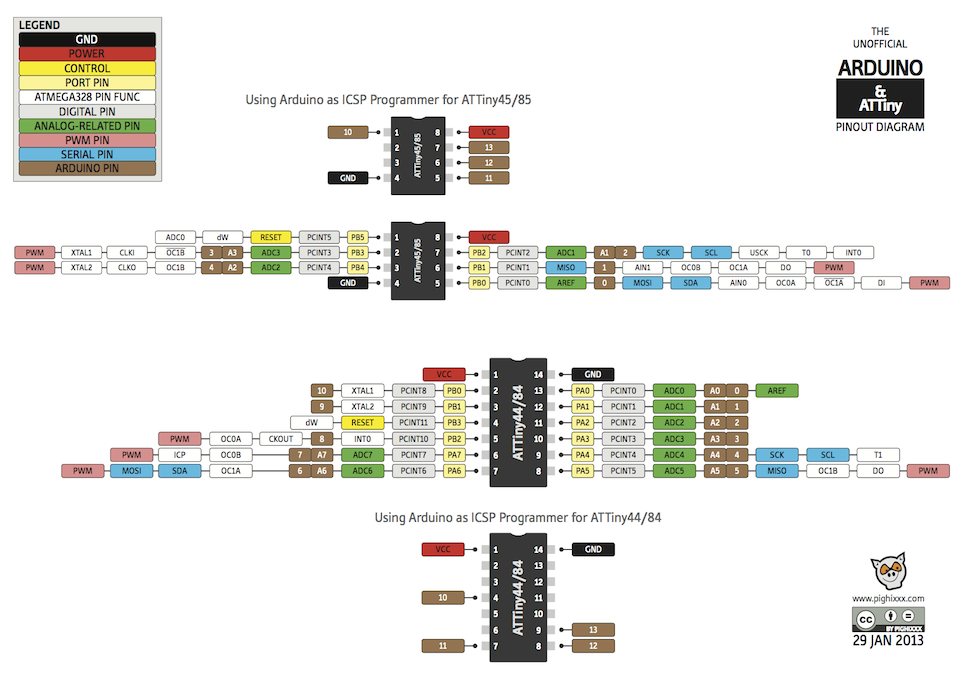
After finishing the helloboard I just have to add some input device and to do that I needed to know the pattern of the ATtiny pin.
I decided to add to the schema two input device (1 potentiometer and a slideswitch) and 2 output device (an LED and a stepper motor with driver) so as to be able to realize a tab to one 3d scanner.
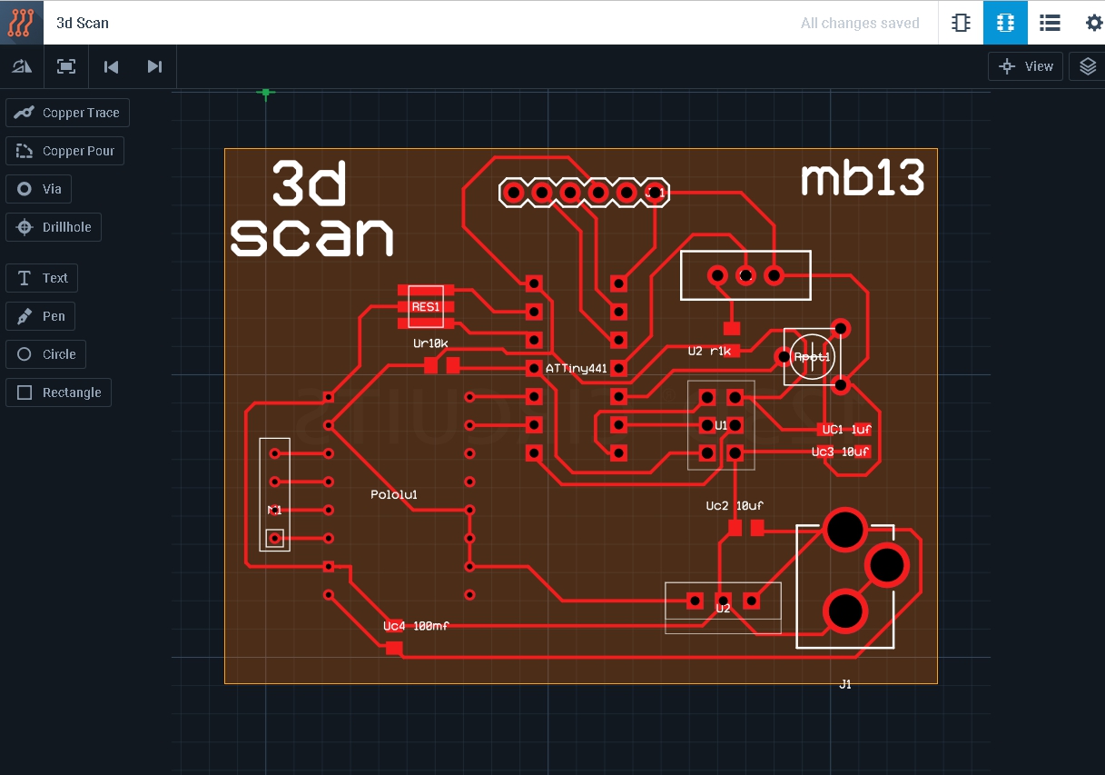
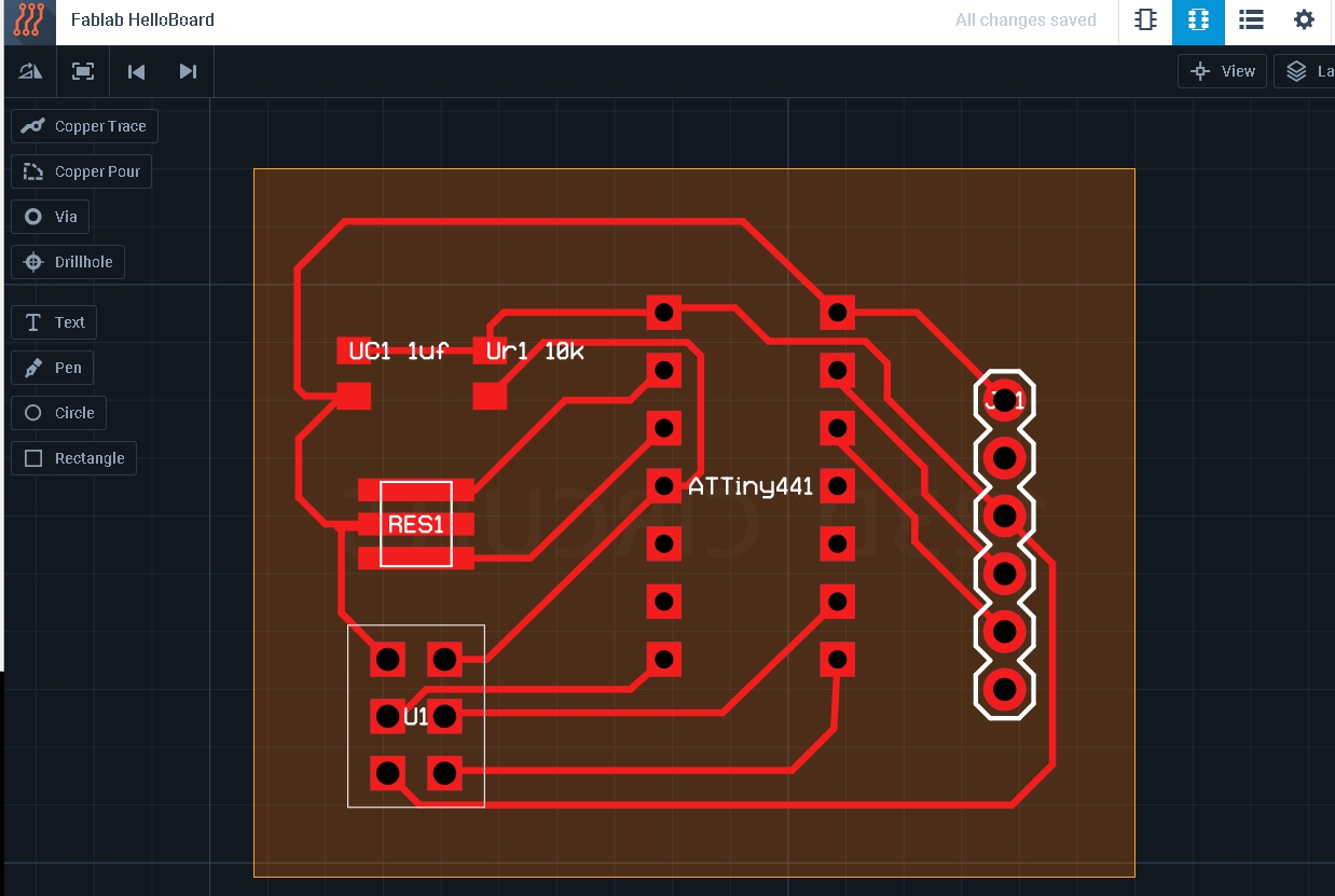
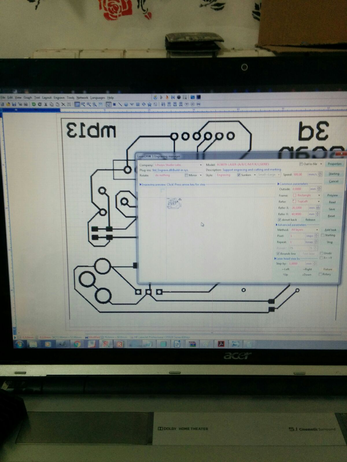
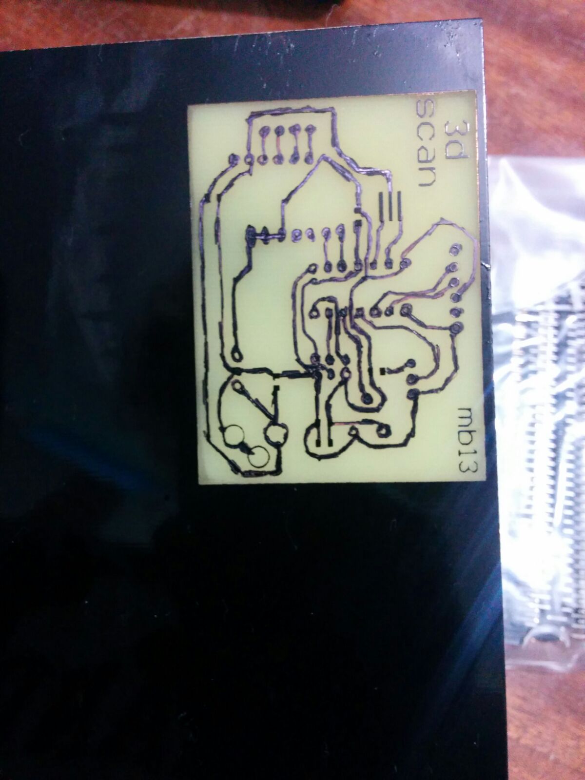
Laserucutting the pcb
We used a laser cut this week to make the PCB.
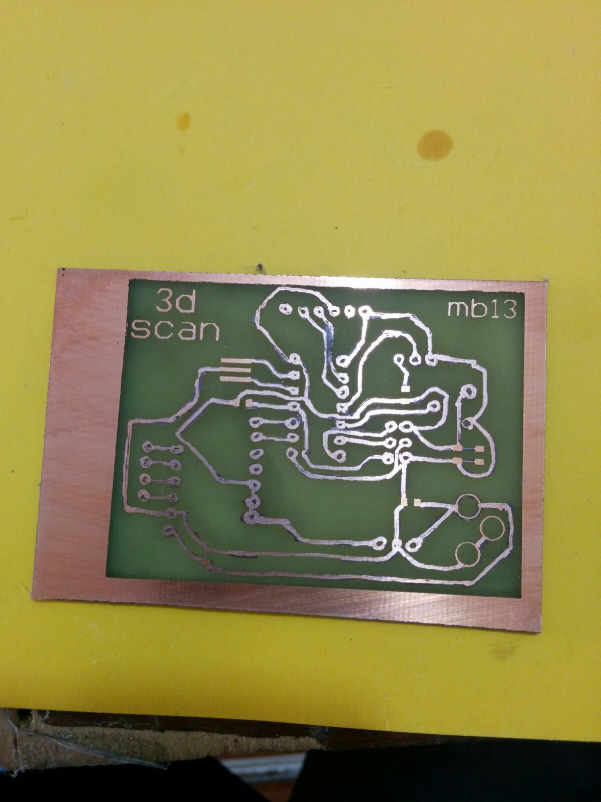
First, we colored the copper base in black, then exported the eagle files as pdf we started cutting them.
The work done we cleaned board and welded the components.
Programming
This time to programm the pcb i've wrote the script with arduino ide and loaded to the chip trought an arduino board.
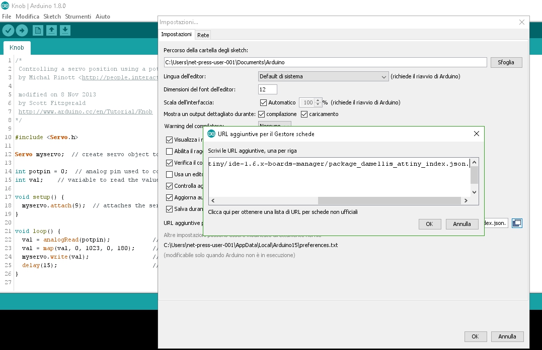
By default Arduino IDE doesn't support ATtiny85 so we should add ATtiny boards to Arduino IDE. Open File -> Preferences and in the Additional Boards Manager URLs give this url: https://raw.githubusercontent.com/damellis/attiny/ide-1.6.x-boards-manager/package_damellis_attiny_index.json.
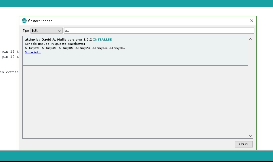
After this is done open Tools -> Board -> Board Manager.
After installing now you would be able to see a new entry in the Board menu
After opening Board Manager scroll down the list where it says "attiny by Davis A. Mellis". Click on that and install it.
Finish to set all i've connected the PCB to arduino using ISP pins:
- PIN11 to ATtiny's MOSI
- PIN12 to ATtiny's MISO
- PIN13 to ATtiny's SCK
- PIN10 to ATtiny's RESET
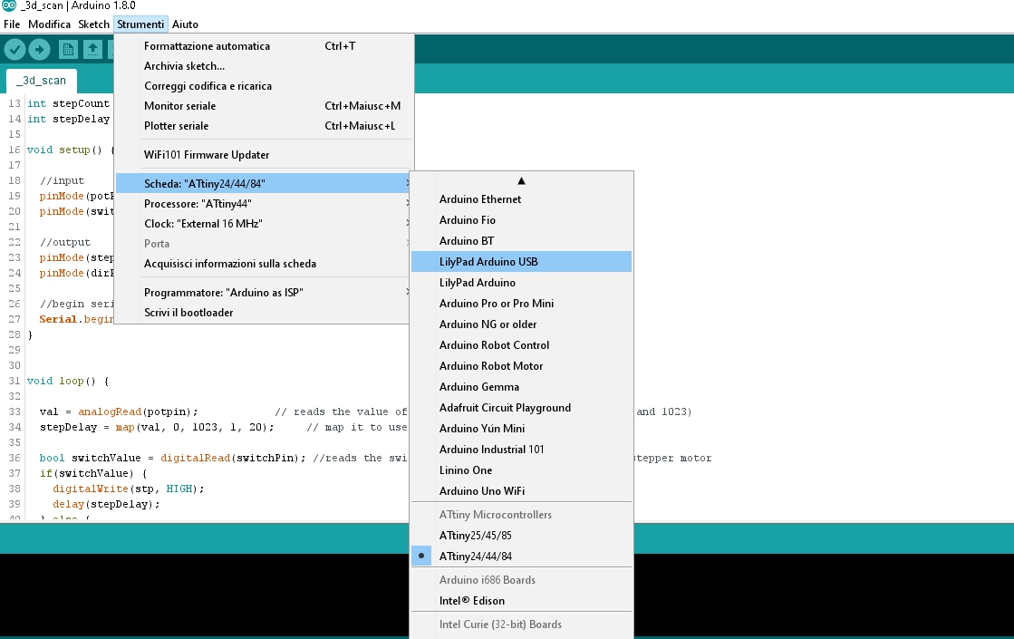
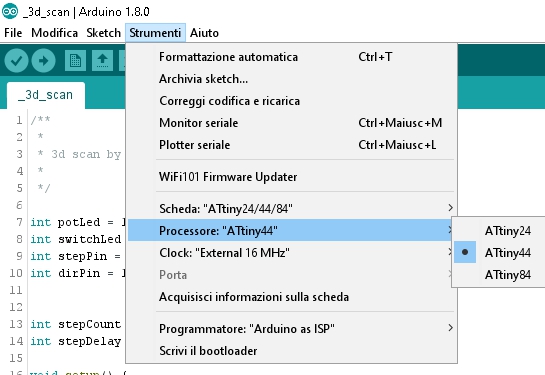
Remember to set the right processor type and clock before try to upload the sketch.