In this week I will be learning how to make PCB using milling machine.
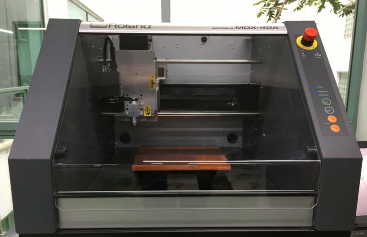
In our lab we are using Modela MDX-40A milling machine.
Generally electronic PCBs are first required to be designed using design softwares like Eagle, Orcad etc but for this week activity we will be directly downloading the layout file which we will be using for milling.
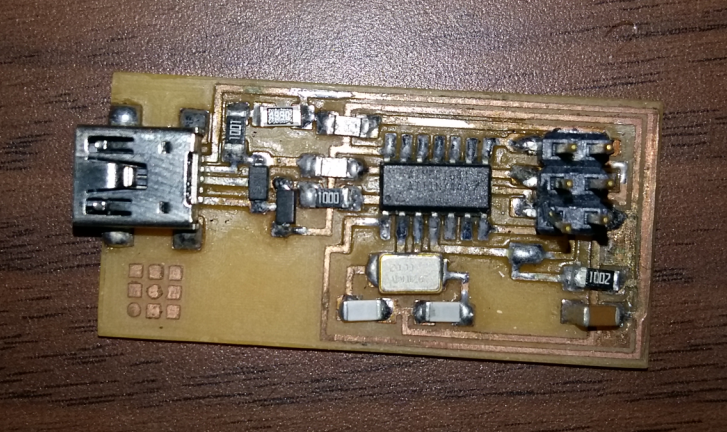
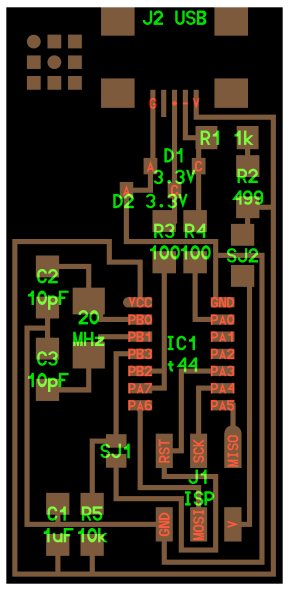
Below file will be used as reference while doing the soldering
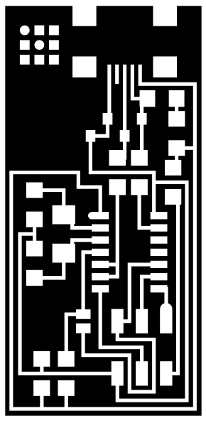
This file will be used for making layout. Its a monochrome file and back spot shows the places from were we have to remove the copper.
The third file is the outer boundary of the board using which we will be cutting the board.
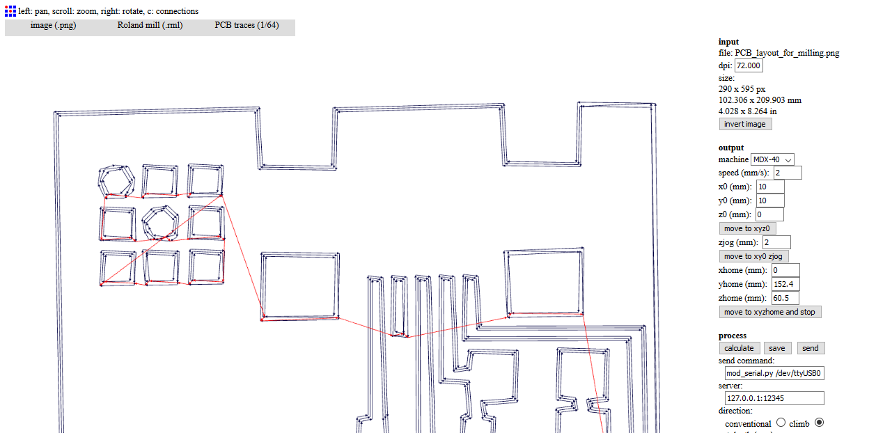
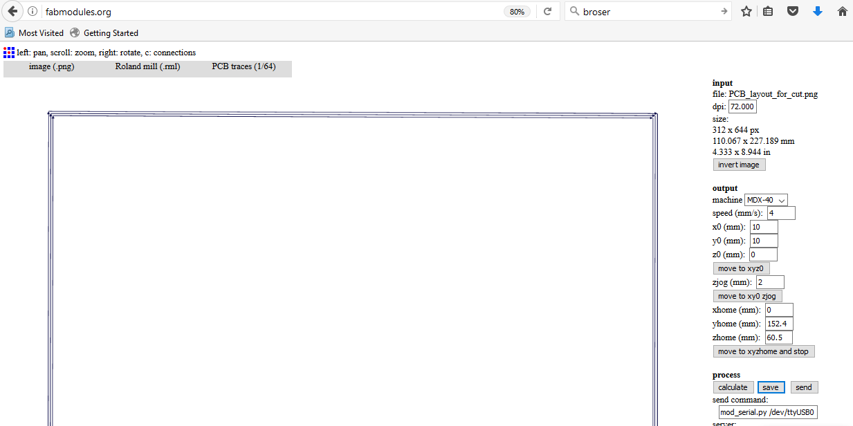
Generating milling .rml file using FAB module
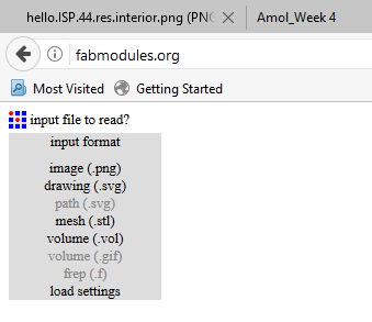
- Open FABmodule on browser. Select input format as .png
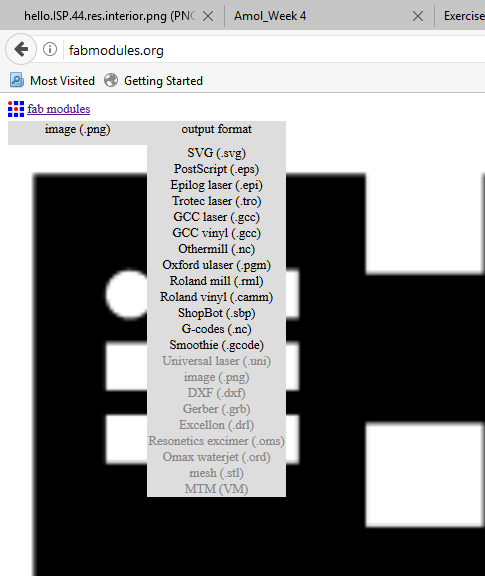
- As we are using Roland machine - select output format as .rml
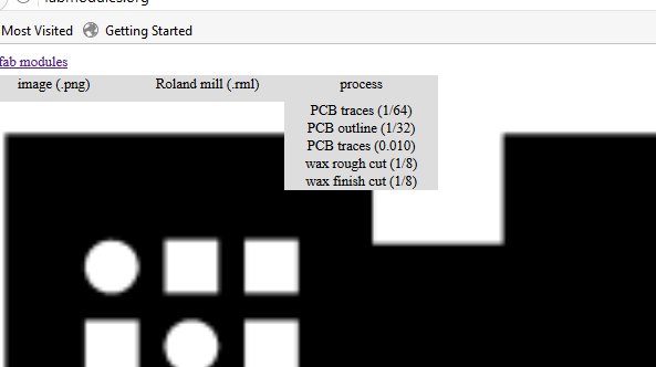
- In process select 1/64. It defines the traces value.
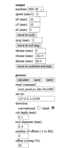
- Then default setting will get loaded. Select machine as MDX 40 and value which work for us were speed - 2mm/s, zjog - 2mm/s. Jog speed and cutting speed is kept same as to avoid jerks. Other important setting to modify is number of offset, I kept it 4(if its kept to -1 entire PCB will be milled increasing the milling time)
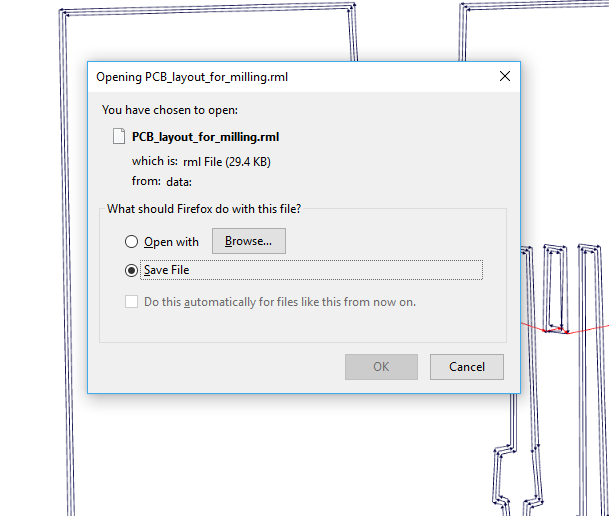
- Then click on save and select path were you wish to save the .rml file.
Milling the PCB
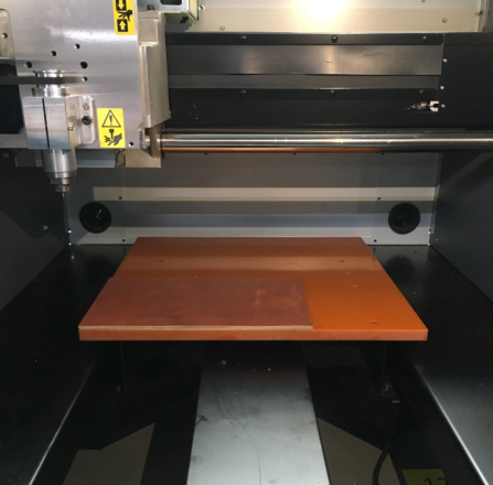
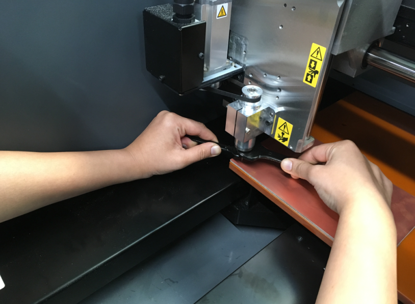
Fixing copper plate inside the milling machine. We can use masking tape to ensure the bare board doesn,t move.
Drill bit is inserted in collet and can be tighten using the spanner. I am using 1/64 inch drill bit.
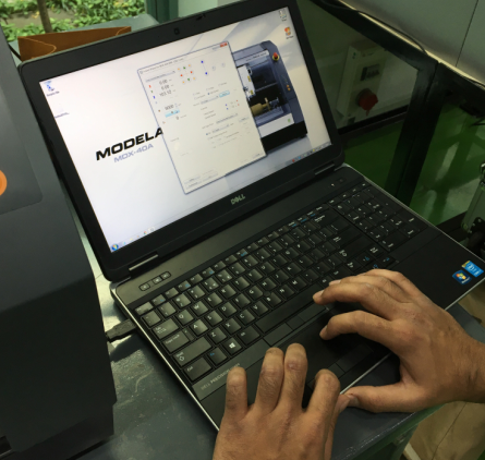
.rml file generated using fabmodule is given as input to Modella machine software
Next step is to set the origin
Using the software GUI we can move the milling bit to select the x0,y0 and z0.
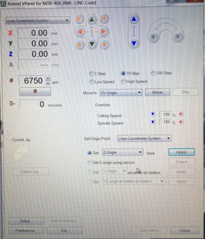
Extra causion is to be taken while setting the z0 as it may break the drill. Reduce the step to 1 step or 10 step when the drill bit is near to the board. Another way which I tried was get the bit as close to board as possible without touching the board and then loosen it allowing it to touch the board and then tighten it at this position.
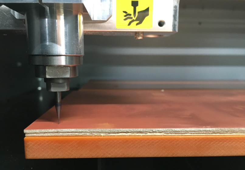
Next task is to start the milling process and observe if every thing is going okay.
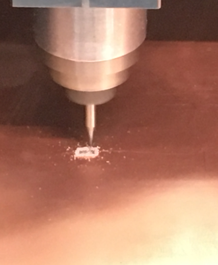
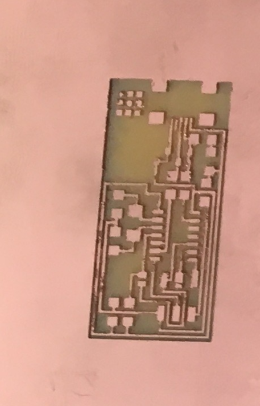
Once miling is done it can removed and track continuity can be checked using multimeter.
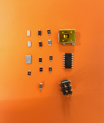
Next task is to solder the components on the board. Before starting get everything ready.
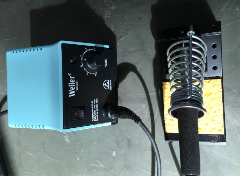
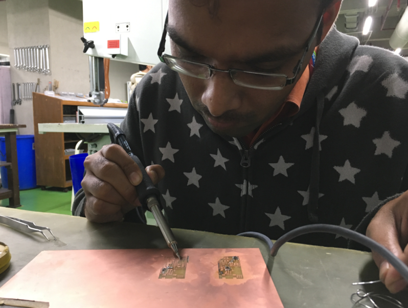
My solder station
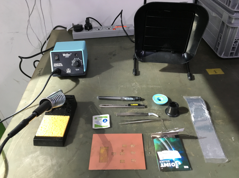
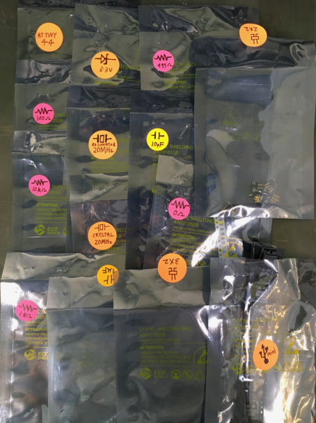
Getting all components required to be stuff on the board ready
I tried my hands over soldering as I was doing after a long time.
We can also use the milling machine to cut the PCB into proper size.
For same using the interior png file to create .rml file
After properly miling and cutting the PCB final task is to solder it.