Studying RTC - bq32000 and interfacing it with microcontroller over I2C.
As in my project I intended to track the uses of the machine by an individual it was required to use an accurate rtc
So have decided to use bq 32000 real time clock from TI
Main features of RTC are listed below:
Below is the datasheet of BQ 32000 RTC
BQ 32000 datasheetI2C interface with microcontroller
The I2C interface allows control and monitoring of the RTC by a microcontroller. I2C is a two-wire serial interface. The bus consists of a data line (SDA) and a clock line (SCL) with off-chip pullup resistors. When the bus is idle both SDA and SCL lines are pulled high.

A master device, usually a microcontroller or a digital signal processor, controls the bus. The master is responsible for generating the SCL signal and device addresses. The master also generates specific conditions that indicate the START and STOP of data transfer. A slave device receives and/or transmits data on the bus under control of the master device. BQ32000 operates only as a slave device.
I2C communication is initiated by a master sending a start condition, a high-to-low transition on the SDA I/O while SCL is held high. After the start condition, the device address byte is sent, most-significant bit (MSB) first, including the data direction bit (R/W). After receiving a valid address byte, this device responds with an acknowledge, a low on the SDA I/O during the high of the acknowledge-related clock pulse. This device responds to the I2C slave address 11010000b for write commands and slave address 11010001b for read commands.
Further details are available in data sheet
Making Eagle schematic for RTC reading its datasheet.
We have to connect 3 pins of RTC to the microcontroller pin5(SDA), pin6(SCL) and pin7(INT). All these pins are pulled up using 4.7K resistor. As we want the RTC to function when power is down we have to use a backup power source. Here we can either use super capacitor or 3.3V battery. As supercap are expensive and I was not having any size limitation I decided to use 3.3V coin battery. Now selected a verticle holder for battery.
Acquracy of RTC depends on the acquracy of crystal. RTC requires a exact crystal of value 32.768 KHz.We have ensure that the crystal is located as close as possible to OSCI and OSCO pin i.e pin 1 and 2 of RTC.

Another point was there should be an option for setting the time of the RTC when it is turned On for the first time. For this I decided to use serial interface. I am using MAX RS232 IC for same.
Eagle circuit for same as below
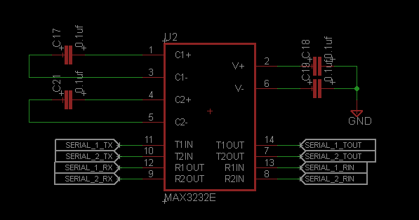
MAX232 IC support 2 RS 232 ports. I will be one for communication with reader and another for PC.
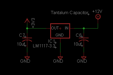
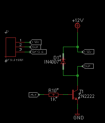
In addition to this I am LM 1117 3.3V regulator from TI and a circuitary for dring SSR which is similar to one use in output device.
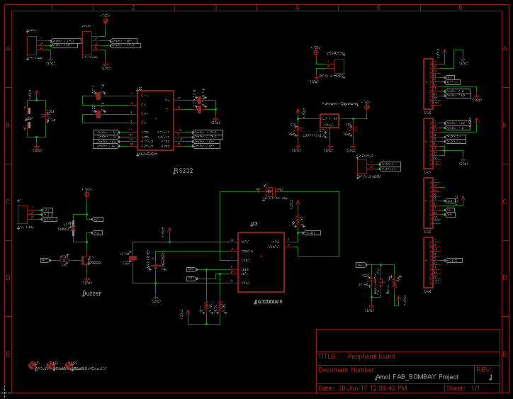
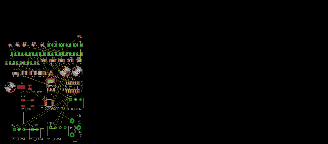
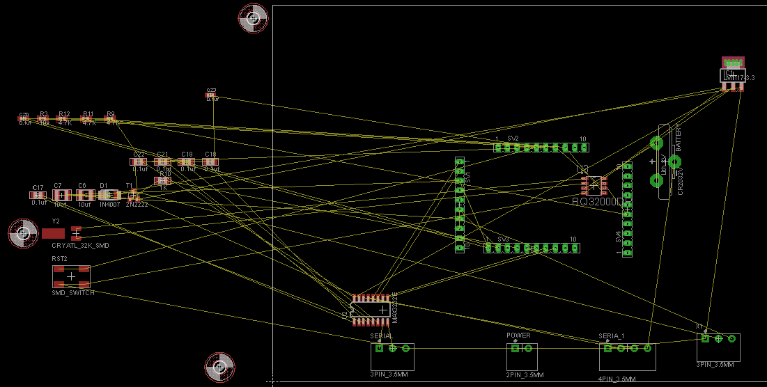
So final circuit diagram look like below
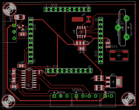
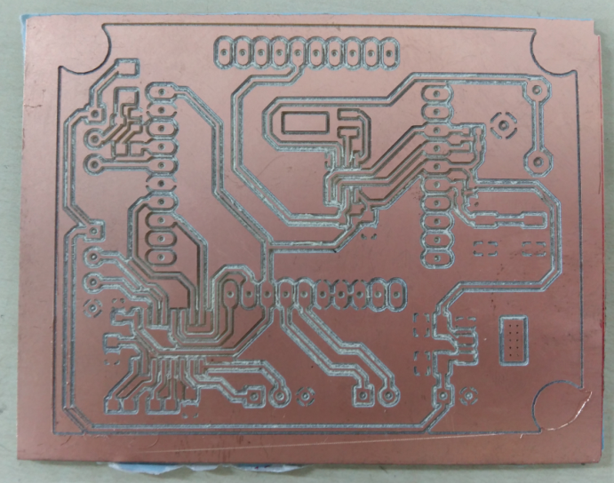
Layout for PCB was prepared using Eagle
I faced problem in milling this PCB as I had kept track width and clearance of 0.2 mm. I tired to mill using 0.1mm drill but it was in vain.
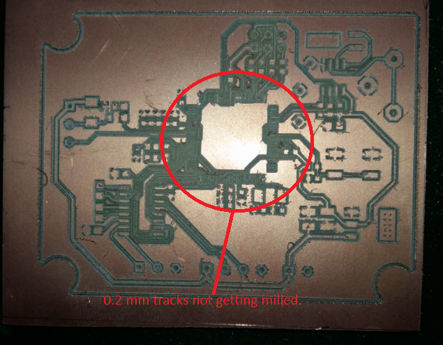
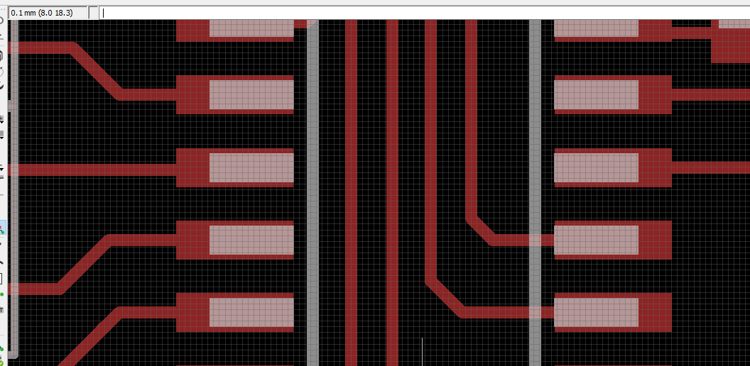
So I increased the track width to 0.5 is relayouted the PCB.
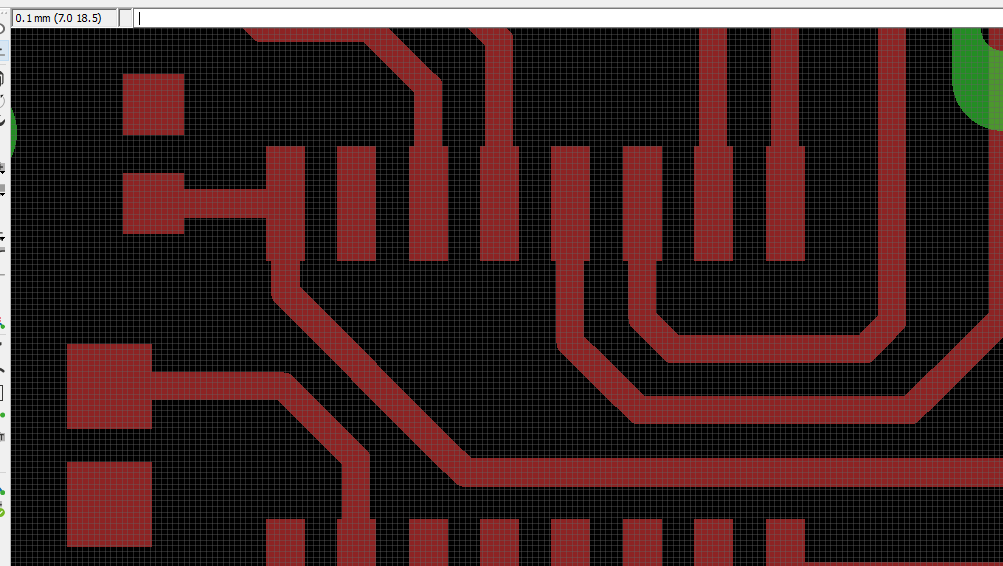
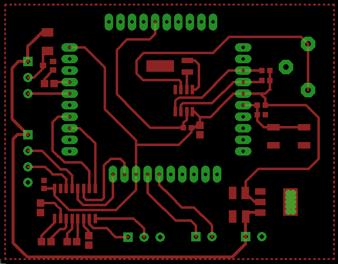
Adding ground polygon
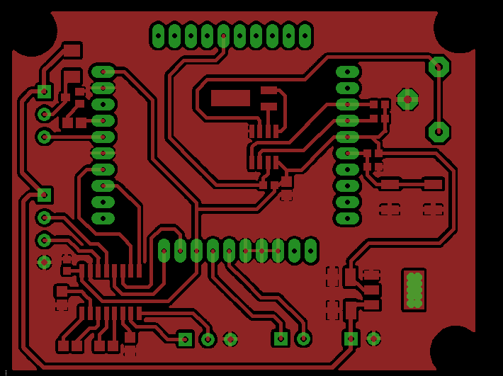
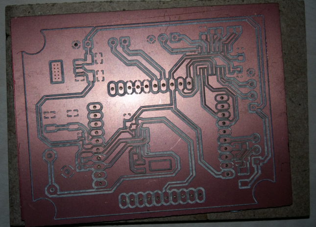
I got the PCB milled and soldered it.
- Milled PCB
- Holes drilled for through hole components
- Stuffing ICs and other components
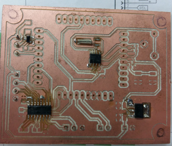
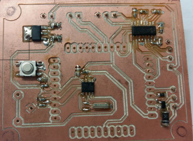
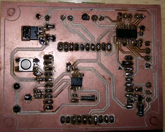
I Have used MVC connector of 3.5mm pitch as they provide connection ease and it was required in my project. Also on header controller PCB will be mounted
So I2C slave PCB was ready.
Now I2C master PCB was to be designed and fabricated. I had planned to LM 3S 6965 TI stellaris microcontroller in my final project. So this week I utilized to finished my I2C communication part with RTC.
I2C Master PCB
As it was not possible to mill the microcontroller board as its pitch was 0.2mm. So decided to make it on layer board.
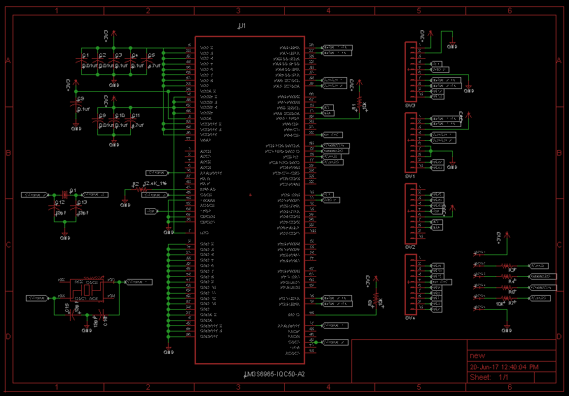
This circuit included the microcontroller, crystal and Debug connector.
Below is the final circuit diagram of microcontroller.
Making PCB layout
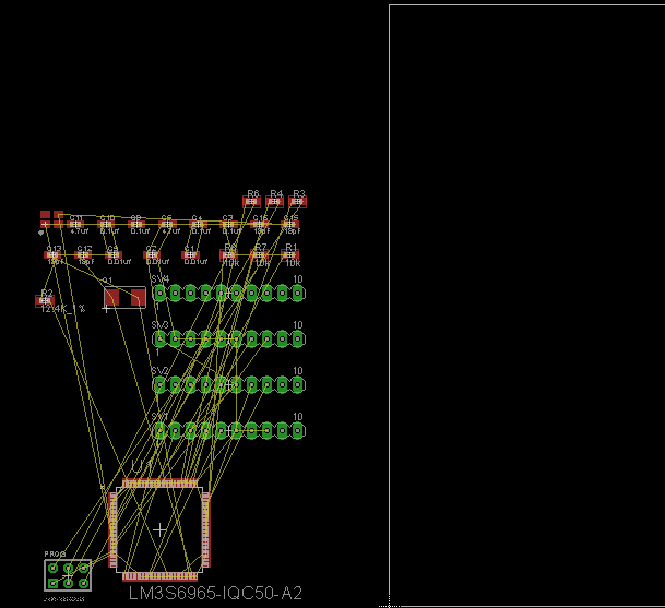
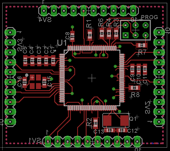
Being a 2 layer board I have kept below layer as ground so whereever I required to provide ground connection I directly put an via.
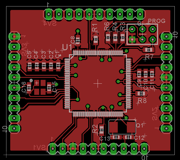
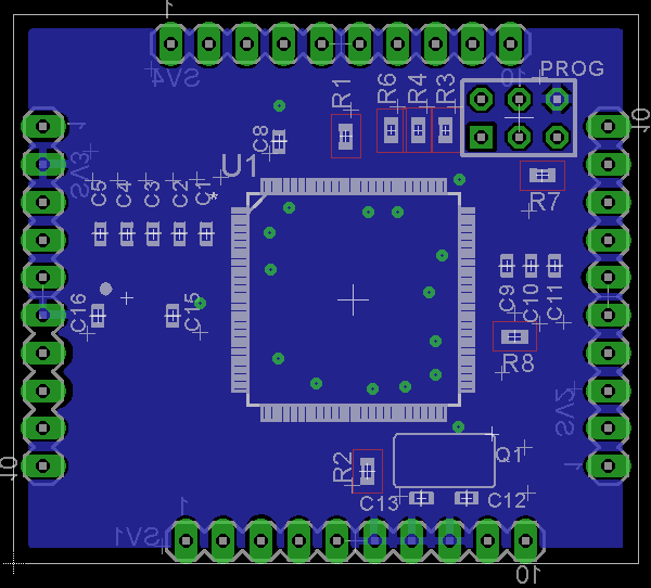

I felt layouting is easier on 2 layer PCB as compared to single layer.
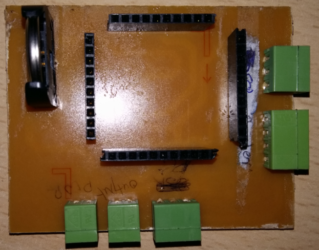
This PCB was stuffed and connected to Peripheral PCB using headers stuffed on both the PCBs.
Firmware for I2C communication
- Initializing controller I2C and setting it as master.
- Defining a structure to date and time values
- #defines for RTC
- Writing Driver functions for reading data from rtc
- Writing driver function for writing data into RTC.
- Writing application level function which will read date time from RTC and return it
- Writing apllication level function for setting RTC Date time
    void I2C0_init()
{
	GPIOPinTypeGPIOOutput( GPIO_PORTB_BASE, (I2C0SCL| I2C0SDA) );
	mili_sec(50);
	SysCtlPeripheralEnable(SYSCTL_PERIPH_I2C0);
	GPIOPinConfigure(GPIO_PB2_I2C0SCL);
	GPIOPinConfigure(GPIO_PB3_I2C0SDA);
	GPIOPinTypeI2C(GPIO_PORTB_BASE, GPIO_PIN_3 | GPIO_PIN_2);
	I2CMasterInitExpClk(I2C0_MASTER_BASE, SysCtlClockGet(), false);
}
typedef struct
{
	unsigned char date;
	unsigned char month;
	unsigned char year;
	unsigned char hour;
	unsigned char min;
	unsigned char sec;
	unsigned char bufferdate[8];
	unsigned char buffertime[8];
}date_time;
#define RTC_ADDR 		0x68
#define SECOND 			0x00
#define MINUTE 			0x01
#define HOUR 			0x02
#define DAY 			0x03
#define DATE 			0x04
#define MONTH 			0x05
#define YEAR 			0x06
unsigned char rtc_Read(unsigned char slave_addr, unsigned char Reg)
{
	int i;
	i2c_timeout_counter = 0;
	I2CMasterSlaveAddrSet(I2C0_MASTER_BASE,slave_addr , false);
	I2CMasterDataPut(I2C0_MASTER_BASE, Reg);
    I2CMasterControl(I2C0_MASTER_BASE, I2C_MASTER_CMD_SINGLE_SEND);
    while(I2CMasterBusy(I2C0_MASTER_BASE) && (i2c_timeout_counter < 2));
	if(i2c_timeout_counter >= 2)
	{
		I2C0_init();
		for(i = 0; i<3; i++)
		{
			long_beep(500,2);
		}
	}
	i2c_timeout_counter = 0;
	I2CMasterSlaveAddrSet(I2C0_MASTER_BASE, slave_addr , true);
    I2CMasterControl(I2C0_MASTER_BASE, I2C_MASTER_CMD_SINGLE_RECEIVE);
 	while(I2CMasterBusy(I2C0_MASTER_BASE) && (i2c_timeout_counter < 2));
	if(i2c_timeout_counter >= 2)
	{
		I2C0_init();
		for(i = 0; i<3; i++)
		{
			long_beep(500,2);
		}
	}
	return(I2CMasterDataGet(I2C0_MASTER_BASE));
}
void rtc_Write(unsigned char slave_addr, unsigned char Reg, unsigned char value )
{
	int i;
	i2c_timeout_counter = 0;
	I2CMasterSlaveAddrSet(I2C0_MASTER_BASE, slave_addr , false);
	I2CMasterDataPut(I2C0_MASTER_BASE, Reg);
    I2CMasterControl(I2C0_MASTER_BASE, I2C_MASTER_CMD_BURST_SEND_START);
    while(I2CMasterBusy(I2C0_MASTER_BASE) && (i2c_timeout_counter < 2));
	if(i2c_timeout_counter >= 2)
	{
		I2C0_init();
		for(i = 0; i<3; i++)
		{
			long_beep(500,2);
		}
	}
	i2c_timeout_counter = 0;
	I2CMasterDataPut(I2C0_MASTER_BASE, value);
    I2CMasterControl(I2C0_MASTER_BASE, I2C_MASTER_CMD_BURST_SEND_FINISH);
    while(I2CMasterBusy(I2C0_MASTER_BASE) && (i2c_timeout_counter < 2));
	if(i2c_timeout_counter >= 2)
	{
		I2C0_init();
		for(i = 0; i<3; i++)
		{
			long_beep(500,2);
		}
	}
}
date_time* get_Current_Date_Time()
{
//	int i=0;
	current_time.sec    = bcd_to_hex(rtc_Read(RTC_ADDR, SECOND ) & 0x7F);
	current_time.min    = bcd_to_hex(rtc_Read(RTC_ADDR, MINUTE ) & 0x7F);
	current_time.hour   = bcd_to_hex(rtc_Read(RTC_ADDR, HOUR   ) & 0x3F);
	current_time.date   = bcd_to_hex(rtc_Read(RTC_ADDR, DATE   ) & 0x3F);
	current_time.month  = bcd_to_hex(rtc_Read(RTC_ADDR, MONTH  ) & 0x1F);
	current_time.year   = bcd_to_hex(rtc_Read(RTC_ADDR, YEAR   ) & 0xFF);
	current_day 		= bcd_to_hex(rtc_Read(RTC_ADDR, DAY    ) & 0x07);

	if(	(current_time.year<=100) && (current_time.date>=1)  &&
		(current_time.date<=31)  && (current_time.month>=1)	&&
		(current_time.month<=12) && (current_time.hour<=23) &&
		(current_time.min<=59) 	 && (current_time.sec<=59)	   )
	{
		return ¤t_time;
	}
	else
	{
		I2C0_init();
		return 0;
	}
}
long set_Current_Date_Time(date_time* new_Date_Time )
{
	if(validate_datetime(new_Date_Time))
	{
		if((new_Date_Time->year != date_time_variable.year) || (new_Date_Time->month != date_time_variable.month) ||(new_Date_Time->date != date_time_variable.date) ||(new_Date_Time->hour != date_time_variable.hour) ||(new_Date_Time->min != date_time_variable.min) )
		{
			rtc_Write (RTC_ADDR , SECOND , hex_to_bcd(new_Date_Time->sec)    );
			rtc_Write (RTC_ADDR , MINUTE , hex_to_bcd(new_Date_Time->min)    );
			rtc_Write (RTC_ADDR , HOUR   , hex_to_bcd(new_Date_Time->hour)   );
			rtc_Write (RTC_ADDR , DATE   , hex_to_bcd(new_Date_Time->date) 	 );
			rtc_Write (RTC_ADDR , MONTH  , hex_to_bcd(new_Date_Time->month)  );
			rtc_Write (RTC_ADDR , YEAR   , hex_to_bcd(new_Date_Time->year)	 );
		}
		return(0);
	}
	return(-1);
}
Have written driver files for RTC bq32000 which can be used if any one wish to use this RTC in future.
The files can be downloaded from the link provided at the end of this page.
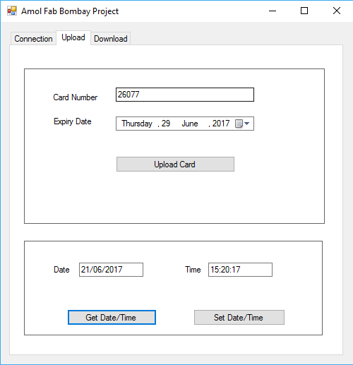
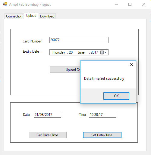
For testing the I2C code have define Date time set and read function in software which can read and set the date time.
Commands for setting and reading date and time
Command : "SD+DDMMYYYYhhmmss"
Reply : "SDOK" if okay and "SDERR" in case of error
Command : "GD"
Reply : "GD+DDMMYYhhmmss"
Same was verified on software GUI. Further details about software are included in next week assignment.
Interconnecting 2 board
There are 2 boards which will be communicating over I2C: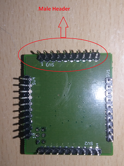
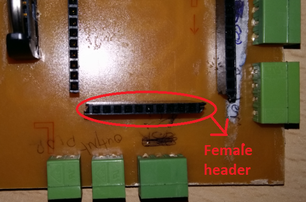
Controller board is placed on top of Peripheral board.