In my final project I have to drive lab machines like 3D printed, milling machine etc so I had decided to use SSR(Solid State Relay)as an switch to turn ON and OFF the machines.
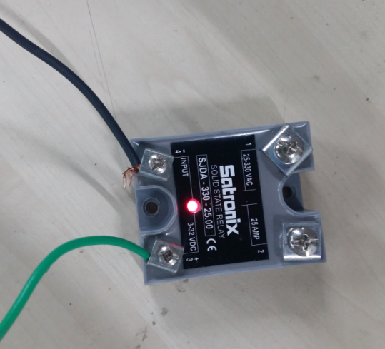
As the current requirement of these machine is high, I have selected an SSR with 25A current rating. I have selected an Satronix SSR.
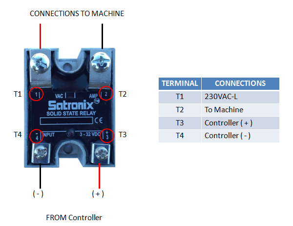
SSR has 4 terminal - To turn SSR ON we have provide +ve DC voltage and connect the output terminal of SSR in series of AC supply.
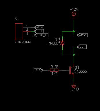
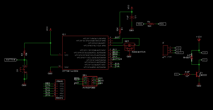
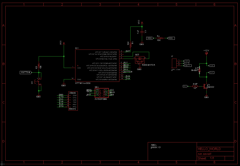
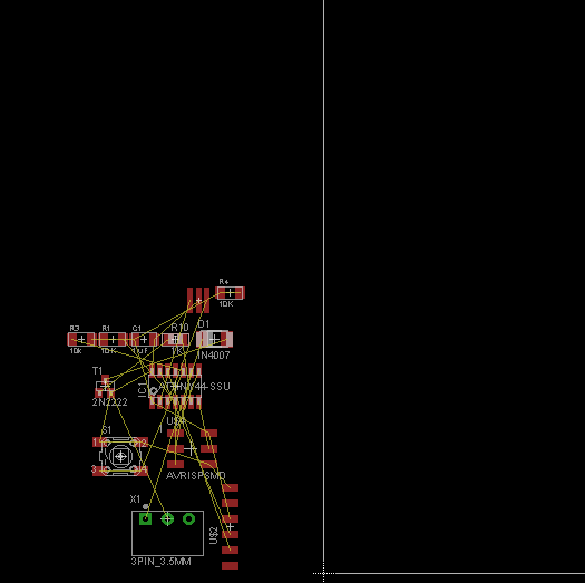
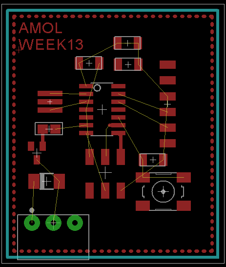
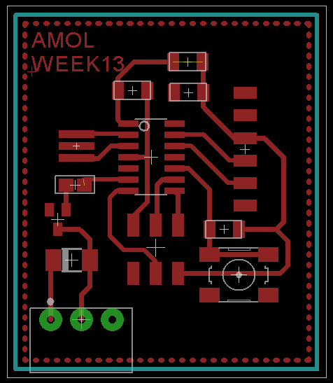
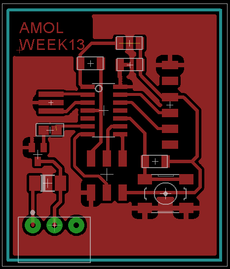
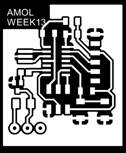
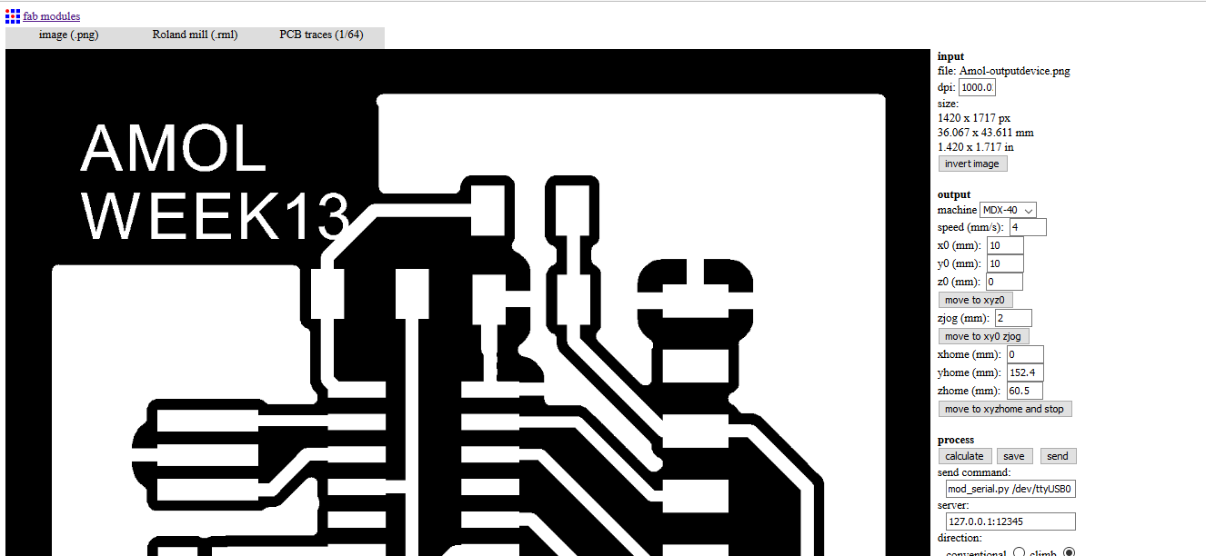
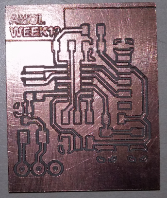
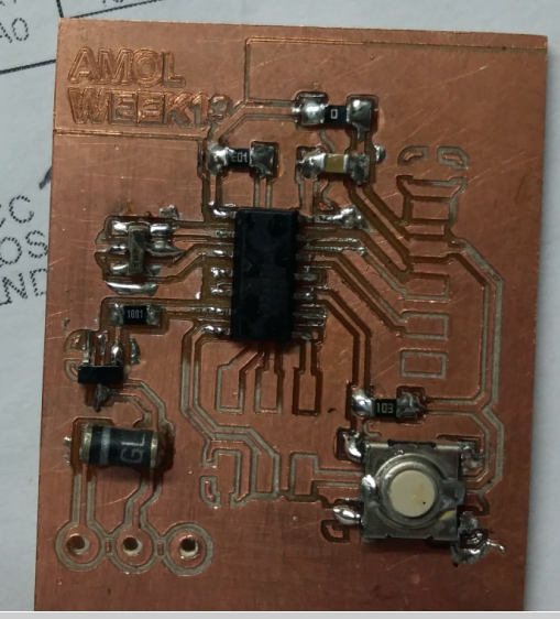
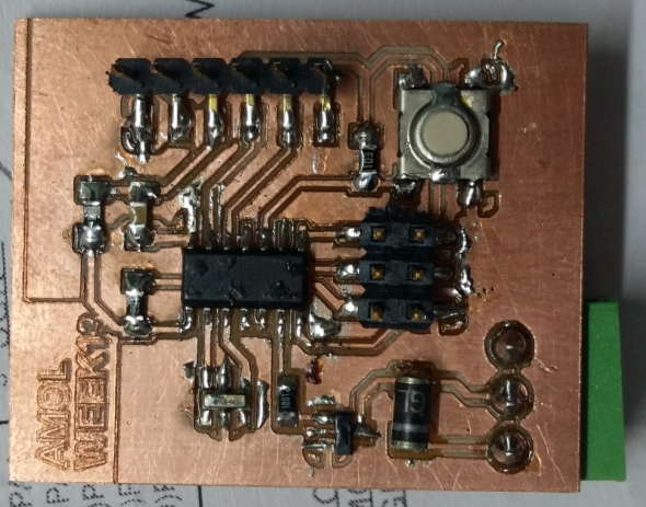
Milling and soldering the board
Wring C code using Atmel Studio.
   /*
 * Amol_Input_device
 *
 * Created: 06-May-17 10:38:08 AM
 * Author : Amol Wadkar
 */

//#defines
#define F_CPU 1000000  //Define clock speed as 1Mhz


//Include Header
#include     //Import header file required for AVR microcontroller
#include   //Import header file required for delay function


int main(void)
{
	DDRA = 0b10000000;  //set PA7as output & all other pins as input
	while (1) //Repeat the below actions continuously
	{
		if((PINA & (1<<3))==0b00000000) //When switch is press
		PORTA |= (1<<7);// Set PA7 high (Make SSR ON)
		else
		PORTA &= ~(1<<7);// Set PA7 low (Make SSR OFF)
	}
}
Program the board using Arduino.
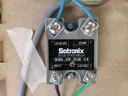
Connecting SSR module to the board
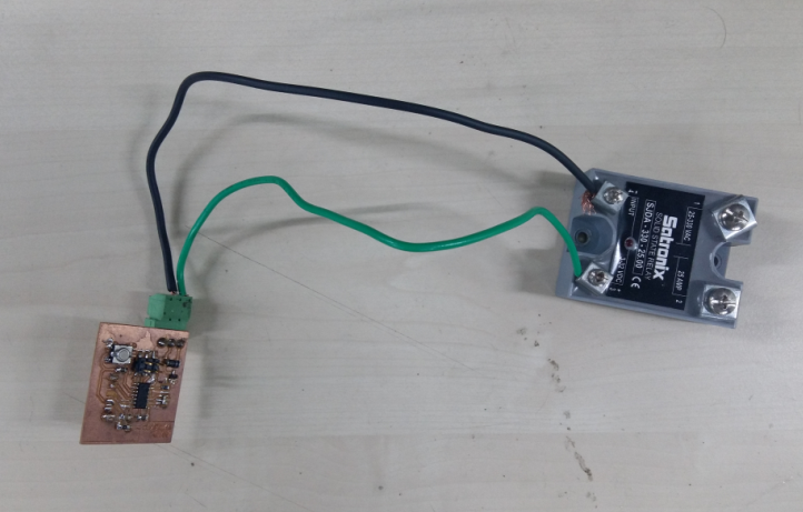
Working : Whenever switch is pressed SSR turns ON(There is a LED indication on SSR which indicates whether it is ON or OFF)