
W19 - Project Development
Project Proposal
Basically my project idea consists in make a LED matrix that light it on when receive a Laser pointer in it correspondent light sensor. Each LED must have a sensor to it works. The big picture of that would be a screen board which you could write with light, and each LED would basicaly be a "pixel".
The possibilites that I see to this project is to make something which people can interact each other. It will be also a nice opportunity to learn more about electronics, I would use the Laser cutter or CNC machines to build the box and make PCBs to the circuits.
The project is made to be some interactive small LED arrays that will interact with the user by a Laser pointer. Small nodes will compose it and when they are put together can be used as a small screen, and the user can use it as a board to write or drawn, where instead of using a pen will be using a laser pointer.
Bill of Materials
- a bunch of LEDs (red or green).
- FR1 boards for PCB.
- Laser pointers.
- resistors (for the LEDs and maybe some 0ohm resistors to jump traces at the board).
- AVR microcontroller (probably Attiny84).
- Pin Headers.
- 20MHz resonators.
- 1uF capacitor.
- FTDI cables to communicate to the computer.
- Translucent white acrylic boards.
- PLA filaments for the cover boxes (if 3D printed).
- Wood for the cover boxes (if laser cutted).
- Hot glue.
Design and laser cutting
Two tools that can help you in making boxes are: http://boxdesigner.connectionlab.org/ and http://makeabox.io/. I first used one of these websites and them exported as a PDF and adjusted my model in inkscape and corel draw.
Another important thing is that I wanted the nodes to be tiled, so the can become equally spaced from each other, and really looks like a screen when put together.
At this point you will need to figure out how to set your electronics design to match with your product design. I got the LEDs size, set a size for my LED matrix and then designed in Inkscape how spaced they needed to be from each other.
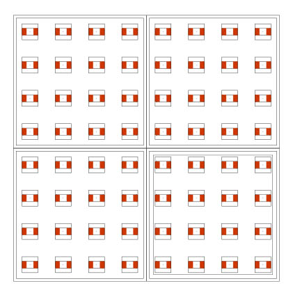
Then I made the boxes using the websites and adjusted in inkscape for cutting it.
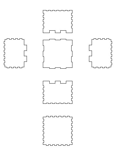
See that for the top face, I will cut it in acrylic, not in wood
You can get the files here:design.rar
Electronic Board
For the electronic board, big part of the development are on the input devices, output devices, and networking and communications assignments. For more detailed information you can go to these pages.
Basically I designed using eagle, making a 3x3 LEDs array as showed here.
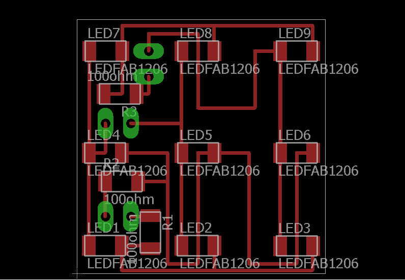
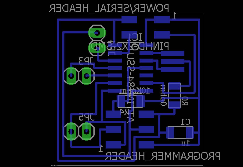
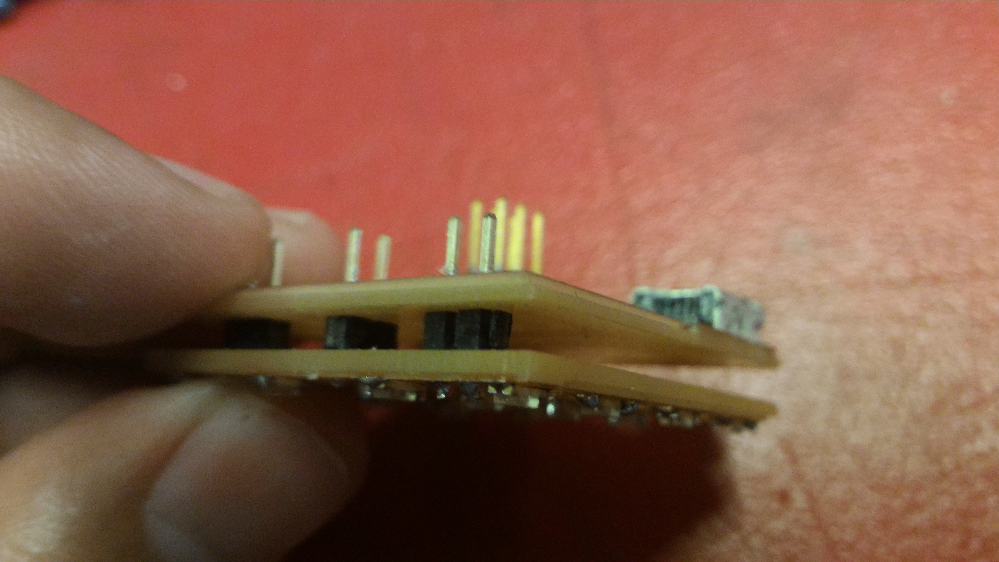
After design the board, I went to mill it at the Roland Modela. Note that I designed a double-sided board. As we do not have those boards, what I did was to solder some pinheaders connecting the two boards.
When you are designing like this, you need to remember that the bottom image exported from eagle need to be flipped using gimp or Photoshop. I used Photoshop CS6 to edit my images when necessary.
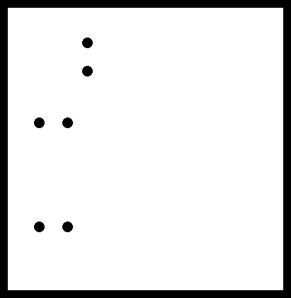
A different process here is that you need to make holes in the board so you can insert the pins. I put the holes in the same image of the board cutout, so you mill it as well. Here is how the files prepared for milling looks like:
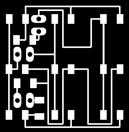
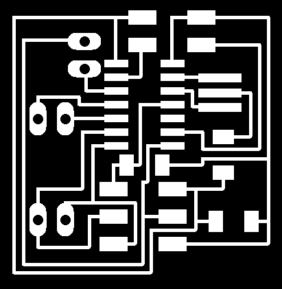
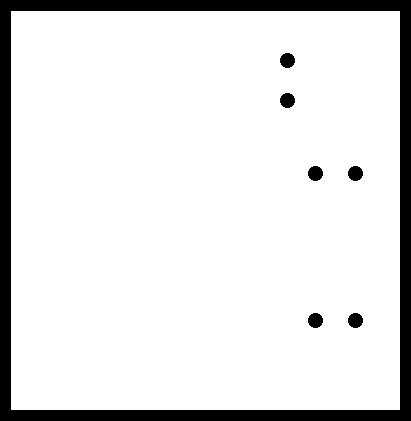
See that the bottom files to mill are horizontal flipped compared to the print screen from eagle showed before.
So I milled the boards because I wanted to make them to communicate each other, and started to stuff them with the components. Nothing new here, just solder all of them in the correct place.
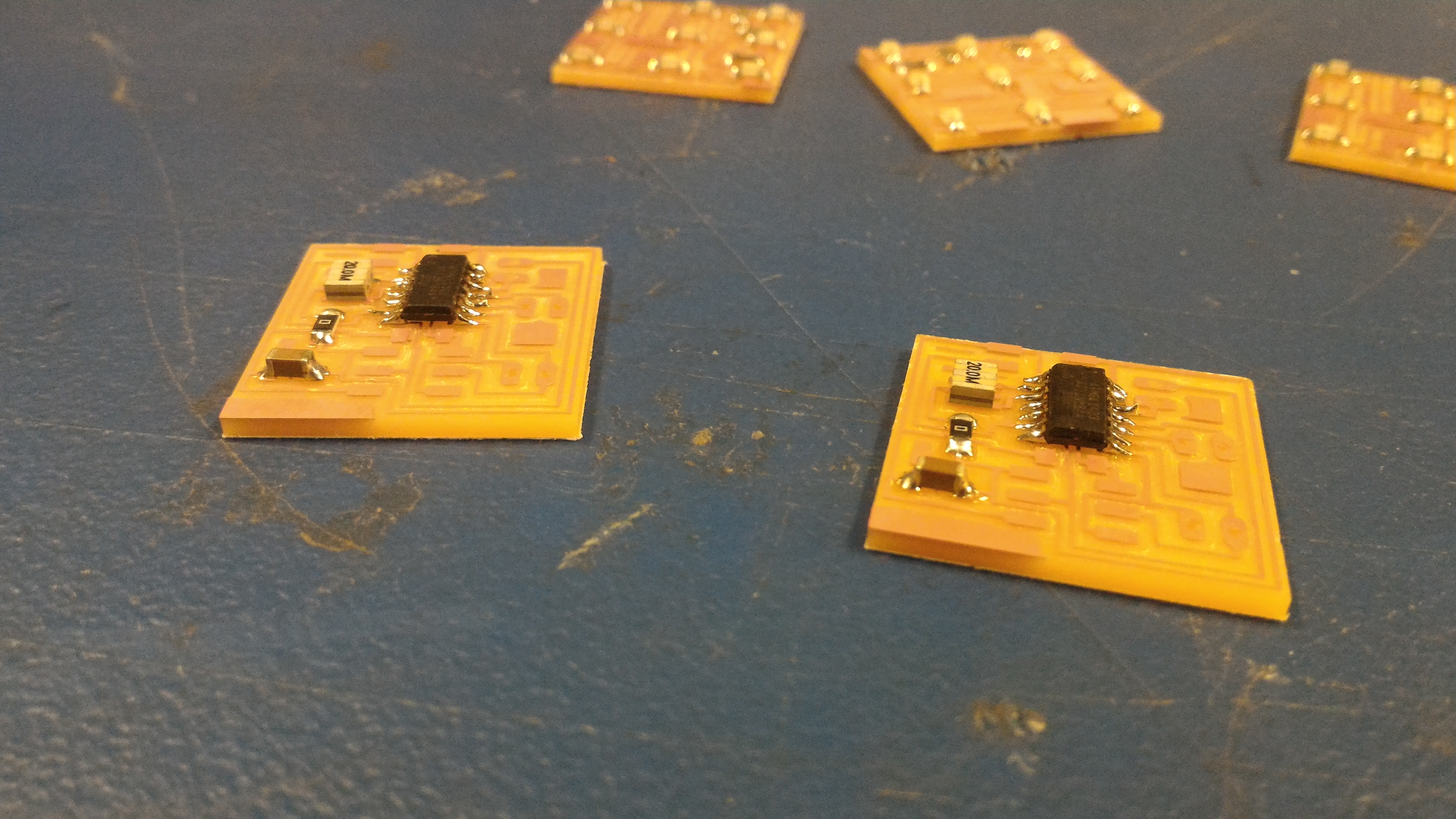
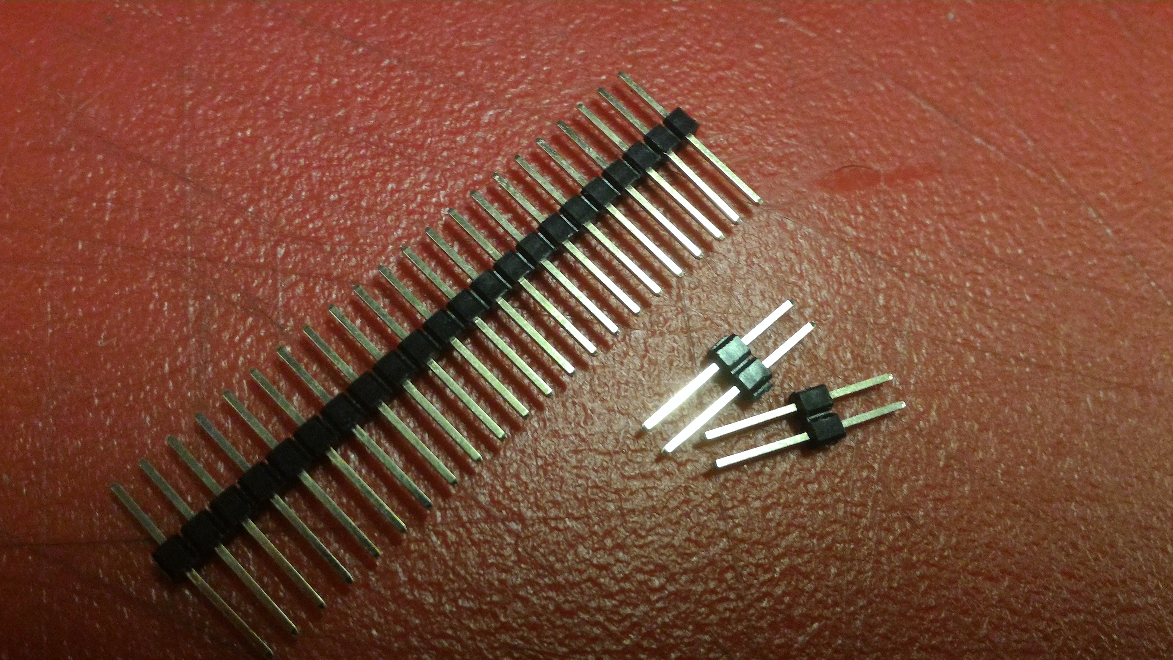
After solder the components, solder also the pins connecting the two boards. Here how are the pins I used and how I solder them together.
The files of electronics design and production can be found here: electronics.rar
Programming
Most of my microcontroller programming was made on the input devices, output devices, networking and serial communication and interface application programming assignments.
You can find the source files here: programming.rar
Final Result
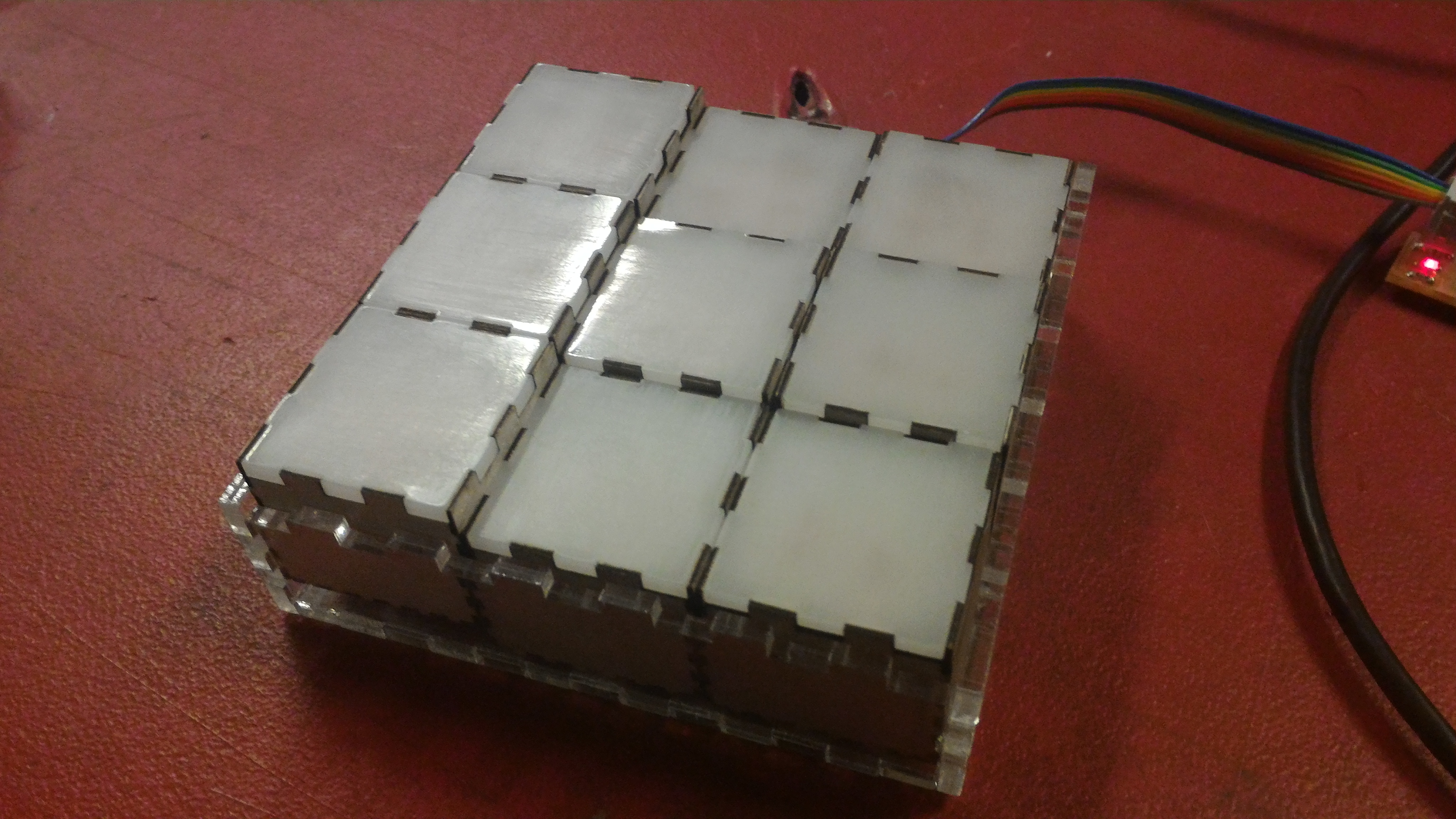
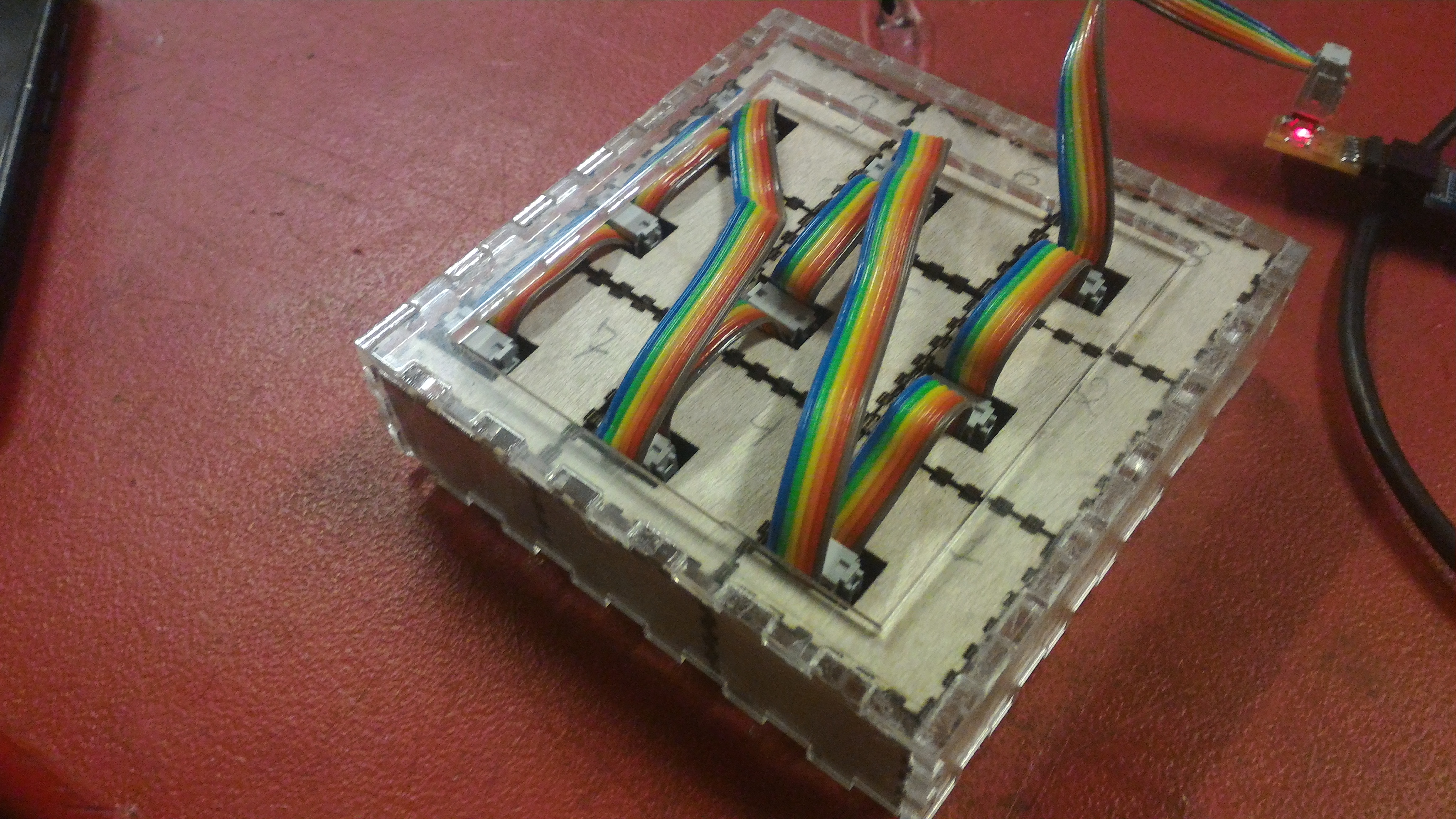
To make it works in the way I wanted, I needed to make more LED nodes to have a screen big enough to make some simple drawn using the laser pointer on it.
I made 9 nodes (3x3) and as shown before on Interface Application Programming week, and connected them together. I also networked them as shown in the Networking and Communications week
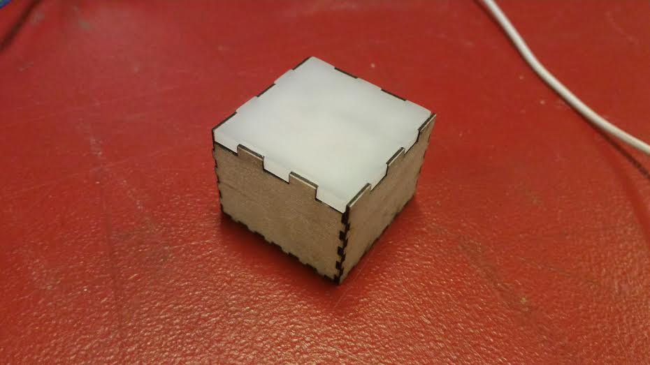
Here is how the final prototype looks like:
Project Development
I answered some questions about the project development, as showed on the week assignment
what tasks have been completed, and what tasks remain?From the applications and implications week, I had set the following tasks to be completed. I had completed all of them but check the comments for each one:
- Improve the communication between the microcontroller and the computer: I did improved it using serial communication, setting my own communication protocol. Also after creating the user interface it got easier to communicate.
- Create the user interface to allow control the LEDs from the computer.: I did it using processing. It is very simple but allow you to load an image from your computer, and send it to the laser nodes screen.
- Adjust the electronic design to connect the board in each other: I did it, before I had only one cable connecting each node to the computer. Now I can connect just one node to the computer and the nodes to each other. When sending information from the computer to the nodes, it go through all of them, but gets the message that is assigned (by hardcode) to each node.
- Decide what is the best for the cover box (3D printed or laser cut), design and make it: I decided to make it laser cut because we was having trouble with our 3D printers, and also it would be much faster using the laser cutter.
- Make a Pro-video of the final prototype: I did it for the final presentations
what has worked? what hasn't?I could not really communicate the nodes to the computer when they are connected together. What happened is that when each node send a information, it conflicts with the information from another node and then the computer could not really recognize what each node is saying, neither tell which node the information is coming from. So I still need to improve the communication protocol.
Still need to be resolved:
- How to solve the communication problem?
- Implement a debouncing for the LEDs.
what will happen when?- I will try to keep working on the project on my next vacations (probably in November 2016)
what have you learned?- I have learned a lot more on programming, mainly working with Arduino and processing. Also I learned more on how important is to make a good design. In my project I need to make the nodes match (or tile) perfectly to each other.