
The assignments for this week was just to make an in-circuit programmer.
The first step was to choose which type of in-circuit programmer to make. After checking our lab inventory, the option that we choose was the hello.ISP.44.
Before any work, I advise to check
1) Download the board files and save them in a USB
2) Go to the Roland Modela machine and stick your USB in there.
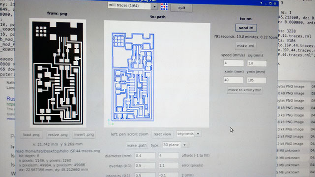
3) Open the Terminal and type “fab” the Fab modules will open.
4) Choose input format as "images (.png)"
5) Choose output format as "Roland mill (.rml)" or Roland Modela
6) Choose the process as "PCB traces (1/64)". This will choose some standard parameters for cutting on your machine. You can change some of them but it is not recommended.
7) Click on "Calculate" to check the toolpath of your process.
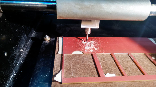
8) Then, follow this instructions on machining. The basic steps are:
- Put double-sided tape onto de board
- Lay the cooper board flat on the sacrificial layer
- Replace endmills and place the 1/64" endmill
- Place the tool at the origin, using Fab Modules. In my case I measured a approximated position with a rule and enter the data on the software.
- Leaving and checking the tool height (you can do it as in the video, or by pressing “down” button on the machine, until it barely touch the coper surface.
- Send the job and start milling traces
- Switch to the 1/32" endmill
- Place the origin again and cut it.
- Click View button
-Cleanup after yourself
-Remove de circuit
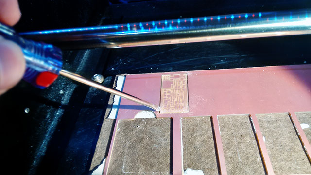
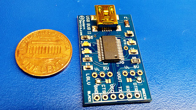
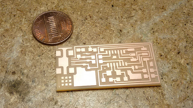
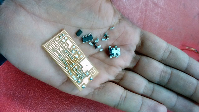
9) If everything gone right, you now should have a board like this:
After picking all the components It’s time to star soldering them on the board. A good hint here is to start by soldering the small components, and by inside the circuit.
First check out this page from Jean-François Duval. He gives three good links on surface mount soldering.
The way I do for all components is:
- Heat up the cooper pad
- Put a little soldering iron on the pad
- Heat up the soldering iron and stick one side of the component there.
- Solder the other site of the component. Try to heat up the cooper pad, the component first and then put the soldering iron. Waits it spread by the cooper pad surface and the component to make sure that there is an electrical connection between them.
- For the small parts (read microcontroller and USB head), use Flux. It helps a lot on the process.
- Eventually, you will need to use braid to take off some excess soldering iron.
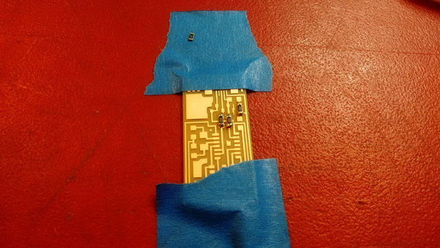
I started soldering, and to facilitate the process, you will need to fix the board. I used some blue tape to do it.
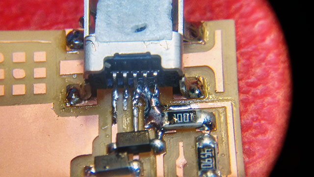
In my first attempt when I was just finishing the board by soldering the USB head, I burned out the traces of one of the pins because I didn’t use the Flux. It was very difficult to make a soldering bridge without to make a bridge to one of the other pins o the USB head. The picture above shows how it was after burning the trace and I tried to make the soldering bridge.
So I decided to start again, but reusing the components that I used in the first board. For that, I needed to use a hot air station and a tweezer to take them off. The steps are:
- Choose a properly noozle for the size of your components.
- Pick the component with a tweezer.
- Turn on the hot air station. Set the temperature, airflow, and point it to the component by a few inches.
- The board will drop and the component will remain in tweezer. Do it to all the components.
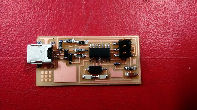
Then I made another board, and welded all the components again. Now I used Flux and was much easy to make it. Here how my board looks like.
Basically I needed to install the drivers and firmwares to use a programmer on my computer, so I would be able to programm my own programmer
I first tried to use AVRisMKii available at the lab to program my board. I was not successfull. I had some problems with the driver. I followed the tutorial available here to try to make it works. As the tutorial itself showed, there was a big red warning about using the WinAVR in Windows, because it was abandoned. I tried to use it anyway but failed. My computer got some blue screens in the process. Furthermore I recently updated my OS to Windows 10, it made it even worst and the software lest compatible.
Then I used Shawn's MAC to programm my board. Basically I followed the steps on the tutorial but now for MACs. Shawn has already installed the CrossPack and showed me the process throught the Terminal and the Makefile process
In our first try we got some errors on programming it. Then Shawn told us that there was a error that the programmer and the board wasn't set to the same speed of interaction, and we can change this parameter by changing the code in the Makefile changing the -B to 5.
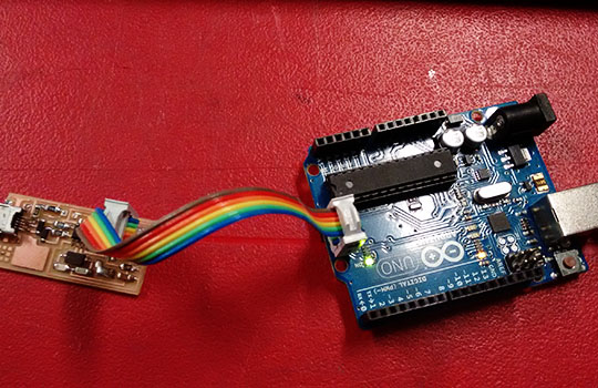
Then we finally programmed my board! But I was frustrated that we couldn't programm it on Windows 10. Later I realized that I could use the arduino as programmer to programm the atTiny84 following these instructions and them I arranged it to work!
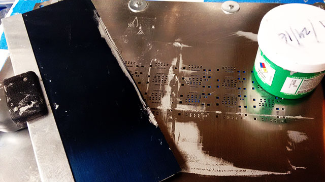
We also tried another processing for stuffing a different board, the reflow soldering, which is a process that you use a solder paste (a mixture of powdered solder and flux) so you can temporarily position the electrical components to their pads on the PC. This process alow to make the soldering process much easier and quickly.
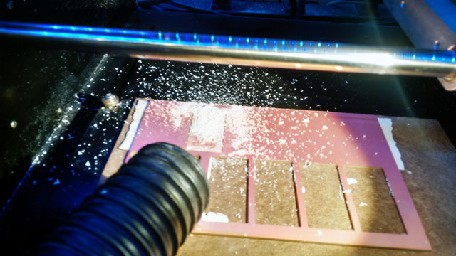
First you need to make sure the board its not a FR1 board, it needs to be FR4, otherwise you can burn your PCB while doing the process. This is how looks likes a manufactured FR4 board.
Then by using a special sheet cut to be the same size and positions of your pads, you can put the solder paste on the boards. Then you will be able to stuff your board. Its will stick a lttle bit your components, so its not that difficult.
Ater the entire assembly you put the PCB in a controlled infrared heat oven, which melts the solder, permanently connecting the components to the board.
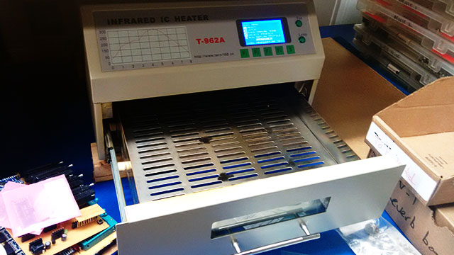
At the oven you need to set the correct parameters and heat curve for your board, components and solder paste.
After "cook" the board for the programmed time, give a little time to the machine cool down and then take your boards out. It is important to check your soldering using a magnifying glass or a microscope. Mine was okay, and here how its looks like.