
The assignment for this week was: make something big.
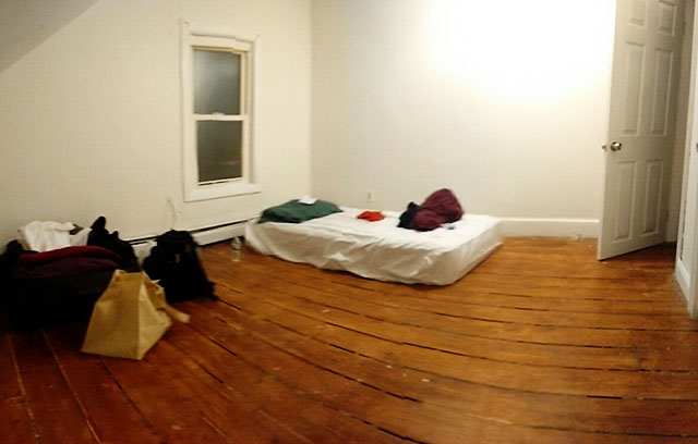
This is one of the weekly assignments that I was most excited to take. Since I arrived here I wanted do make a bed for me because this is how my bedroom looks like now:
I started looking for some different types of beds that I could make and I actually found some interesting ones. The one that most got my attention was the one of the video below and from this website:
Flat Pack Bed from spore on Vimeo.
But then I realized that the cool part of the design would be under the mattress, and also that this would be too big to make! So then I changed my mind, and decided to make something else.
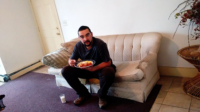
Other thing that I don't have at home is a dinner table, so when I am having lunch or dinner there, I sit on the couch, hold the plate with one hand and use the fork with the other. So I decided to make a table.This is how I have dinner at home, plate in one hand, fork in the other.
I found that a good design would be making something similar to a dinner tray table. I found several models on google but none of them the way I want. So I decided to make my own design.
I set some design rules that I wanted:
- I want something light or that I can load in parts to home, and do not need screws to assemble it.
- The size of the table should be big enough to serve as a dinner table, and as a desk to use my laptop.
- I need to be able to sit on the sofa and use it comfortably.
- I want to be able to adjust the height if I change from the sofa to a chair or stool.
Checking the materials at the Lab, we have a nice plywood 3/4 inches that I think would be nice. I will not be very light, but will be strong enough to make what I want. Then I made my design for a 3/4 inches plywood.
I started by setting the size of the table. I got a big ruler and tried to figure out a good size. Then I choose it to be 26 inches length and 16 inches width.
To make it comfortable to use sit on the couch, I cannot have the classical style of table with four legs, because the legs would impede to make the table get close enough to be comfortable. I imagined this table with "L" feet, where the bottom parts come under the couch.
For the height, the dinner tray tables usually has between 22 to 26 inches, so my design needs to have the height adjustment covering these values. To make the height adjustable I designed each leg using three layers of 3/4 plywood and the top part of the table will fit in a gap in the middle layer.
To lock the desired height, you can use a small piece of wood which will fit passing through two of these layers and reaching a pocket cut in the last one.
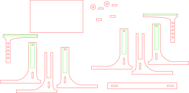
I made the design using Inkscape. To make it better to visualize, change the documents properties to the size of the bed of your CNC machine and start drawing. In my SVG I set the red strokes for cuts, and greens for pockets.
Then I realized that when I import them to Vcarve the colors does not matter, all of them will be black. To import your design into V-carve it is necessary first to export the drawing from Inkscape to a vector file, which V-carve recognizes. I choose .PDF, which does not have many problems with versions when importing to other software.
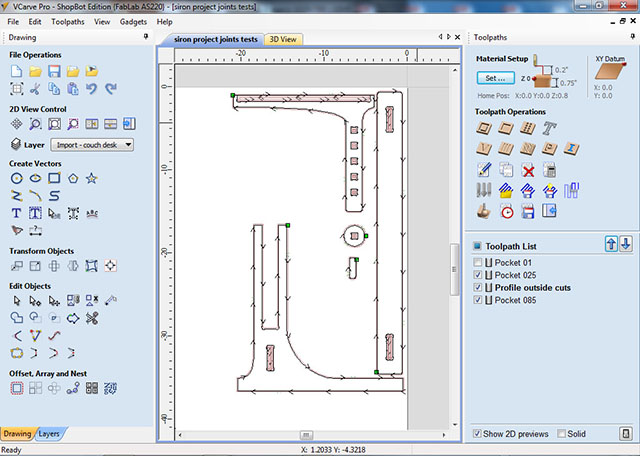
At Vcarve, I adjusted the design because for some features it is easier than Inkscape. I add a fillet "dog bone" style in the corners that I have some joints. In other, I add a round fillet to make it easier to fit. Also at Vcarve, I adjusted the sizes of the models, because from Inkscape the dimensions count on the stroke as well.
Also at V-carve it is possible to make some adjustments and set the better positions of your pieces and use less material. For that it is better to group your pieces, otherwise it gets each vector and move it alone. To group them you need to select the objects you want to group and press Ctrl+G
A good tip at V-carve, is the way you select the objects. If you left click, hold and drag from right-left direction among the pieces, you will select everything the selection area "touch". If you drag right left, you will select only what is inside the selection area. This is good when you are selecting objects that are near each other.
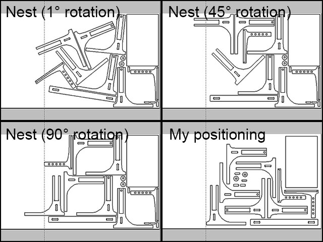
You can try to use the "Nest" tool to position your objects automatically, but I realized that it did not make a good work for my pieces, so I positioned everything the way I think it's better. Here is a comparison of several attempts I made using "nest" and my final positioning.
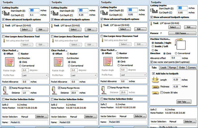
Then I started to prepare the design to cut, setting the profiles and pockets for each part on the design. I divided them into 4 styles:
- 0.1 inch depth pocket - present in four pieces of the model, and it is necessary to give space to the piece of height adjustment slide well.
- 0.25 inch depth pocket - to fit the top of the table and the locker of height adjustment.
- 0.85 inch depth pocket - to cut the inside parts. If make it using profile, probably will need tabs which will be difficult to take off, otherwise you can have small pieces flying into anywhere in the room (your eyes for example)
- 0.85 inch depth profile - to cut out the pieces. For this part, it is necessary tabs to keep your pieces fixed while cutting it.
I set all of them using a 1/4 inch up-cut bit, check below the general toolpath parameters I used
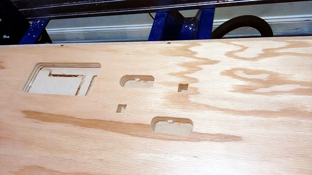
Then I started to cut the pieces. I first started milling some sample pieces, and then I milled the Pockets. It is a good idea to make the pockets first for two reasons: one is you can not cut them after make the profiles to cut the pieces out, second is if you need press-fit pieces, you can test them on the table, and adjust it before cut the pieces out.
Then, before cut it all, I decided to cut some of the pieces to make sure that they will fit properly. In my design some of the pieces needs to be press-fit, others doesn't. So for the press-fit pieces I set some allowance on the software in order to adjust them if the results does not come well. I cut first some sample pieces and then made the pockets where these sample pieces will be assembled. I started making the pockets with 0.01 in allowance. After testing the sample pieces on these pockets I noticed that 0.01 was way to much. Then I changed the allowance a bit lower and repeated the process several times till find a good match. In general they are around 0.005.
To make it faster, I first started with just one hole, and once I get a good press fit I replyed to the other pieces that has the same cuts. You can notice from my file that some of the "pocket" are not really pockets. What I did was, instead of make profiles make the inner cuts of a piece, I made pockets, so this way I does not need tabs to hold them, and get a better shape for the press-fit. So I made the other pockets in the board.
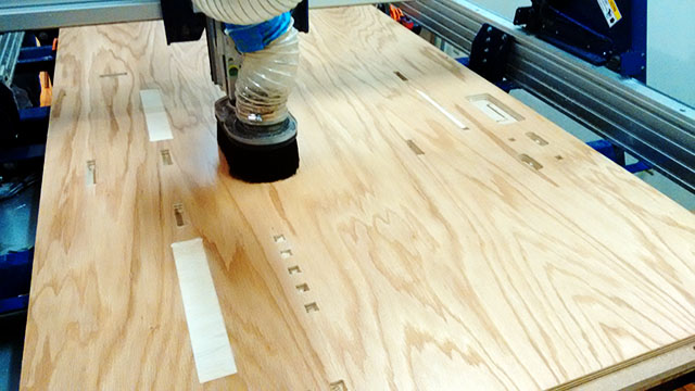
After mill all the pockets, I started cutting out the pieces. For this case it is important you set you parameters to cut outside the line, and make sure you add the tabs.
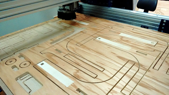
Them, I took off all the pieces and assebled them together. My project was supposed to be ready. After assemble it all I noticed that the feets was not very stable. I do put a piece to make them stay togheter, but at the top part of the feet, the piece was benting a bit. Another problem that I found was that the top of the table was also not stable. So i got a ruller and a caliper and made some measurements in order to make some new pieces to fit on my table to make it stronger and steady. I made other two pieces to put on the feets, and two more to the top part. With these pieces I think the table would get really steady.
After design, I started again the process of milling on the board. For all of these pieces, I need them to be really tight to the others, as they need to be press-fit. I repeated the process of set some allowance and decrease this value untill find a good fit. To thest the fit I needed to put the feets on the board, without cut ou the piece.
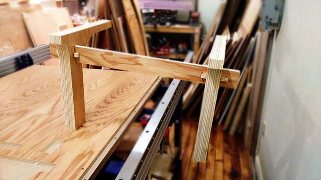
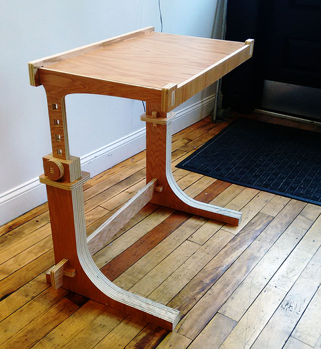
After make all the adjustment pieces, I assembled the table, and here is how it looks like.
You can find the V-carve file of my project here: dinner tray table.crv