
For this week the assignments was:
- Test the design rules for your printer(s) (group project)
- Design and 3D print an object (small, few cm) that could not be made subtractive
- 3D scan an object (and optionally print it) (extra credit: make your own scanner)
So the first thing was try to print the "constraints" model available on Thingiverse, to check the design rules.
On the Thursday night class we learned the basics of how to use the 3D printer and then we tried to print the model for testing. We started to print it, and it was going well, as it was already late, we let it printing over night, but them, on the next day we arrived and the print was like this:
So, we tried to figure out why it did not work. For this first attempt, we used standard settings of Makerbot, just changing the temperature to 200° C.
So we tried again using different using the same parameters, but I changed the infill type to linear, but again the print failed.
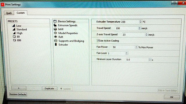
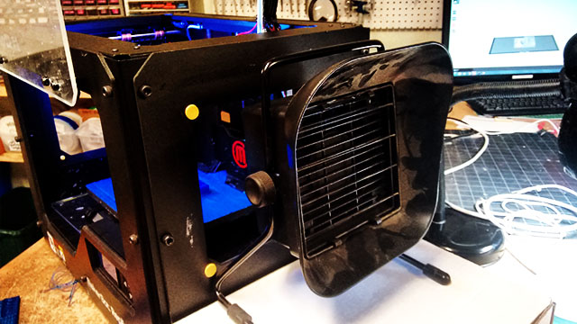
Then we realized that maybe we should change all the parameters. We got in contact to some people at Johnson Wales University, because they also have a Makerbots. Actually, they borrowed two print for us for this week of the Fab Academy, so more students could print their models at the same time. They advised us to print with the hood off, door open, and a small fan blowing on low from the side. Bed at 60, extruder at 220. Just like this:
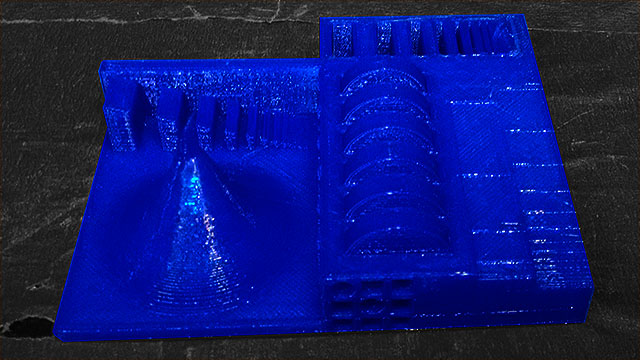
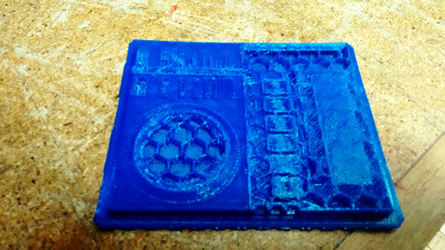
After set these parameters we tried to print it again, and it finally works. By analyzing the printed model, we can see that our 3D printer has some limitations. First is for high spots the model bended. I think it happened because as the printing area at this spot are small, the material don't have enough time to cool down and get hard enough for the next layer. It would be nice if the software recognize it and print in slower speeds on these points.
Other thing is for small holes or structures the printer cannot make it because of its resolution, so we need to take care with the model regarding tiny details.
It seems that it made bridge quite well by looking at the side bridge at the model, but I also thing that the side fan helped with that, by cooling down the material faster.
So for the 3D print object I wanted to make a 3d cube maze, which you use a metal sphere to make the maze path. The idea is to make the maze walls with a T shape on the surface, where in the bottom parts you can fit the sphere, but the top part as a T shape, does now allow the sphere get out of the maze, but do allow you to see where the sphere is.
So first step was to find a 3D cube maze. I found a nice draw at this website. I copied the image to inkscape and drew it again as lines. Then I made these lines stronger and transformed it into a path.
Thinking in the 3D printer, to make top part of the "T" I copied the firs paths generated and made them even stronger. My plan was to extrude these parts in different highs and then merge it together.
The final drawing model at inskscape can be found here.
Then I used 123D Design to make the 3D model of each face. To make it works I need each face very well aligned. So I saved three .svg files for each face, one for the base, other for the walls, and other for the top of the "T". I imported these SVGs into the 123D Design and extruded each part separately. The base with 2mm, walls with 12mm and the top with 2mm. I moved the top to the top of the walls and then I merged it all together.
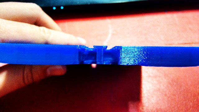
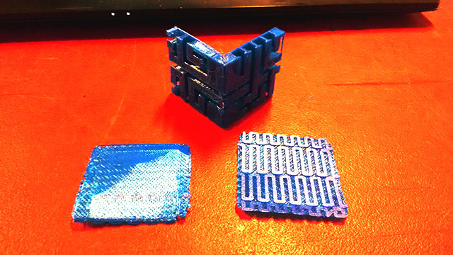
The sphere that I found and wanted to use is 5.5mm diameter. Therefore, before print the entire model, I printed just one face to see how it would works. I used the same settings for the constraints print and here is how it looks like.
It was quite successful, but I had a problem with the T shapes. As I did not use support structures, some of the first lines of the top fall down to the base and I had to take all them off. Also I found it was too big.
Then I decide to change the model by making a chamfer in the bottom part of the Top of the "T", so we do not need support structures to make it. So I had to select all the lines to chamfer, and chose a chamfer of 1mm.
Then I found a smaller metal sphere that I could use. So I adjusted the scale for a 75%, which would fits well for the 3,5m diameter sphere that I found. So in order to test, I cut just a part of one face tried to print it quickly to see if the new sphere would fits. I set to make support structures. Then after have it print, I realized that the support structures was too difficult to take off from inside the maze. So I decided that I would need to print it without support structures.
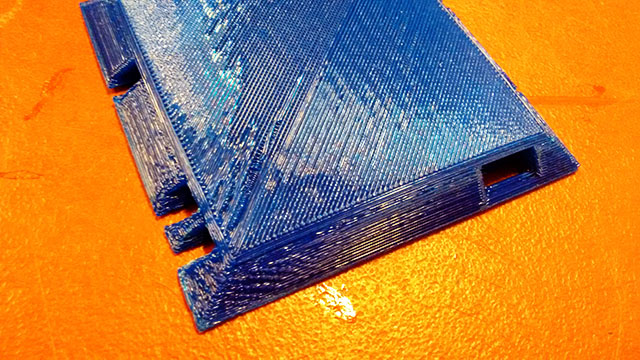
Another challenge is that if I want to print the entire cube at once, it would be almost impossible to print without support structures in a FDM printer. Then talking to some of the last year Fab Academy students, I decided to print each face separately and glue it together after all. So I needed to make joints for each face, by chamfer it in 45°. So I went back to 123D Design and started to work. I created a block of the size of the intersection of each face, made a copy of this, chamfer in 45° of the properly side and then subtract it from each face. I needed to make it for all the side corners.
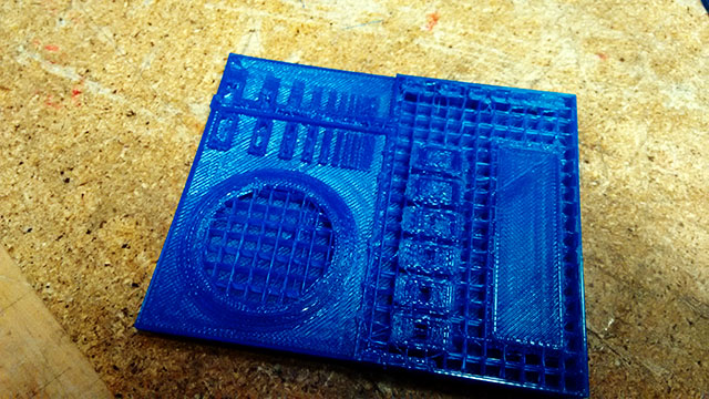
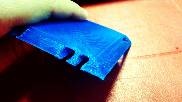
I made it for two faces and printed them, now without support structures, but at the first attempt, I did not set for raft. So one of the pieces did not stick at the bed well, and here what I got:
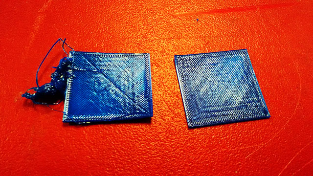
I think without the raft the area of the pieces was too small to stick well, so for this piece it is better to have the Raft. Then I changed the parameters at the Makerbor software to add raft on the parts and tried again. Then I got it right. I used superglue to glue the parts. At first I used too much superglue, and it was not gluing at all. So I cleaned it, and used some plastic bonder activator, and it worked pretty well. I waited till it dry and checked if the sphere pass through the joints. It worked well.
So I continued with the print, now all the sides. I set to print two faces at once, so I can make it faster.
First I had problem with one of the faces. It bended a bit so when I tested the ball into in it was no passing in two paths of the maze in this face. I tried again but the print failed. So I realized that I need to change the blue tape because it was already taking off from the printer bed. So I changed the Blue tape and did it again, and it works.
After print all the faces, I glued them together. In order to glue it better and easier, I also used an activator. You need first to put a bit of activator in the plastic, wait a bit, and then put the glue.
Press and hold the pieces together and wait until you feel that the glue is dry. You will have some challenge on glue more than two faces at once, because you will need to glue many joints at once.
I also noticed that my design should be corrected because when 3 paths of the maze meet, the ball that I have pass trough it. To not print everything again I fixed it gluing some small parts of the raft on these points.
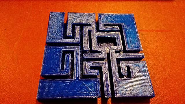
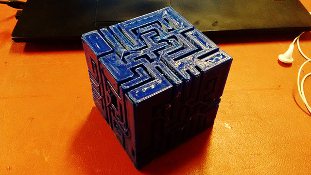
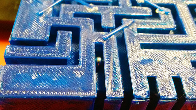
Here how the finished maze looks like and the ball inside it.
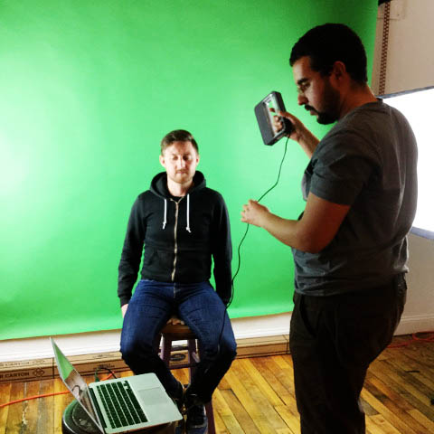
This week we also got to try 3D scanning. The scanner we used is called Sense, which was a handheld device that we hooked up to Drew's laptop. I tried to use to my computer, but I think the Sense software does not deal well with Windows 10. This was the first trouble that I had
Drew, Ryan and I all took turns scanning each other. We realized that lightening was very important to achieve better results, so we decided to use some strong light reflectors, used for photography in the Media Arts lab at AS220. We also used a green screen back drop in hopes that this would be most easily distinguishable from the object or person being scanned.
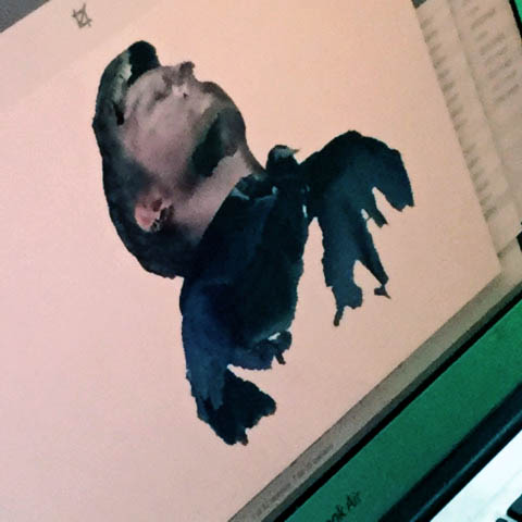
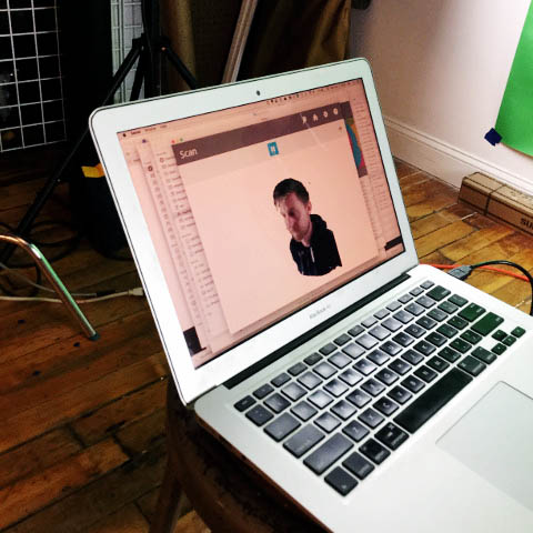
In general, this was a pretty cool exercise, although a bit challenging when the scanner would lose its point of reference. This happened a few times when I was trying to scan on Drew's hair. It was difficult to allign the scanner to its last point of reference by watching the computer screen, but moving the scanner in your hand around the person being scanned. If we were able to do this, we could continue with the scan, but if not, then we had to abandon it.
After scan Drew, I tried to use the software to export a STL and try to print, but we had some holes on the scanning, and the final result didn't come out very well, so I decided not to print it.
Here some pictures of the scanning process
You can find the source file of 123D Make here: 3d_maze_faces.rar
In this rar file there's also a assembled maze to you check out how to glue the faces together. But is the assembled model I did not made some changes necessary to a better print, is more to guide you on the assembling.