
The assignments fot this week are:
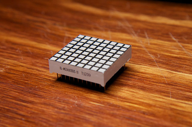
This week is focused on learn how to use a set of several software of design and drawing, in 2D and 3D. There is a bunch of them to try, but I chose just some of them to try, based on previous experiences or on how important they were recommended. To learn how to use it I tried to design a part of what would be a piece of my final project. A LED matrix composed of 64 LED (8x8). At the end it should seems like this:
The datasheet of this LED Matrix can be found here.
Adobe Photoshop
When I was younger, I did a course on web design, which is how I learned a bit of HTML, PHP and Photoshop. At that time, I got very interested in Photoshop and stated to learn it by myself. As my mom is a Photographer I started to work for her doing some adjusts on the photos that she takes. So working with Photoshop is not a secret for me. Because of that, this is the software I prefer to use for image editing and bitmapping.
GIMP
Even knowing how to use Photoshop, I tried to use GIMP as well because it is open source and is always good to know more tools that I could use. I found it very similar to Photoshop. It is quite easy to use if you already know how to use Photoshop. It also works with layers and it is a good tool to edit the size and resolution of your pictures.
I used it to make a GIF image of the process of making a model on Fusion 360 that you will see below in this page.
I just followed this tutorial to learn how to make it.
Therefore, I shot many print screens on the main steps of my 3D model construction process, pasted this screens on separated layers on Gimp and exported the file as GIF. When doing that you will want to to select the option "As animation" so each layer will be a frame of the animated gif.
Corel Draw
This software was not listed in the FabAcademy website but as it is also for vector drawing, I thought that could be valid talk about it. I also already know a bit of CorelDraw from a course that I took in Brazil. I worked for one year doing vectorization, typesetting and diagramming some handouts and booklets while I was in high school, and Corel Draw was the software that I used to do that.
Inkscape
Again, as I know how to use Corel Draw, it was not that difficult to use Inkscape. They are also similar, but the interesting thing about Inkscape, besides being open source, is the "Clone" feature, which enable to change a set of objects by changing just the first model.
What I did using this software was try to draw a 3D representation of the LED matrix, so it would be as a 2.5D design.
1) Draw a rectangle at the size you want
2) Transform it into a path
3) Use the "Edit paths by nodes" to adjust the model view. I selected the two nodes on the right site of the rectangle. By keeping pressed "Ctrl" while clicking in a node and dragging it down, you keep the direction.
4) Copied the first rhomb and aligned the right face of one to the left face of another. Use "Object>Align and Distribute"
5) Select the two top nodes o the copied rhomb and drag it again to the desired position.
6) Make a copy of the top surface rhomb and scale it in the estimated size of the LED. After rescale it, use "clone" for adjust.
7) Now if you adjust the size of the first LED, all others will adjust it automatically too.
8) Adjust the position of the first and the last LED in this column.
9) Use Align and Distribute again to position all of them. I selected the entire column and used "Distribute Center equidistantly" horizontal and vertical.
10) Select and clone the entire column to place more LEDs. Don't worry with an exact position of the middle LEDs, worry about only for the first and last columns.
11) Select and align line-by-line and column-by-column using "Distribute centers equidistantly" horizontal and vertical. Now that's start to look like a LED Matrix.
12) Press F2 and click twice on the bottom lines of the sides to add nodes and make the feet of the LED matrix boxes. Add 4 nodes more, near the corners. Select the two most inside the line and drag it up.
13) that is it! Now just change the color of your drawing to make it look better.
Below you can check these steps in a GIF.
File: LED_inkscape.svg
LibreCAD
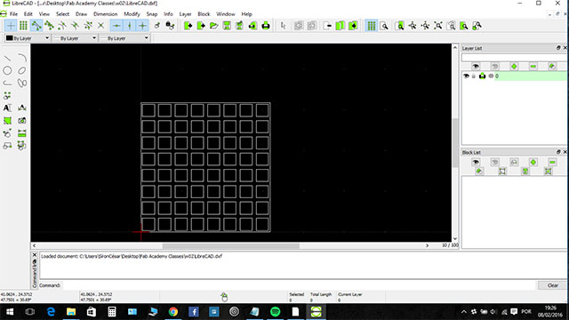
I tried to make it in LibeCAD just to learn make it again, but then I reminded how painful was to drawn on CAD from the Basic Technical Drawing class that I had at university. It is a great software if you need really well positioned and scaled drawings as top/bottom or sides views. I made a top view from the LED matrix and that's it.
File: LED_LibreCAD.dxf
NX
I learned a bit about this software at University in the class of "Computer Aided Manufacturing Process". It is a very good tool but is not very intuitive. We can use it also to make some simulations related to stress analysis, structural analysis and other features. As I learned it, use other software for 3D design can be interesting and again, it makes me get how to use others software easily. However, I do not have this software in my computer, so I did not try to design the LED Matrix on that.
123D Design
I designed the same LED matrix at 123D. The software is very intuitive so had no many difficulties using it. Here what I did:
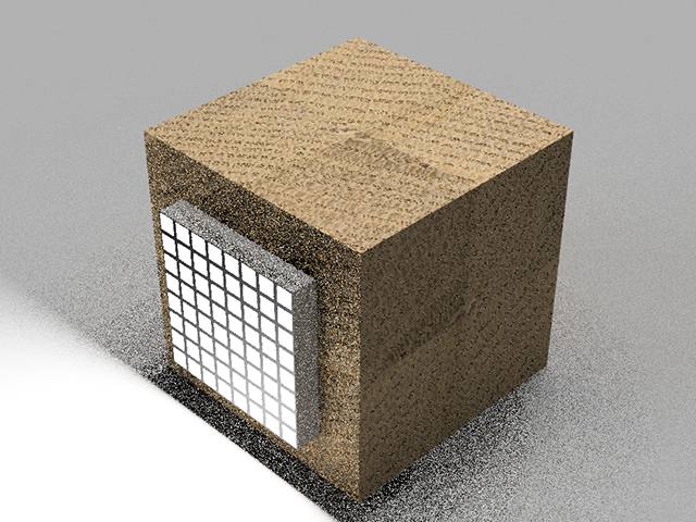
1) Create a Block in the size of the LED Matrix.
2) Copy this block and drag it up.
3) Make a "chamfer" of 2mm on all the top corners.
4) Make four copies of the chamfered block and position it 1mm of the bottom face of the main block, and drag each of them to one of the sides.
5) Use the "combine>Subtract" tool to make the feet of the LED Matrix box.
6) Create a 3x3x1 (mm) LED and position it on the corner of the top face of the matrix box.
7) Change to the Top view and make copies. Move them to get 1mm distance from each other.
8) After make an entire line, you can select this line and make a copy. After that, you can select two lines and make another copy, so you will have four lines. Finally, you select the four lines and make another copy, so you get the eight lines you need.
9) To make it looks better, select the big box and change it appearance, by choosing the material and color.
10) You can also select the LEDs and change it color and materials as well.
File: LED_123D.123dx
SketchUp
I tried to use the SketchUp to make again the LED Matrix, but it was very different of the software that I am used to. The time was running out, so I skipped it for now to try the Fusion 360, which was highly recommended to learn. However I would like to try it better following a tutorial to learn it, and I will try to do it soon.
Fusion360
I also tried the Fusion360. The process to use it its quite similar to the 123D, as both of them are from Autodesk. The only difference is Fusion360 has more features, which allow you to position and align the objects better. In addition, it has more type and qualities of materials in its library. This software was the one that I liked most and probably I will be using it to make the 3D designs during the course.
You can check the final rendered image and just an animation with the designs that I made:

As this software is the one that I laked most, I also did some other parts for training on use it. You can check it all below.