
This week assignement was: "measure something: add a sensor to a microcontroller board that you have designed and read it."
This week is very related to my final project, and as the time seems to be clicking faster each week, I decided first prototype using Arduino, and then for the final project I will make my own board with the microcontroler.
For my final project I want to make some modular LED matrix, where you will be able to light up the LEDs on these modules, by using a laser pointer. So basically I would need light sensor to recognize the laser pointer, do some programing with this information and then light up the respective LED to this light sensor. You can get more information on my project page.
By doing dome research, I discovered that I could use the LED as a light sensor instead of having a light sensor for each LED. The LED is basically a very bad light sensor, but as the light of the Laser pointer is pretty strong it could work.
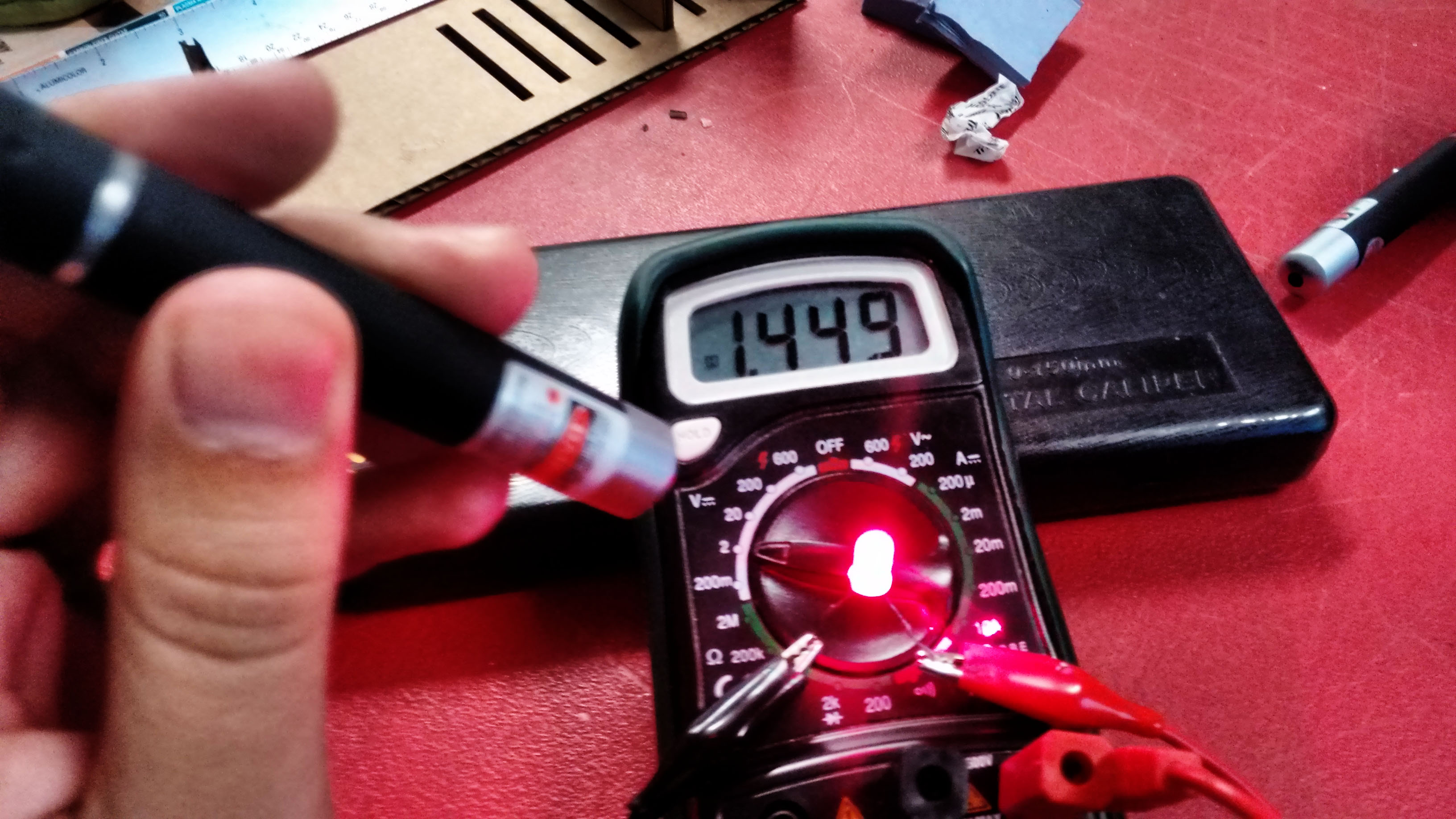
And it works! To try it yourself, get a standard LED, and a laser pointer with the same color (for example a red LED and a red laser pointer). Conect the LED to a multimeter at the direct voltage measurement function, connecting the anode of the LED to V at the multimeter, and the anode of the LED to the COM at te multimeter. Then if you point your laser direct to the LED capsule, you can see that it will generate a small voltage that can be recognized by the multimeter in my case around 1.4V.
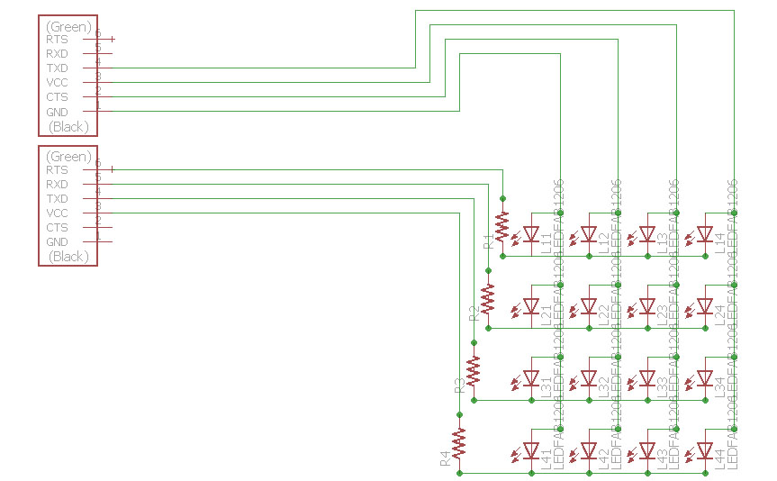
Knwowing that I first tried to do it by using a breadboard and an arduino. I made a LED matrix using 4 LEDs (2x2) and it kind of worked but it is not the type of the thing that I would advise you to do. The connections using the breadboard was very instable and was pretty dificult to point the laser correctly to the LEDs. Therefore I decided to make a board for my first LED matrix. I made a board with 16 LEDs (4x4). To make a better use of the microcontroler ports, instead of using one port for each LED (that would require 16 ports of the microcontroler), I made them as the standard LED matrix as this one from Adafruit, connecting the cathodes of each LED line, and anodes of each LED column, this way I would then need only 8 ports (4 lines and 4 columns), and I could check if the laser is being pointed for each LED specifically because each one of them has his "addres" of row and column.
I needed also to put some resistors for the LEDS, but again I wouldnt need one resistor for each LED. Actually I need only 4 resistors, that could be connected to the anodes (columns) or to the cathodes (row). I used Eagle to design the LEDs board. I first tried to make a design conecting to the anodes, but them to make the routing would gets very complicated. I noticed that connecting them to the cathodes would be easier to route everything. To make it easier to connect to the arduino board, I added two FTDI headers that I would connect some jump wires to the arduino. At the end this is how the eagle file and the board traces looks like:
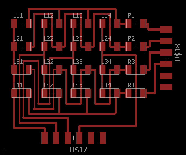
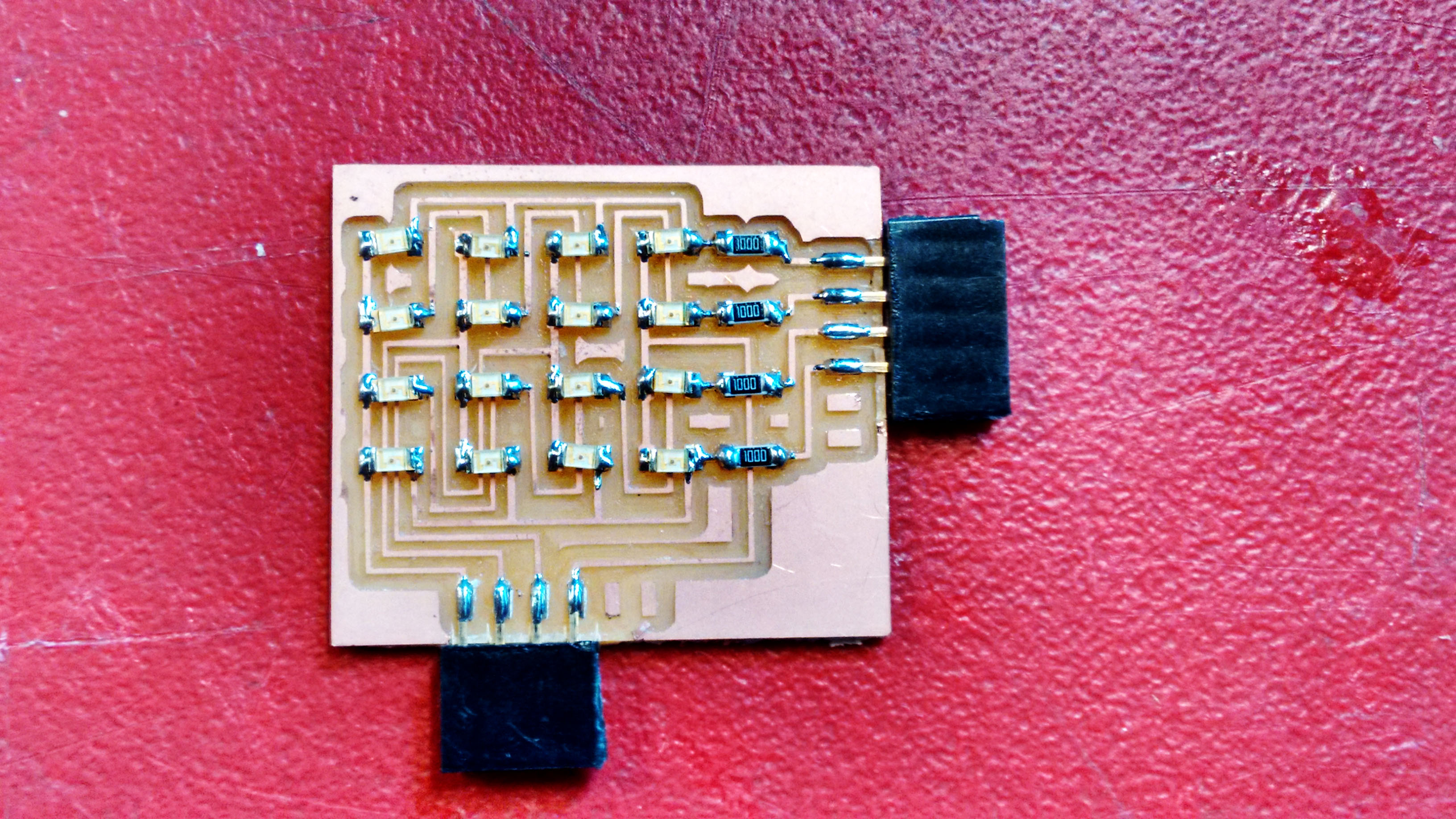
I milled the boards using the SRM-20 and Fab Modules, just as we larned at the electronics production week. The first board didn't comes out very nice and there was some traces that was not really well cut. As there are some LEDs that there is two paths under them, I had to change the route width to 0.016 and mill it again. Also for the second time that I milled, I used a new bit, because the previous one did not give me a well finished board. After mill it and solder all the components here is how my board looks like.
Then I started to work on the coding usign Arduino IDE to read the voltages at the LEDs when I point to them and I realized a problem! I don't have enought analog ports to read all of them. So I decided to conect the columns to the analog ports and make a small code to identify which columun I was pointing, and then work on indentify the rows later.
The main fuctions to make it are:
- Arrays - A collection of variables that are accessed with an index number.
- pinMode(); - Configures the specified pin to behave either as an input or an output.
- analogRead(); - Reads the value from the specified analog pin.
- digitalWrite(); - Write a HIGH or a LOW value to a digital pin.
- Serial.print(); - Prints data to the serial port as human-readable ASCII text.
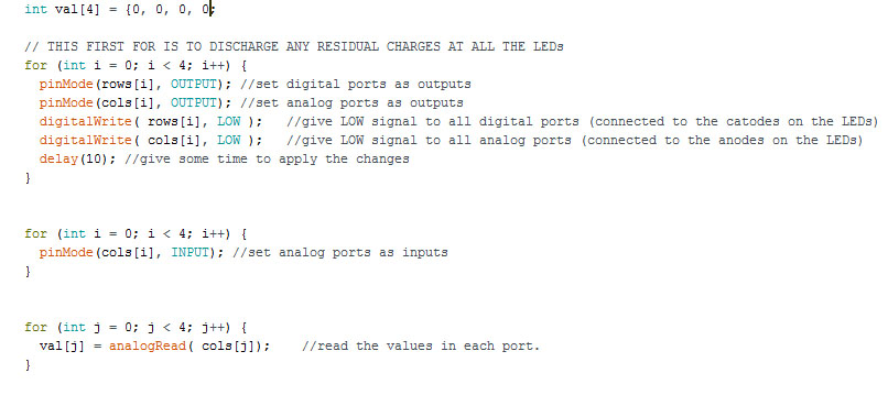
Basically you need to directly measure the voltage generated by the charged LEDs as this:
1) Discharge all current stored in the LED by making all ports LOW.
2) Measure voltage at the analog ports using analogRead().
In my circuit, the voltage is around 1.4V when the LED is pointed by a laser pointer. This is not enough for digital input to become HIGH. But, the difference can be detected by analogRead(). I connected the columns at the A0 to A3 ports using a Arduino Leonardo. This is how this part of my programming looks like:
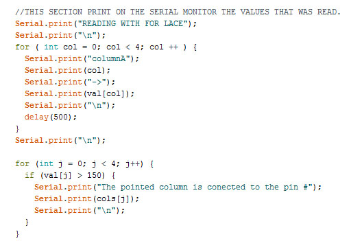
To see the range of measurements of each port you can use the Seral.print and print the values of the variable where you saved the analogRead values. After see the range of measurements once, I added another for() to identify the port of the column that was being pointed and also show it on serial print. This is how this part of the code looks like:
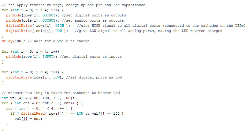
Now I had other challenge. I would not be able to analogRead() the values on digital ports for two reasons, first, as mentioned before, the LED does not generate enought voltage when laser pointed to reach a HIGH level that could be recoginized by the digital port, and second because as these ports are connected to the cathodes, the voltage generated would be negative. By doing some research again I found here a technique that we charge LEDs by applying reverse bias, and, then, measure how quickly the charged current leaks after stopping the reverse bias, making these steps:
1) Reverse bias the LEDs by making digital ports HIGH, and analog ports LOW.
2) Make digital ports INPUT. Initially, both of them is HIGH because of current charged in the LEDs.
3) Then, as the current leaks, digital ports becomes LOW after a certain period.
The time required for the leakage to discharge the LEDs is inversely proportional to the brightness. So, if a digital port becomes LOW quickly, we can know that this line is pointed by a laser pointer.
Therefore, by using these two technique by turns, we can detect which LED is pointed, by identifying its column and row.
For this case, the important function to use is digitalRead(). I connected each row to the digital ports 2 to 5 at the Arduino Leonardo. Here is how this part of the code looks like:
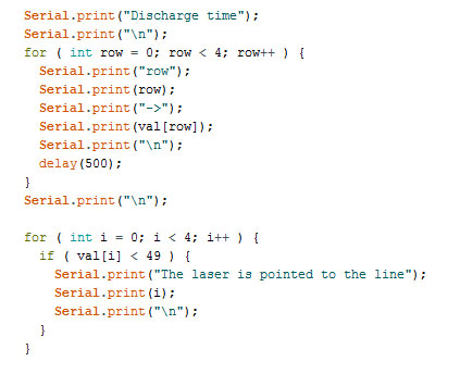
Again I wanted to know the values that I was getting by this techinique and make sure that it works, so I used Serial.print() to get the values for each row and used another for() to identify the one being pointed. Here is how this part of the programming looks like
Some improvements that could be made are make my own microcontroler board (that I will make for the final project), use port manipulation to make the reads faster.
All the files I used for this assignment are available here:
- Eagle Files: somatriz.rar
- Board Traces png: traces_LED_matrix.png
- Board Cut png: interior_LED_matrix.png
- Programming for read analog values: analog_values.ino
- Programming for read the discharge time:digital_discharge_time.ino