
This week assignments was:
- Read a microcontroller data sheet
- Program your board to do something, with as many different programming languages and programming environments as possible
Reading long datasheet was always painful for me. During my undergraduate course, I usually get the summary versions of component's datasheets and read only was necessary in order to make my projects.
Trying to comprehend what the Attiny84's datasheet in deep was a quite a challenge because there they explain many things related to its construction and how it works on the hardware side, talking about their registers, memory addresses and etc.
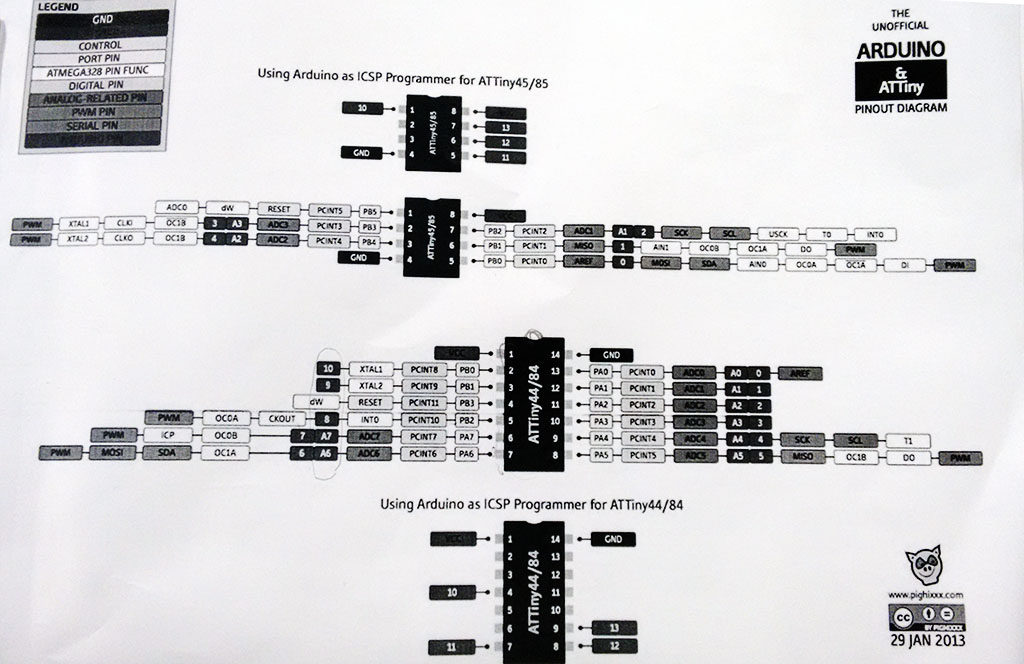
For me, the most important things in the whole datasheet is the association of the pins to their coding representative numbers, which tells you if there are special "needs" for the chosen pin. An interesting thing is that here at AS220 we have a summary for different microcontrollers to compare them and have a quick access to this kind of information.
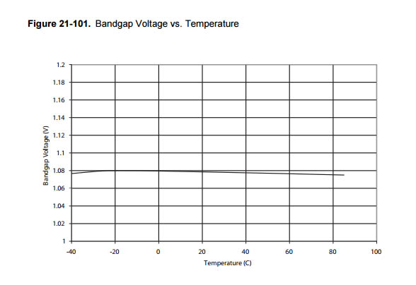
Another useful information is the boundaries within which this processor operates, for example, temperatures and voltages.
In the Week6 I made the Hello World board, but didn't program it. So in order to complete the assignment I tried to program it with something. As seen before, the Hello World has only a button and one LED, so I started with that.
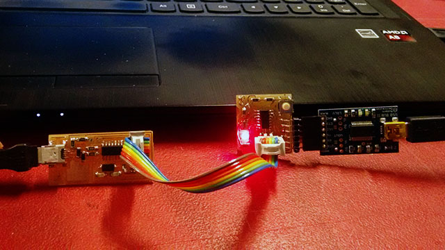
I first downloaded and installed a lot of software that was mentioned in the class, installed the proper drivers for the ISP, the programmer, and the Atmel Studio, just to check out how they works. I also downloaded the Arduino Software, and this was the one that I most liked.
So to program my Hello World board, I first used the examples at arduino software (Arduino IDE). I used the "Blink" example to start. For the Hello World board, as the microcontroller is a ATTINY84, the pin number at the programming is different. For the arduino is the pin 13, but for ATTINY84 and for the board I made was pin 7 at the program, but actually port 6 at the microcontroller.
First I had to configure the Arduino IDE to use my USBTiny and to be able to program a ATTiny84 microcontroller. I followed this tutorial to do it. Then I followed the tutorials for programming but did not succeed. I was having some trouble that I didn't know. I did some search on google with my error, and I found that because I installed Atmel Studio, I can have some troubles using the Arduino Software to program my boards. In fact, it happened, because even using the AVR ISP mk2 was not working.
What I did was to uninstall the Atmel Studio, and reinstalled the USB Tiny and AVR ISP MK2 drivers.
First I tried to program my hello world using my FabISP, but it didnt work. Then I tried using the AVR ISP mk2, and it also didn't work again! I got very frustrated and got stuck again!
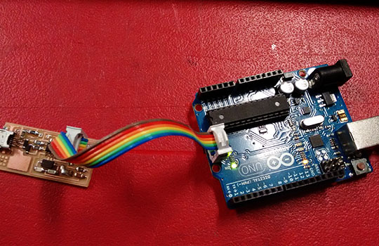
Then Shawn told me to try to program an arduino first, just to check if the programmer was working on my computer, because if they are, it means that the problem should be in my Hello World board.
So using the "Blink" example again, I programmed a Arduino Uno using an AVR ISP mk2 and then it worked well! And then I tried to change the program, changing the delay time between the blinks. Now I used my FabISP to program the arduino. It also worked well!
At this point I knew that my programmers was working properly. So I changed to program my Hello World board again, and it failed again! I checked all my connections and, at first, I thought that everything was ok. Then I found that there was a missing connection to the RESET port at the microcontroller. Instead of making another Hello World board, I fix it making a soldering bridge between the trace and the port.
So I toke off the microcontroller using a hot air gun, made the soldering bridge, and soldered all the microcontroller to the board again. (I updated the process at the Week 6 page). Then I tried to program again on my board, changing again from pin 13 to pin 7 at the arduino software, and it finally worked.
I played a bit with the programming, changing the way that the LED blinks if you press the button. To work with the button you will need to declare some constants and variables, and make the button port as an INPUT. To define the constants and variables, you need to declare them before the "void setup()" and the "void loop()". These are the commands I used to do this:
const int buttonPin = 3; // the number of the pushbutton pin in my board
int buttonState = 0;
Then I used this command to define the button port as a INPUT:
pinMode(buttonPin, INPUT);
To know if the button is being pressed or not, you can use the command "digitalRead" that will "read" the button status:
buttonState = digitalRead(buttonPin);
Then I used the "if" command to change the LED blinking if the button is being pressed.
if (buttonState == HIGH) {
digitalWrite(7, HIGH); // turn the LED on (HIGH is the voltage level)
delay(1500); // wait for a second
digitalWrite(7, LOW); // turn the LED off by making the voltage LOW
delay(1500); // wait for a second
}
if (buttonState == LOW) {
digitalWrite(7, HIGH); // turn the LED on (HIGH is the voltage level)
delay(100); // wait for a second
digitalWrite(7, LOW); // turn the LED off by making the voltage LOW
delay(100);
}